báo cáo hóa học:" Virtual interactive musculoskeletal system (VIMS) in orthopaedic research, education and clinical patient care" pptx
Bạn đang xem bản rút gọn của tài liệu. Xem và tải ngay bản đầy đủ của tài liệu tại đây (2.01 MB, 19 trang )
BioMed Central
Page 1 of 19
(page number not for citation purposes)
Journal of Orthopaedic Surgery and
Research
Open Access
Review
Virtual interactive musculoskeletal system (VIMS) in orthopaedic
research, education and clinical patient care
Edmund YS Chao*
1,5
, Robert S Armiger
2,5
, Hiroaki Yoshida
3,5
, Jonathan Lim
5
and Naoki Haraguchi
4,5
Address:
1
Bjed Consulting, LLC, 9114, Filaree Ct. Corona, CA, 92883, USA,
2
Department of Bioengineering, Johns Hopkins University, Baltimore
MD, 21205, USA,
3
Digital Human Center, National Institute of Advanced Industrial Science and Technology, Water Front, 3F, 2-41-6 Aomi, Koto-
ku, Tokyo, 135-0064, Japan,
4
Department of Orthopaedics, Tokyo Police Hospital, Tokyo, Japan and
5
Orthopaedic Biomechanics Laboratory,
Johns Hopkins University, Baltimore, Maryland, USA
Email: Edmund YS Chao* - ; Robert S Armiger - ; Hiroaki Yoshida - ;
Naoki Haraguchi -
* Corresponding author
Abstract
The ability to combine physiology and engineering analyses with computer sciences has opened the
door to the possibility of creating the "Virtual Human" reality. This paper presents a broad
foundation for a full-featured biomechanical simulator for the human musculoskeletal system
physiology. This simulation technology unites the expertise in biomechanical analysis and graphic
modeling to investigate joint and connective tissue mechanics at the structural level and to visualize
the results in both static and animated forms together with the model. Adaptable anatomical
models including prosthetic implants and fracture fixation devices and a robust computational
infrastructure for static, kinematic, kinetic, and stress analyses under varying boundary and loading
conditions are incorporated on a common platform, the VIMS (Virtual Interactive Musculoskeletal
System). Within this software system, a manageable database containing long bone dimensions,
connective tissue material properties and a library of skeletal joint system functional activities and
loading conditions are also available and they can easily be modified, updated and expanded.
Application software is also available to allow end-users to perform biomechanical analyses
interactively. Examples using these models and the computational algorithms in a virtual laboratory
environment are used to demonstrate the utility of these unique database and simulation
technology. This integrated system, model library and database will impact on orthopaedic
education, basic research, device development and application, and clinical patient care related to
musculoskeletal joint system reconstruction, trauma management, and rehabilitation.
Background
The concept of the "Virtual Human" aims at the under-
standing of human physiology through simulation based
on life-like and anatomically accurate models and data.
On a grand scale, the Virtual Human will lead to an inte-
grated system of human organ structures that explain var-
ious anatomical, physiological and behavioral symptoms
and activities of a "reference human". In recent years, the
explosion of science and technology, creating an overlap
between the biological sciences and the engineering
know-how has made the possibility of Virtual Human as
a reality rather than a visionary concept. This paper intro-
Published: 8 March 2007
Journal of Orthopaedic Surgery and Research 2007, 2:2 doi:10.1186/1749-799X-2-2
Received: 22 December 2006
Accepted: 8 March 2007
This article is available from: />© 2007 Chao et al; licensee BioMed Central Ltd.
This is an Open Access article distributed under the terms of the Creative Commons Attribution License ( />),
which permits unrestricted use, distribution, and reproduction in any medium, provided the original work is properly cited.
Journal of Orthopaedic Surgery and Research 2007, 2:2 />Page 2 of 19
(page number not for citation purposes)
duces the development and applications of a modeling
and computational software package for human muscu-
loskeletal joint system, which will enable the execution of
a wide spectrum of biomechanical analyses under simu-
lated or experimentally measured functional environ-
ment. Therefore, this graphic modeling capability is not
merely aimed for visual attraction. It is an integration of
physiological simulation models coupled with computer
graphics and analysis tools to determine the effects of
physical, ergonomic and environmental conditions on
the human body. This effort represents a trans-discipli-
nary collaboration among bioengineers, computer scien-
tists, and physicians with multiple applications including
medical education, basic research and clinical patient care
– a precursor to the grand challenge of the "Virtual
Human" concept.
This innovative concept and work in progress have long
been overlooked in the field of biomedical research, but it
now represents a major force among a growing number of
investigators in the traditional biomechanics discipline
with the added strength of new engineering technology.
Engineers have been working on adapting and refining
the Virtual Reality (VR) concept for model analysis and
data presentation from 2D, 3D, and even 4D space
through system simulation and graphic visualization. The
well-known flight and vehicular simulators provide realis-
tic environmental and human-factor conditions to train
and monitor physiological responses. However, engineer-
ing aspects of VR differ from those used in the fields of
entertainment and advertising. In addition to visual, tac-
tile, and sensory requirements, bioengineering models
must also satisfy the requirements of being accurate,
quantitative, computational, and interactive. These funda-
mental premises represent the underlying objectives of
the present development and application.
The current simulation technology described as a virtual
interactive musculoskeletal system (VIMS) is a highly ver-
satile simulation tool, providing information in an attrac-
tive, user-friendly and easy-to-understand graphic
environment while allowing the theories and computa-
tional algorithms embedded in the software architecture.
This musculoskeletal biomechanics simulation program
is built on proprietary softwares VisModel™ and VisLab™
(Products of Engineering Animation Inc., Ames, Iowa, a
subsidiary company of EDI, Huston, Texas) and other
commercial utility softwares. It is divided into three
highly integrated components, the "VIMS-Model"; the
"VIMS-Tool" and the "VIMS-Lab" while each of them can
function independently for specific application (Fig. 1). In
order to handle individual variation among the normal
population, homogenous, multi-dimensional and non-
parametric scaling techniques will be required. The origin
of the current concept and the motivation for creating a
graphic-based computational model stemmed from the
early work of biomechanical analyses of musculoskeletal
systems and the technical problems encountered in
model development and in the solution of a special class
of problems [7,8,11,12,24].
Multi-body dynamic analysis of musculoskeletal system
has not received the attention it deserves partially because
of the modeling and analysis difficulties involved. How-
ever, the internal muscle, ligament and joint forces
responsible for producing limb segment external loading
and motion are still largely unknown. The redundancy of
the control variables in the anatomical system and the dis-
tribution of the limb/joint forces among the tendons, lig-
aments, and articulating surfaces were only approximated
using an optimization technique without adequate vali-
dation [15,24,25,27]. Incorporation of graphics with the
model and results visualization has definite advantage but
such an advance has only been attempted recently. While
this proved to be a useful tool in modeling the system and
in interpretation of the results, no comprehensive and in
depth interactive graphics capabilities were available to
execute the analyses when skeletal system is interfaced
with implants or fixation devices. Buford used interactive
three-dimensional line drawings in a kinematic model of
the hand [5]. Later, a more attractive 3D surface model
was introduced to calculate muscle-tendon paths in a bio-
mechanical simulation environment [6]. Interactive
graphical simulation software for modeling of the lower
extremity has been developed [16,17]. The models pre-
sented in this paper utilized rendered and shaded three-
dimensional graphics for display and allows the user to
interactively set muscle paths and joint angles through a
graphical interface.
A user oriented network, the "VIMS-org" (Fig. 1) will be
established on the Internet to encourage close collabora-
tions among different investigators in the musculoskeletal
biomechanics community. This integrated software sys-
tem and model database can impact on the learning of
functional anatomy, the creation of a virtual laboratory
for biomechanical analyses without the use of animals or
cadaver specimens, the development of patient-specific
and device-based models for preoperative planning in
bone fracture management, limb lengthening, skeletal
deformity correction through osteotomy, joint replace-
ment, simulation-based intervention training using vir-
tual instruments and environment, and the establishment
of a visual feedback and biomechanics-based system for
computer-aided orthopaedic surgery (CAOS) and rehabil-
itation.
Journal of Orthopaedic Surgery and Research 2007, 2:2 />Page 3 of 19
(page number not for citation purposes)
Graphic-based model development – "VIMS-
model"
In essence, graphic-based models through simulation can
bring the anatomical data to "life" through biomechanical
analyses, allowing assessment of how the limb segments
meet the functional demands of movement. Initially, ana-
tomic data of the musculoskeletal system must be
acquired and assembled into a model suitable for analysis
and results visualization. Anatomic parameters related to
joint function are quantified, including bone and soft tis-
sue volumes, masses, and their relative orientation to one
another. The ability to modify the anatomy in a model is
necessary during joint function. The database contained
within VIMS-Model includes generic anatomic and
implant/device models, either generated or acquired, and
the necessary data for musculoskeletal simulation with
muscle moment arms, muscle volumes, and ligament rest-
ing lengths. These models and database are stored in suit-
able format that can be accessible for the computational
needs to develop a single fully integrated analysis package.
Geometric and material data acquisition
The Visible Human [36] is a set of volumetric image data
of human anatomy from two cadavers serving as the main
source of the generic models stored on VIMS-Model
library. Boundary seeking algorithm provided by the com-
mercial software, VisModel™ was used to map out the pro-
file of the 3D anatomic components in order to
reconstruct their surface shape volumetrically. CT data
were retrieved and analyzed to build the voxels layer by
layer according to preset gray level threshold to recon-
struct the solid model for long bones containing different
material properties and geometric irregularities. A data-
base on isolated long bones from different populations
combined with structural and material properties will be
used for analysis purpose [10]. Large volume of database
available in the literature and from unpublished reports
will be incorporated later. This data combined with the
available scaling algorithms will provide the capability of
creating individual models adaptable to the generic mod-
els for biomechanical analyses.
The functional flowchart and software structural platform design of the Virtual Interactive Musculoskeletal System (VIMS) and database for biomechanical analysesFigure 1
The functional flowchart and software structural platform design of the Virtual Interactive Musculoskeletal System (VIMS) and
database for biomechanical analyses.
Journal of Orthopaedic Surgery and Research 2007, 2:2 />Page 4 of 19
(page number not for citation purposes)
In soft tissues, the cross-sections of these anatomic struc-
tures are outlined along their lengths, so that the centroi-
dal lines of these tissue structures can be traced in three
dimensions to define their line of action for biomechani-
cal analyses. The muscle's physiological cross-sectional
area [24] is included as an important parameter to deter-
mine muscle stress during static and dynamic activities.
Muscle length and volume data are combined with their
density values reported in the literature to estimate masses
and moments of inertia for limb dynamic analysis. For
cartilage, menisci, labrums, rotator cuff and capsules, the
detailed Virtual Human dataset are used to quantify their
geometry in the models mainly for computational pur-
pose. The articular cartilage thickness is an important
parameter required in the intra-articular contact stress cal-
culation. For the other soft tissue components, their fiber
bundle orientation and insertion site are important for
joint loading analysis. Although these soft tissue parame-
ters are important for biomechanical analyses, no attempt
is made to graphically present them for visualization pur-
pose due to technical difficulties and image size storage
and manipulation limitation.
Models for biomechanical analyses
In addition to musculoskeletal models, VIMS system
library also contains joint replacement implant models
and bone fracture fixation devices for kinematic analysis
and stress/strain evaluation to study their clinical applica-
tion performance through simulation studies. Several
generic models available within VIMS-Model library are
described here to illustrate their utility.
Full skeleton model
A full human skeleton model was adapted from commer-
cial source and modified by EAI (Engineering Animation
Inc., Ames, Iowa) as a general purpose surface model (Fig.
2). Local coordinate systems are imbedded in each skele-
tal component which can be manipulated or animated
under given motion data using EAI's VisModel™ and Vis-
Lab™ software. The surface shape represented by small
polygons is fixed to the local coordinate system to facili-
tate rigid body motion analysis and animation. This sim-
plified model contains several integrated movable
components interconnected by major anatomic joints
with assumed degrees of freedom. No relative motion is
permitted within the spine, trunk, hand, wrist, mid and
hind foot. In spite of this limitation, this global skeletal
model serves the purpose to animate human movement
in normal functional activities and sports actions using
measured or calculated kinematic data for visualization
purpose [29].
Shoulder musculoskeletal model
Detailed musculoskeletal models for the shoulder were
constructed from cadaver specimens using their CT (for
the skeleton components) and MRI (for muscles) data
[18,23]. For other soft tissue details, the cryo-section
images were also used. These are surface models although
they provide the layered muscular, neurovascular (the
brachial plexus), and all underlying skeletal structures in
a composite assembly which are visible three dimension-
ally in a sequential and animated form (Fig. 3A). These
models were used for several kinematic and functional
anatomy studies (Fig. 3B–3D) and they also provided the
basis for muscle joint force analysis and joint contact
stress and ligament tension in activities (Fig. 3E) [28].
Musculoskeletal model of the pelvis and hip
A composite surface model of the pelvis and all muscles
across the hip joint was developed using the whole body
database generated from the Johns Hopkins University,
Biomechanics Laboratory and the Visible Human Dataset
available on the Internet (Fig. 4A). In addition to illustrat-
ing the gross anatomy of the pelvis and the femur, this
model was used to study hip joint contact stress during
activities of daily living [39] (Fig. 4B). By inverting the hip
joint contact stress onto the femoral head, it was also used
to predict the subchondral bone collapse and investigate
femoral head reconstruction due to osteonecrosis (Fig.
4C) [40].
Total hip replacement model
A compounded surface and solid model for the hip joint
was generated from the Visible Human Dataset to simu-
late total hip replacement surgery. A proximal femur/hip
prosthesis model is incorporated to the pelvic model to
study hip range of motion and stress distribution before
and after hip replacement using different implant designs
(Fig. 5) [31]. The hip implant model was developed using
the CAD/CAM files from the manufacturers or taking the
existing implants' plastic replicate for CT scan images.
This compounded model allows both cemented and non-
cemented hip replacement simulations. Joint range of
motion was investigated based on acetabular component
placement, joint surface wear, femoral component neck
design. In addition, surgical approach and prosthesis
placement were also simulated to illustrate the utility of
this model.
Ankle joint contact stress and ligament tension model
Three-dimensional bone models of the talus, calcaneus,
tibia, and fibula based on the Visible Human Dataset
(National Library of Medicine) were scaled to match CT
data recorded from cadaver specimens in different joint
angles at 10° increments from 30° of dorsiflexion to 50°
of plantar flexion covering the entire range of ankle
motion during level walking (Fig. 6) [41]. Regions of
potential bony contact were identified by the contour
lines of the subchondral bone on each slice of the orthog-
onal CT sections and were then stacked to create joint con-
Journal of Orthopaedic Surgery and Research 2007, 2:2 />Page 5 of 19
(page number not for citation purposes)
tact surfaces. Rows of tensile strings for the ligaments and
the interosseous membrane were inserted at the anatomi-
cal regions identified from the dissection data of the same
specimen. This model was used to study ankle joint con-
tact stress and ligament tension and to predict the location
and treatment options of malleolar fracture [42]. This is
the first time that the ankle normal contact and ligament
stresses have been quantified using biomechanical analy-
sis and simulation.
External fixator – bone fracture reduction, lengthening and
osteotomy model
Three types of unilateral external fixators were modeled as
solid rigid bodies of adjustable links interconnected by
different joints (Fig. 7A). Any long bone or pelvis can be
incorporated with the fixator forming an open or closed
linkage system to study fracture reduction, bone lengthen-
ing and osteotomy adjustment through callus distraction
planning using the kinematic chain theory [26]. In addi-
tion to fixator adjustibility studies, this model is now
being extended to investigate fixator stiffness performance
for device evaluation and design optimization. Finally, an
EBI DFS Dimension Fixator™ was modeled graphically
using the CAD/CAM software to demonstrate fracture
reduction through fixator joint adjustment for both bridg-
ing and non-bridging applications (Fig. 7B). The parame-
ters of a distal radius deformity were defined from the CT
scans and the anterior-posterior and lateral radiographs at
the fracture site. Alignment based on the bony landmarks
of the radius relative to the intact contralateral side
defined the deformity according to dorsal/volar transla-
tion, radial shortening and radial/ulnar translation.
Radial and volar/dorsal tilts and axial rotation along the
long axis of the radius described the displacement and
angulation of the distal radial fragment. Because the fixa-
tor is functioning in the similar manner as a complex
robotic arm, the bone-fixator system could be modeled as
a multi-link closed kinematic chain [43].
There are other models stored in the VIMS "Model
Library" for visualization and biomechanical analysis.
Separate graphic and animation files are also archives for
demonstration purpose. New models and modifications
of the existing ones can be added to the library which will
be updated periodically. This database is designed and
managed as a "shared" resource among the VIMS users
within the network described as the "VIMS.org".
Geometric scaling of models
Nearly all models in the VIMS database are generic in
nature and they were developed from the same Visible
Human Dataset or the Johns Hopkins Virtual Human
database. It would be impractical to utilize the same labo-
rious process to derive an individual model for a specific
person or patient for visualization and analysis purpose.
To depict a patient's skeletal deformity and to perform
The three dimensional full-skeleton model of the human used for automobile impact study (left), gait analysis after hip replace-ment (middle), and the composite view of the full human skeleton to replicate baseball pitching dynamics (right)Figure 2
The three dimensional full-skeleton model of the human used for automobile impact study (left), gait analysis after hip replace-
ment (middle), and the composite view of the full human skeleton to replicate baseball pitching dynamics (right). The calculated
shoulder and elbow joint forces (yellow single arrow) and moments (blue double arrow) are shown together with the ground
reaction force (yellow arrow) measured by a dynamic force plate for the entire cycle of pitching.
Journal of Orthopaedic Surgery and Research 2007, 2:2 />Page 6 of 19
(page number not for citation purposes)
his/her pathomechanical analysis, the specific bone and
joint geometry and dimension can be derived from the
generic model using the acquired x-ray or CT data in order
to evaluate the biomechanical effects of the pathology and
to simulate the anticipated treatment outcome based on
various clinical scenarios. This method has been described
as the "parametric scaling" technique in the simulation
environment using custom software or commercial pro-
gram such as Pro/ENGINEER™ (PTC Engineering Solu-
tions, Parametric Technology, MA). For joint implants,
spine and fracture fixation devices, scaling can be accom-
plished using different CAD/CAM programs. Data for
each cross section of the bone can be associated with the
plane or its boundary which is expressed in mathematical
forms (Fig. 8). Splines used to define the cross-section
boundary in each plane are modified point by point. For
bone and soft tissue in the musculoskeletal system, this
process is extremely difficult due to the complexity of the
geometry involved.
The feature-based solid modeling technique was used in
the past since the best parameters and anatomic land-
marks for human appendicular and axial skeleton are
largely unknown. To identify the most important param-
(A). A composite muscular, neurovascular and skeletal model of the shoulder visualized in a sequential manner from the super-ficial muscles to the underlying bony structure for anatomical studiesFigure 3
(A). A composite muscular, neurovascular and skeletal model of the shoulder visualized in a sequential manner from the super-
ficial muscles to the underlying bony structure for anatomical studies. (B). The sequential images of a cadaver shoulder during
passive elevation of the humerus in the plane of the scapula. These shoulder models were created from CT data of cadaver
specimens. The kinematic data, measured by using electromagnetic "sensors" (Flock of Birds™, Ascension Technology, Col-
chester, VT) fixed to the humerus, scapula and clavicle and a "source" mounted on the trunk of the cadaver, was used to quan-
tify the shoulder motion rhythm of all the bony structures involved. (C). A solid model of a cadaver shoulder highlighting the
history of the closest points between the greater tuberosity and the acromioclavicular ligament during the Hawkins maneuver
for impingement test. (D). The same model used to study thoracic outlet syndrome under provocative maneuver tests. The
thoracic outlet area between the clavicle and the surface of the 1
st
and 2
nd
ribs (marked by the mesh structure) is quantified and
highlighted in red color. (E). The glenoid surface model for joint contact area/stress and ligament-capsule tensile stresses study
during arm elevation.
Journal of Orthopaedic Surgery and Research 2007, 2:2 />Page 7 of 19
(page number not for citation purposes)
eters and quantify the range of values based on as many
bones as possible should be pursued by selecting specific
scaling algorithms taking the individual's age, gender,
development, aesthetic and ethnic background into
account. However, the VIMS-Model is intended to build a
host of musculoskeletal joint generic models that can be
manipulated to perform realistic biomechanical analyses
on a general population or on individual patient with spe-
cific pathologic conditions. The problems associated with
soft tissue scaling and graphic presentation during move-
ment are extremely difficult to solve but they should not
affect the outcome of the intended biomechanical analy-
sis on the models subject to the known loading and
motion conditions. When the precise 3D geometry of the
patient's musculoskeletal anatomy and pathology is
required, his/her CT and MRI data could be utilized to
reconstruct the individual model with the added time and
cost.
In skeletal scaling, the model must be constructed in a
way that incorporates appropriate physical assumptions
and mathematical approximations appropriate only for
the biomechanical analyses to be performed. For struc-
tural models, computer-aided design (CAD) feature based
solid modeling tools are the state of the art. While the
voxel-based models with material texture or morphology
incorporated are desirable, the surface models [2,33,37]
are the standards for medical applications. Solid models
(A). The surface model of the pelvis and the proximal femur with the key muscles across the joint used for the dynamic force analysis of the hipFigure 4
(A). The surface model of the pelvis and the proximal femur with the key muscles across the joint used for the dynamic force
analysis of the hip. (B). The model used to study acetabulum contact area and stress distribution during activities of daily living
involving the hip. The hip joint reaction force (arrow) and contact stress distribution at three positions during the gait cycle for
the left (highlighted) leg calculated using the discrete element analysis (DEA) technique. The blue areas indicate the regions of
the lowest stress while the yellow and green regions indicate the locations of higher stresses. (C). The proximal femur model
used to investigate subchondral bone collapse due to osteonecrosis (OS) and femoral head reconstruction.
Journal of Orthopaedic Surgery and Research 2007, 2:2 />Page 8 of 19
(page number not for citation purposes)
to fit the FEM codes for stress analysis can be scaled para-
metrically which allow the geometry of a bone to be mod-
ified to match specific entry data. In this case, the
visualization of the analysis results will be presented on
more refined graphic models to enhance the appeal of
complex data to both physicians and engineers.
"VIMS-tool" for biomechanical analyses
Kinematic analysis
In musculoskeletal systems, limb and joint motion is
important to define normal functional requirements and
the possible pathologic effects caused by joint diseases or
neuromuscular abnormalities. Although such informa-
tion could be observed or measured on living persons, no
information could be derived to study the underlying
skeletal movement under direct visualization. Basically,
there are two types of motion, the global limb and joint
motion and the local articulating surface displacement.
The global motion can be quantified with fair accuracy
using any of the motion analysis systems or externally
mounted linkage systems. However, joint articulating sur-
face motion is extremely difficult to measure and visual-
ize. Therefore, the modeling and analysis capability in
VIMS will be limited to global joint motion.
Joint rotations in three dimensions are expressed in terms
of the familiar Eulerian Angles to facilitate musculoskele-
tal dynamic analyses and for movement animation. There
are two most frequently used systems for Eulerian Angle
definition, the "3-axes" system and the "2-axes" system.
The use of the latter system is usually for the purpose of
avoiding the ambiguity of rotational reference when two
axes become co-liner, the "gimbal lock" phenomenon,
under large range of joint motion such as in the shoulder.
In two connecting skeletal segments, their relative motion
from one position to another can be determined if their
localized coordinate axes are defined in reference to an
inertial reference frame.
Finite rotation of a limb segment is sequence dependent.
However, the well-known "gyroscopic" system can be
used to describe the unique Eulerian angles which will be
rotational sequence independent as applied to the use of
external linkage measuring device for joint motion
The total hip replacement model including the bone and prosthesis components used to study the effects of femoral neck design and implant placement on joint range of motion and potential dislocationFigure 5
The total hip replacement model including the bone and prosthesis components used to study the effects of femoral neck
design and implant placement on joint range of motion and potential dislocation.
Journal of Orthopaedic Surgery and Research 2007, 2:2 />Page 9 of 19
(page number not for citation purposes)
[9,11,22]. This coordinate system was renamed as the
"anatomic" axes for the knee joint [20]. It is important to
note that such joint motion reference system cannot over-
come the "Gimbal Lock" problem (when two of the joint
rotational axes are co-linear) and since they are non-
orthogonal, transformation to an orthogonal system is
required for dynamic analysis.
Bone alignment correction under external fixation can be
studied using rigid body kinematic analysis. When bone
segments involved in fracture, osteotomy or lengthening
The human ankle joint model of the distal tibia, fibula, talus and calcaneus plus all the surrounding ligament connecting these bony elementsFigure 6
The human ankle joint model of the distal tibia, fibula, talus and calcaneus plus all the surrounding ligament connecting these
bony elements.
Journal of Orthopaedic Surgery and Research 2007, 2:2 />Page 10 of 19
(page number not for citation purposes)
cases are immobilized by an external fixator, the entire
system can be modeled as a spatial linkage chain and
studied using the movability analysis using the homoge-
nous 4 × 4 transformation matrix [11]. Such analysis can
aid to device performance evaluation, design modifica-
tion, and pre-treatment planning. The skeletal-fixator sys-
tem can also be regarded as a structure to study its stability
behavior especially the micro-motion occurred at the
bone fracture or lengthening site. The external fixator
adjustibility and stiffness analyses algorithms are availa-
ble in the VIMS-Tool package for specific applications in
different anatomic regions. When bone lengthening or
joint motion is required under external fixation, the fixa-
tor can be regarded as a robotic device to provide the ideal
lengthening regime and skeletal joint motion by adjusting
the components of the fixator in a predetermined fashion.
This analysis program will greatly advance the technology
of external fixation in orthopaedics and traumatology.
Joint reaction forces and moments determination
A technique for quantifying the joint reaction forces and
moments has been widely applied to all major joints. The
algorithm for calculating the reaction forces and moments
acting at these joints are based on skeletal models with
inter-connecting rigid links. The mass, center of mass, and
moment of inertia for the anatomic segments will be esti-
mated or retrieved from the database in VIMS-Model. The
velocity and acceleration of each link will be numerically
derived from measured displacement. The joint reaction
force and moment will be quantified using the Inverse
Dynamics Analysis approach contained in the VIMS-Tool
package [8,13,14].
Distribution of muscle forces and joint constraints
The muscles acting about a joint will be modeled as force
vectors applied along the muscle centroidal lines through-
out the kinematic motion range. In VIMS-Model, the key
(A). The sequential exposures of the EBI Dynafix™ external fixator/tibia model illustrating the malalignment correction path by adjusting the fixator joints simultaneously in small incrementsFigure 7
(A). The sequential exposures of the EBI Dynafix™ external fixator/tibia model illustrating the malalignment correction path by
adjusting the fixator joints simultaneously in small increments. (B). The EBI DSF Dimension™ wrist fixator used to immobilize
the hand relative to the forearm which could be used under the bridging type (with proximal pins in the diaphysis of the radius
and distal pins in the metacarpal plus additional intermediate pin to fix the distal radial fracture fragment) and the non-bridging
type (without the intermediate pin fixing the distal radial bone fragment) applications.
Journal of Orthopaedic Surgery and Research 2007, 2:2 />Page 11 of 19
(page number not for citation purposes)
muscles and their properties related to each joint function
are documented to facilitate the dynamic analysis formu-
lation. These muscle forces are required to balance the
external forces and inertial forces acting about each joint.
Quantifying the individual muscle forces is an indetermi-
nate problem, since there are more unknowns than equa-
tions. Therefore, optimization techniques will be
combined with the equations of motion to solve for the
muscle forces. The underlying assumption behind the
optimization method is that the central nervous system
controls muscle action by minimizing some performance
criteria or cost function [1,15,25,38]. The system of equa-
tions will also be subjected to the constraint that the mus-
cle stresses, expressed as the muscle force divided by the
physiological cross-sectional area, are non-negative and
bonded. Several optimization criteria are incorporated in
the VIMS-Tool software and they can be refined and mod-
ified according to more up-to-date development or based
on investigators' own choices.
Intra-articular contact stress and ligament tension
The joint constraint force can be further decomposed into
joint contact stresses and ligament tension using the dis-
crete element analysis (DEA) technique [19]. This analysis
technique can be modified to accommodate the mis-
match in joint geometric shape and to incorporate addi-
tional soft tissues such as menisci, labrums, rotator cuff
and the joint capsule. In this analysis, bones are treated as
rigid bodies while the articular cartilage and the ligaments
are modeled as matrices of compressive or tensile springs
[21,35]. Furthermore, to satisfy the theoretical require-
ments of such analysis, the system must be kept in static
or quasi-static equilibrium and thus allowing only infini-
tesimal (or virtual) displacement only in translation. The
discrete element analysis (DEA) method requires less
computational time than finite element analysis (FEA)
techniques and it has been shown to provide equivalent
results in estimating joint contact or implant/bone inter-
face stresses [34].
Joint contact area will be determined between the two
bone surfaces at each functional position. This contact
area will be midway between the two bones separated by
the cartilage. A compressive spring is placed on the cen-
troid of each polygon on the concave side of the joint ori-
ented normal to the polygon surface. Any spring that does
not intercept the opposing bony surface of the joint will
be eliminated from the contact area. Therefore, the joint
contact area represents a subset of the joint articulating
surfaces between the two bones. Ligament resting length
and location are determined from the anatomic database.
A series of parallel tensile springs will be used to model
the ligaments or joint capsule to predict their tensile
stresses in each joint position. Using the principle of min-
imum potential energy, the equilibrium equations
describing the spring deformation are derived by applying
Castigliano's theorem and the indeterminate problem can
be solved using a Gauss-Jordan elimination process. The
entire computational algorithm is iterative in nature since
each step of joint loading under the equilibrium condi-
tion, the joint compressive springs carrying tensile load
(spring length increased from its resting length before
loading) or the tensile springs carrying compressive load
(spring length decreased from its resting length before
loading) must be removed from the system and the equi-
librium analysis repeated based on the new area of joint
contact and ligament cross-section. An appropriate con-
Comparison of the generic femur model and a patient-spe-cific femur with shorter statue and a mild bowing deformity derived from the generic model using parametric scaling techniqueFigure 8
Comparison of the generic femur model and a patient-spe-
cific femur with shorter statue and a mild bowing deformity
derived from the generic model using parametric scaling
technique.
Journal of Orthopaedic Surgery and Research 2007, 2:2 />Page 12 of 19
(page number not for citation purposes)
vergence criterion will be adapted using the least-square
minimization principle for the iterative process.
Bone and implant stress analysis
Using established 3D finite element (FE) models acquired
or developed, the stress and strain in the bone, ligament,
implant and their interfaces can be determined using any
commercial FEM codes. Special software, such as
ABAQUS™ (Hibbit, Karlsson & Sorensen, Inc., Pawtucket,
RI) or PATRAN™ (MacNeal-Schwiendler Corp., Los Ange-
les, CA) finite element code can be imported to the VIMS-
Model platform to create new FE mesh using existing CT
data. The size and shape of prosthesis models can be
changed using the Pro/ENGINEER™ software to fit the
host bone model. Interface and boundary conditions are
handled by using the special element types available in
the commercial codes or to be developed and incorpo-
rated to VIMS-Tool for special application. Effective post-
processing software are imported and combined with the
model to provide graphic presentation of the results
under loading and physical activities.
Biomechanical analyses in virtual environment –
"VIMS-lab"
The applications of VIMS simulation technology to date
have been limited by the availability of models and the
ability to incorporate soft tissue structures in the system
analysis. However, several examples are presented here to
demonstrate the unlimited potential of the current tech-
nology in creating virtual laboratory environment for bio-
mechanical analyses not possible in the past. These also
help to demonstrate that the current technology is not and
should not be regarded as merely a graphic-based tool for
visualization purpose alone.
Graphic animation of musculoskeletal kinematics
Graphical animation has been combined with computa-
tional analysis to animate musculoskeletal kinematics
and to quantify relevant parameters related to function
anatomy. Shoulder motion rhythm was investigated dur-
ing passive humerus elevation (Fig. 3B) [18] and in the
provocative maneuver tests used to examine shoulder
impingement and the thoracic outlet syndrome (Fig. 3D)
[23]. To record the kinematic data, electromagnetic sen-
sors were used to track the motions of the humerus, scap-
ula and clavicle in three-dimensions as the shoulders were
passively manipulated. Each humerus was elevated in for-
ward flexion, in abduction in the coronal plane, and in
abduction in the scapula plane. Three provocative maneu-
vers used to test for shoulder impingement. To quantify
the 3D motions, anatomic coordinate systems were cre-
ated for the humerus, scapula, clavicle and the trunk. Geo-
metric shapes were mapped to the graphically
reconstructed bone anatomy using the iterative closest
point algorithm to consistently orient the anatomic coor-
dinate systems for each specimen [4]. The results in these
studies helped to demonstrate the special utility of graph-
ical animation to define joint coordinate systems and
enhancing the interpretation of finite joint rotation
results. Complex anatomical changes during skeletal
movement can now be studied quantitatively under direct
visualization.
Kinematic and muscle force analysis of the shoulder
The joint reaction forces within the shoulder have been
quantified for baseball pitching. The kinematic data of
collegiate pitchers was collected in a motion analysis lab-
oratory equipped with a 7-camera, 500 Hz UV-light based
motion capture system (Qualisys™, Gothenburg, Swe-
den). Reflective markers were taped to the skin of each
pitcher at the wrist, elbow, shoulder, hip, knee and ankle.
A marker was also fixed to the baseball. The marker posi-
tions were digitized throughout the pitching motion and
recreated on the generic full-skeleton model to animate of
the pitching motion. The upper arm and forearm free-
body diagram was taken at the shoulder joint for force
analysis. The linear and angular accelerations of each rigid
body were determined from the kinematic data. The accel-
eration data and the mass data from each link were used
to quantify the joint reaction force and moment at the
shoulder [28,29] (Fig. 2). This model is being extended
for muscle and joint constraint force analysis while these
forces were used to determine glenoid contact area and
stress distribution during straight arm elevation in differ-
ent planes (Fig. 3E).
Hip joint pressure distribution during gait
The surface model of a pelvis and the matching left femur
from the CT scan images of a male cadaver (Visible
Human, National Library of Medicine) stored in VIMS-
Model was used to characterize the acetabular pressure
distribution during gait and in activities of daily living
(Fig. 4B). The contact area of the acetabulum was deter-
mined based on the orientation of the normal vectors for
each polygon on the acetabular surface mesh. The discrete
element analysis (DEA) technique available in VIMS-Tool
was applied to determine the contact stress distribution
on the acetabulum surface under loading [19]. The con-
tact force acting on the pelvis from the femur during gait
[3] was normalized and applied to the model at five per-
cent intervals in the stance phase of gait. The force data
was transformed from the femur coordinate system to the
acetabular coordinate system based on the averaged joint
rotation data for normal subjects walking on a treadmill.
The pelvic and femoral coordinate systems used experi-
mentally were reproduced on the graphic model to trans-
fer the hip joint force vector to the joint contact model.
Computer analysis of the hip joint included two stages. At
the first stage, the shapes of the femoral head and the
Journal of Orthopaedic Surgery and Research 2007, 2:2 />Page 13 of 19
(page number not for citation purposes)
acetabulum were created from the Visible Human dataset
[1] and the potential contact area for an individual was
established from his/her anteroposterior radiograph data
[2]. The cartilage between the acetabulum and the femoral
head was represented by 4000 'equivalent' unilateral
springs. In order to find the joint pressure distribution the
acetabulum and the femoral head were assumed to be
rigid bodies. The loads at the joint were chosen as the hip
contact forces during ADL [3]. The pressure distribution
was obtained by using the discrete element analysis
(DEA). At the second stage, the hip pressure obtained
from the DEA was inverted to a distributed load on the
femoral head for the subsequent finite element (FE) anal-
ysis.
The spatial finite element model used continuum brick
elements for the cancellous bone and thin shell elements
for the cortical bone. The nodal points of the contacting
brick and shell elements were properly adjusted. The fem-
oral head was rigidly fixed at the plane separating it from
the femoral neck. The necrotic area was considered as a
cone with the base angle of 2p/3 radian. ABAQUS™ soft-
ware (Hibbit, Karlsson & Sorensen, Inc., Pawtucket, RI)
was utilized for the eigenvalue buckling (instability) anal-
ysis of the cortical shell under the normal and necrotic
conditions.
Two Eigenvalue buckling analyses were performed under
the AVN conditions of degrading elastic properties of the
femoral head [40]. First, the Young modulus of the corti-
cal shell was chosen to be equal 1.0 GPa and the critical
pressure was computed for the varying Young modulus of
the cancellous bone: the left diagram. Second, the Young
modulus of the cancellous bone was chosen to be equal
1.0 MPa and the critical pressure was computed for the
varying Young modulus of the cortical shell: the right dia-
gram which may lead to femoral head collapse (Fig. 4C).
When the normal femoral head was considered where the
Young modulus was chosen to be equal 10.0 GPa and 1.0
GPa for the cortical and cancellous bone accordingly, neg-
ative critical pressure was obtained reflecting the strong
compressive strength to sustain any of the normal loading
applying to the hip.
Ankle joint contact stress and ligament tension during
stance phase of gait
Joint articular contact and ligament loading were explored
using the DEA technique by establishing a region of elastic
elements between rigid bodies representing bones. Articu-
lar cartilage was represented by compressive springs and
ligamentous tissue was modeled using tensile springs.
Three-dimensional bone models of the talus, calcaneus,
tibia, and fibula based on the Visible Human Dataset
(National Library of Medicine) were scaled to match CT
data recorded principally for this study of a cadaver in dif-
ferent flexion angles at 10° increments from 30° of dorsi-
flexion to 50° of plantar flexion which covered the entire
range of ankle motion during level walking. Regions of
potential bony contact were identified by the contour
lines of the subchondral bone on each slice of the orthog-
onal CT sections and were then stacked to create a contact
surface. The contact surfaces were subdivided into approx-
imately 10,000 triangular mesh elements to place the uni-
directional compressive springs. Rows of tensile springs
for the ligaments and the interosseous membrane were
inserted at anatomical positions as identified from dissec-
tion data of the same specimen. The stiffness of the
springs was determined from previous data.
We applied physiological loads approximating that dur-
ing normal walking based on previously published data
[1] for an 80 kg subject. Constraint forces through the
ankle joint were used to calculate the deformation of the
spring element system once an equilibrium state was
achieved. The model was evaluated at discrete frames dur-
ing the stance phase of gait to study the relationship
between ankle position and joint loading on the contact
mechanics characteristics and the loading of individual
ligaments (Fig. 6) [41].
Contact characteristics and ligament tensions associated
with the normal ankle joint during the walking cycle are
shown (Fig. 9). As anticipated, the major ankle joint load-
ing during the stance phase is through the articular surface
of the joint. However, the posterior tibiofibular ligament
(especially the inferior branch) was loaded during the
heel strike and toe off periods of the stance phase. Loading
of the medial malleolus was observed only near the mid-
stance to heel off frames when dorsiflexion was involved.
The tibio-talar articulation showed full congruency
through the majority of the stance phase with peak pres-
sure developing anteriorly towards the toe-off frame. As
the flexion angle of the ankle joint changed from dorsi-
flexion to plantar flexion, the posterior malleolar contact
pressure increased (Fig. 10). Hence, when patients with
malleolar fractures and treated with cast or brace immobi-
lization, thew ankle should be placed in dorsiflexion [42].
Kinamic simulation of external fixator adjustment for
bone fracture reduction
In the management of bone fracture using an external fix-
ator, adjustment of the bone segment is often necessary to
reduce the residual deformities. For a unilateral external
fixator, the ability to adjust rotational and translational
deformities is limited. Furthermore, if favorable local bio-
mechanical conditions can be reliably and conveniently
implemented and maintained using an external fixator,
fracture or osteotomy union can be greatly enhanced. The
Dynafix
®
(EBI, Parsippany, New Jersey) unilateral external
fixator is composed of four pins inserted into the proxi-
Journal of Orthopaedic Surgery and Research 2007, 2:2 />Page 14 of 19
(page number not for citation purposes)
mal and distal bone segments, two telescoping pin
clamps, a central rotary joint, and four sets of revolute
joints. A transverse fracture was simulated at the midshaft
of the tibia and the bone segments were modeled as rigid
bodies. The malalignment of the proximal segment with
respect to the distal fragment, expressed by the transfor-
mation matrix, was determined radiographically using
anatomical landmarks. For a 30° rotational malalign-
ment and a 6-mm fracture gap, correcting the deformity
required large rotations at the two inner revolute joints
and the rotary joint [26] (Fig. 7A). Based on the same
adjustment solution, different correction sequences gen-
erated different reduction paths, some of which produced
bone end collisions or excessive soft tissue stretching. A
simultaneous adjustment of all the joints in small incre-
ments was found to be the optimal reduction with mini-
mal soft tissue interruption and no bony interference. This
is a typical example of using VIMS technology for practical
and relevant clinical application based on biomechanical
analysis results.
Another example is shown to illustrate the reduction of a
distal radial fracture and the corresponding fixator joint
adjustments required. The same optimization process
went through an average of 34 iterations to arrive within
1.e-7 of the objective function for the final solution
parameters. The convergence rate averaged 3 seconds on a
modern personal computer using the neutral fixator con-
figuration as the initial solution estimate. Upper and
lower bounds imposed on the revolute joints improved
the solution convergence and avoided redundant solu-
tions due to the periodicity of the trigonometric func-
tions. For each treatment sequence for the same wrist
fracture and fragment displacement, the bone correction
path was calculated from the relative 3D coordinates of
the fracture ends. Adjustments performed upon the joints
individually resulted in the largest (32.1 mm) deflections
of the distal fragment off the long axis in the axial plane
whereas the incremental reduction had a maximum devi-
ation of 4.89 mm. The axial plane deviation was calcu-
lated as the magnitude of the x and z coordinate
differences of the distal fragment relative to the proximal
fragment (Fig. 7B).
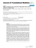
Ankle contact stress distribution and ligament tension in the tibiotalar and talofibular joints during the stance phase of gaitFigure 9
Ankle contact stress distribution and ligament tension in the tibiotalar and talofibular joints during the stance phase of gait. (A)
early stance, ankle in plantar-flexed position, (B) mid-stance, ankle in neutral position, (C) late stance, ankle in dorsi-flexed
position.
Journal of Orthopaedic Surgery and Research 2007, 2:2 />Page 15 of 19
(page number not for citation purposes)
Range of motion after total hip replacement
Stem-on-cup and femur-on-pelvis impingement limit the
hip range of motion after total hip replacement. A compu-
ter graphic model was used to quantify the range of
motion for an intact femur and after total hip arthroplasty
[31] (Fig. 5). The influence of cup orientation and acetab-
ular wear on the range of motion was quantified. The
maximum flexion was similar for the intact femur and the
implanted stem with the cup at 45° abduction and 10°
anteversion. The maximum flexion increased as the cup
Contact pressure distribution at the tibial platfond loaded in ankle dorsi-flexed positionFigure 10
Contact pressure distribution at the tibial platfond loaded in ankle dorsi-flexed position.
Journal of Orthopaedic Surgery and Research 2007, 2:2 />Page 16 of 19
(page number not for citation purposes)
was abducted and anteverted. The maximum extension
was greater for the implanted stem than the intact femur
for all cup orientations, with the exception of a small
range with the femur externally rotated. The maximum
abduction for the intact femur was greater than or equal
to the maximum abduction for the implanted stem with
the cup at 45° abduction and 10° anteversion and the hip
rotated internally. Impingement occurred between the
prosthesis neck and acetabular rim when the femur was
externally rotated, but occurred between the greater tro-
chanter and pelvis for internal rotation. The maximum
abduction increased as the cup was abducted. Stem
implantation had little influence on the maximum adduc-
tion because of impingement between the lesser tro-
chanter and the pelvis. A typical superior wear pattern
decreased the maximum flexion, extension, and abduc-
tion by 9° or more with the femur at 0° internal rotation.
Model validation and scope of application
Sufficient validation of the virtual models used in VIMS
technology is essential to establish its needed credibility.
The Dynamic Knee Simulator (Fig. 11) developed by the
author in closed collaboration with MTS (MTS System
Corporation, Eden Prairie, MN) will be used to validate
the model and analysis algorithms related to the knee
joint [30]. On this simulator, the knee specimen is instru-
mented to measure a simulated squatting activity under
gravitational load of the body. The measured joint contact
pressure and the bone internal force and moment will be
compared to that calculated using the VIMS-Tool compu-
tational algorithms and the generic knee model available
in the VIMS-Model library after appropriate scaling. Abso-
lute validation of the virtual model would be difficult but
unnecessary as long as the trend of the predicted result
match that measured on the Simulator under an identical
loading regime. Additional test setup involving other joint
models and analysis conditions will be developed to pro-
vide an overall qualitative assessment of VIMS-Model,
VIMS-Tool, and VIMS-Lab.
Discussion and summary
The "Virtual Human" is an exciting reality for biomechan-
ical analyses and simulation well demonstrated in this
paper using the musculoskeltal system as the example.
With further development, this technology shall become
a broad foundation with full-featured analysis capability,
robust model library and database, and a well-organized
laboratory environment to serve as a biomechanical sim-
ulator for a wide spectrum of basic science and clinical
applications. This simulation technology unites the exper-
tise in biomechanical analysis and graphic modeling to
investigate joint and connective tissue mechanics and to
visualize the results in both static and animated forms
together with the system involved. Adaptable anatomical
models including implants and fracture fixation devices
and a computational infrastructure for static, kinematic,
inverse and forward dynamic, joint contact pressure, stress
and strain analyses under varying boundary and loading
conditions are incorporated on a common software plat-
form is certainly a timely and significant advance in the
field of musculoskeletal biomechanics to provide the
needed impetus to revive its interest and emphasis.
This simulation technology will in no way to completely
replace the need to conduct experimental testing using
human and animal anatomical specimens mounted on
universal testing machines or custom-made joint simula-
tors. Although time-related simulation on material fatigue
failure or tissue growth and remodeling, animal study is
still the main stack in bone and joint research and implant
development. The results generated from all of these
experimental studies, experimental or theoretical, will rely
on controlled clinical trials to prove their relevance and
efficacy. What the VIMS can offer is a generic database for
comparative purpose for normal and patient population
studies. In individual patient, it also provides the unprec-
edented capability to assist physician and surgeon to opti-
mize treatment protocol to improve clinical outcome and
minimize risk.
This simulation software and database were developed for
the purpose of enhancing research, education, and clinical
patient care related to musculoskeletal joint function at
the structure, organ, and system levels. No effort is made
to model and analyze connective tissue at the material
level. Therefore, VIMS at its current development is lim-
ited to structural analyses of the musculoskeletal system
to provide the front-end data which could be used later for
the down-stream tissue level modeling and analysis pur-
pose. It would be desirable, however, that the analysis
tools for muscle force determination could include some
neuromuscular control theory so that future simulation of
musculoskeletal system can be expended to include syn-
thesis problem related to its physiological performance.
From the clinical point of view, this technology should
have strong appeal to both patient care and rehabilitation
training using its unique graphic-based models and com-
puter animation of their biomechanical responses to
loading and motion under normal and pathological con-
ditions.
Several computational algorithms and model library data-
base have been integrated into the VIMS software plat-
form on a SGi super computer main frame under the Unix
operating system. All of the independent analysis compo-
nents of the software are accessible through a single
graphical user interface (GUI). This software package
could be modified to fit the X-Windows/OpenGL envi-
ronment in the future. The users will get the access to the
VIMS database and search through the model library to
Journal of Orthopaedic Surgery and Research 2007, 2:2 />Page 17 of 19
(page number not for citation purposes)
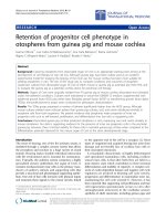
The Dynamic Knee Simulator used to study knee flexion and joint loading under simulated squatting activityFigure 11
The Dynamic Knee Simulator used to study knee flexion and joint loading under simulated squatting activity. Independent loads
are applied to the simulated hip joint, the medial and lateral hamstrings tendons and the quadriceps tendon using hydraulic
actuators. The tendons are secured to the loading actuators using cryo-clamps. The MTS Model 790.00 TestStar™ II Control
System software (MTS Systems Corporation, Eden Prairie, MN) was used to control and monitor all motion and loading condi-
tions.
Journal of Orthopaedic Surgery and Research 2007, 2:2 />Page 18 of 19
(page number not for citation purposes)
select the desirable musculoskletal region and the ortho-
paedic implant or device for the intended simulation and
analysis. The kinematic data of the anatomic system
involved in functions of daily living or sports activities
could be adapted from the literature or measured to serve
as the input data for biomechanical analysis on the
generic models. The analysis results will be graphically
presented and animated using the VisLab™ software (EAI,
Ames, Iowa). Unfortunately, this utility software plus the
VisModel™ package are no longer being served by the
commercial firm and they need to be converted to a PC-
based operating system in order for the VIMS to gain
acceptance and popularity in the public domain.
The VIMS system was developed with the intention of
being shared among a small group of devoted users. The
current version of VIMS system is distributed among nine
institutions worldwide to form the basic members of a
users' organization. To assure uninhibited and unlimited
utilization of the original form of the VIMS software and
its analysis concept, all users are obliged to follow a set of
guiding principles: 1) To follow the "Copyleft" restric-
tions; 2) To share the new developments in model refine-
ments and computational algorithms; 3) To provide free
consultations and trouble-shooting services among all
users; and 4) To provide an "Open Door" policy to
encourage surgeons and bioengineers to utilize VIMS for
basic research and clinical application. A users' group, the
"VIMS.org", will be organized to facilitate software and
model library upgrading. Ultimately, Internet access
option to the software should be established but to main-
tain the necessary security and assure a user-friendly envi-
ronment would be the critical challenge. To maintain the
vitality of this technology and continue to serve the gen-
eral users in the field, limited patents and copyrights will
be necessary to provide specific software systems in differ-
ent anatomic regions for special orthopaedic applications
using the Windows operating system will broaden the
utility of this powerful simulation tool to revive the
importance of biomechanics in musculoskeletal system
reconstruction and rehabilitation.
This integrated system will no doubt making the learning
of functional anatomy easier and creating the virtual lab-
oratories on the Internet to share the resources, analysis
algorithms and research findings. Such capability will
expand the scope and utility of musculoskeletal biome-
chanics without relying upon the use of animals or
cadaver specimens while restricted by the limitation of
models and loading complexity. This broad-based tech-
nology will not only revolutionize the development and
testing of orthopaedic implants and devices to improve
their clinical performance and reliability, it will also make
biomechanics competitive in landing federal funding and
industrial contract. Finally, the development of biome-
chanically justified preoperative planning strategy and the
associated execution procedures and operational steps
under a virtual reality environment using accurate and
realistic graphic models combined with biomechanical
rationales will provide the essential foundation and tools
for the true computer-aided orthopaedic surgery (CAOS).
Other possibility of adapting VIMS to other medical appli-
cation such as computer-aided rehabilitation (CAR) is
only steps away from the reality.
Acknowledgements
The development of the present VIMS technology involved many staff and
fellows, too many to mention here. The initiation of this developmental
program was made possible by a subcontract from EAI (Engineering Anima-
tion Inc., Ames, Iowa) through an ATP (Advanced Technology Program)
grant awarded by NIST from 1993 to 1996. In the past six years, the VIMS
software refinement and its application expansion were partially supported
by the Orthopaedic Research and Education Foundation through its Bristol-
Myers Center of Excellence Grant, by a major private donation from the
Nobuhara Hospital in Tatsuno, Japan, and by generous gifts provided by the
Industrial Technology Research Institute of Taiwan and the EBI Medical Sys-
tems.
References
1. An KN, Kwak BM, Chao EY, Morrey BF: Determination of muscle
and joint forces: A new technique to solve the indeterminate
problem. J of Biomech Eng 1984, 106:356-367.
2. Baker HH: Surface Modeling with Medical Imagery. In 3D Imag-
ing in Medicine Edited by: Hohne KH et al. Springer Verlag;
1990:277-288.
3. Bergmann G, Graichen F, Rohlmann A: Hip joint loading during
walking and running, measured in two patients. J Biomech
1993, 26:969-90.
4. Besl PJ, McKay ND: A method for registration of 3-D shapes.
IEEE Trans PAMI 1992, 14:239-256.
5. Buford WL, Myers LM, Hollister AM: A modeling and simulation
system for the human hand. J Clin Engin 1990, 15:445-451.
6. Buford WL, Andersen CR, Elder KS, Patterson RM, Shah M, Ivey FM,
Viegas SF: Modeling and experimental verification of muscle-
tendon paths for interactive 3D computer simulation of
extremities. 2001 Bioengineering Conference 2001, BED-
50:233-234.
7. Chao EYS, Rim K, Smidt GL, Johnston RC: The application of 4 ×
4 matrix method to the correction of the measurement of
hip joint rotation. J Biomech 1970, 3:459-471.
8. Chao EYS, Rim K: Application of optimization principles in
determining the applied moments in human leg joints during
gait. J Biomech 1973, 6:497-510.
9. Chao EYS, Morrey BF: Three-dimensional rotation of the
elbow. J Biomech 1978, 11:57-73.
10. Chao EY: Dimensional and geometric analysis of human long
bones in Asian population. In Multiple Muscle Systems Edited by:
Winters, Woo. Springer Verlag; 1995.
11. Chao EY: Justification of triaxial goniometer for the measure-
ment of joint rotation. J Biomech 1980, 13:989-1006.
12. Chao EYS, Lynch JD, Vanderploeg MJ: Simulation and animation
of musculoskeletal joint system.
Journal of Biomechanical Engineer-
ing 1993, 115:562-568.
13. Chao EYS, Barrance PJ, Li G, Gazzani F, Vanderploeg MJ: Simulation
and animation of knee joint rehabilitation using computer
graphic based model. Advances in Bioengineering, ASME
1994:249-250.
14. Chao EYS, Barrance P, Li G, Vanderploeg M: Dynamic simulation
and animation of musculoskeletal joint system-a challenge
to computational mechanics. The Third World Congress on Com-
putational Mechanics, Chiba, Japan . August 1–5, 1994
15. Crowinshield RD, Brand RA: A physiologically based criterion of
muscle force prediction in locomotion. J Biomechanics 1978,
11:75-85.
Publish with BioMed Central and every
scientist can read your work free of charge
"BioMed Central will be the most significant development for
disseminating the results of biomedical researc h in our lifetime."
Sir Paul Nurse, Cancer Research UK
Your research papers will be:
available free of charge to the entire biomedical community
peer reviewed and published immediately upon acceptance
cited in PubMed and archived on PubMed Central
yours — you keep the copyright
Submit your manuscript here:
/>BioMedcentral
Journal of Orthopaedic Surgery and Research 2007, 2:2 />Page 19 of 19
(page number not for citation purposes)
16. Delp SL, Loan JP, Hoy MG, Zajac FE, Topp EL, Rosen JM: An inter-
active graphics-based model of the lower extremity to study
orthopaedic surgical procedures. IEEE Transactions on Biomedical
Engineering 1990, 37:757-767.
17. Delp SL, Loan P: A Graphic-based Software System to Develop
and Analyze Models of Musculoskeletal Stuctures. Comput Biol
Med 1995, 25(1):21-34.
18. Fung M, Kato S, Barrance PJ, Elias JJ, McFarland EG, Chao EY: Passive
Shoulder Motion Varies Between Elevation Planes: A
Cadaver Study. J Shoulder Elbow Surg 2001, 10(3):278-285.
19. Genda E, Iwasaki N, Li GA, MacWilliams BA, Barrance PJ, Chao EYS:
Normal Hip Joint Contact Pressure Distribution in Single-
leg Standing – Effect of Gender and Anatomic parameters. J
of Biomechanics 2001, 34:895-905.
20. Grood ES, Suntay WJ: A joint coordinate system for the clinical
description of three-dimensional motions: application to the
knee. J Biomech Eng 1983, 105:136-144.
21. Iwasaki N, Genda E, Barrance PJ, Minami A, Kaneda K, Chao EYS:
Biomechanical analysis of limited intercarpal fusion for the
treatment of Kienbock's disease: A three-dimensional theo-
retical study. J Orthop Res 1998, 16:256-263.
22. Johnston RC, Smidt GL: Measurement of hip joint motion dur-
ing walking: Evaluation of an electrogoniometric method. J
Bone Jt Surg 1969, 51A:1038-1094.
23. Kato S, Fung M, Desjardins JD, McFarland EG, Zerhouni EA, Abe M,
Chao EYS: Determination of thoracic outlet area under simu-
lated provocative maneuvers. Trans of the 44th Orthopaedic
Research Society :1138. March 16–19, 1998
24. Kaufman K, An K, Litchy W, Chao E: Physiological prediction of
muscle forces – I. Theoretical formulation. Neuroscience 1991,
40:781-790.
25. Kaufman KR, An KN, Litchy WJ, Morrey BF, Chao EYS: Dynamic
joint forces during knee isokinetic exercise. Am J Sports Med
1991, 19:
306-316.
26. Kim YK, Inoue N, Elais J, Chao EYS: Kinematic simulation of frac-
ture and bone deformity correction under external fixation.
In Biomechanica IV Davos, Switzerland. September 23–25, 2001
27. Li G, Kaufman KR, Chao EYS, Rubash HE: Prediction of antagonis-
tic muscle forces using inverse dynamics optimization during
flexion/extension of the knee. J Biomech Eng 1999, 121:316-322.
28. Lin HT, Nakamura Y, Hashimoto J, Nobuhara K, Su FC, Chao EYS:
The use of Virtual, Interactive, Musculoskeletal System
(VIMS) in Modeling and Analysis of the Shoulder. In Biome-
chanica IV Davos, Switzerland. September 23–25, 2001
29. MacWilliams BA, Choi T, Perezous MK, Chao EY, McFarland EG:
Characteristic ground-reaction forces in baseball pitching.
Am J Sports Med 1998, 26(1):66-71.
30. MacWilliams BA, DesJardins JD, Wilson DR, Chao EYS: Hamstrings
co-contraction reduces internal rotation, anterior transla-
tion and ACL load in weight-bearing function. J Orthop Res
1999, 17:817-822.
31. Mattessich S, Nakamura Y, Elias J, Mont M, Wenz J, Chao E: Effect of
femoral head design, cup orientation, and wear on hip range
of motion. ORS Proceedings 2000:521.
32. Paul B, Krajcinovic D: Computer analysis of machines with pla-
nar motion – 1. Kinematics, 2. Dynamics. ASME J Applied
Mechanics, Ser E 1990, 37:697-712.
33. Robb RA: A Software System for Interactive and Quantitative
Analysis of Biomedical Images. In 3D Imaging in Medicine Edited
by: Hohne KH, et al. Springer Verlag; 1990:333-361.
34. Sakamoto M, Li G, Hara T, Chao EY: A new method for theoret-
ical analysis of static indentation test. J Biomech 1996,
29(5):679-85.
35. Schuind F, Cooney WP, Linscheid RL, An KN, Chao EY: Force and
pressure distribution through the normal wrist: a theoretical
two-dimensional study in the posteroanterior plane. J Bio-
mech 1995, 28:587-601.
36. Spitzer V, Ackerman MJ, Scherzinger AL, Whitlock D: The Visible
Human Male: a technical report. J AM Med Inform Assoc 1996,
3:118-130.
37. Udupa JK, Hung HM, Chuang KS: Surface and Volume Rendering
in 3D Imaging: A Comparison. Journal of Digital Imaging 1991,
4(3):159-168.
38. van Der Helm FCT: Analysis of the kinematic and dynamic
behavior of the shoulder mechanism. J Biomechan 1994,
27:527-550.
39. Yoshida H, Kitagawa M, Faust A, Wilckens J, Fetto JF, Chao EYS: 3-D
hip contact area and pressure distribution in activities of
daily living. Transactions of 51st Annual Meeting of Orthopaedic
Research Society, Feb. 20–23, Washington, DC .
40. Volokh KY, Yoshida H, Leali A, Fetto JF, Chao EYS: A new look at
the femoral head collapse in avascular necrosis (AVN). Trans-
actions of 51st Annual Meeting of Orthopaedic Research Society, Feb 20–
23, Washington, DC .
41. Armiger RS, Haraguchi N, Campbell JT, Keyurapan E, Kitagawa M,
Chao EY: Three-dimensional contact stress and ligament ten-
sion analysis of the ankle. Transactions of 51st Annual Meeting of
Orthopaedic Research Society, Feb 20–23, Washington, DC .
42. Haraguchi N, Armiger RS, Campbell JT, Keyurapan E, Kitagawa M,
Chao EY: Posterior malleolus loading bearing characteristics
as a function of ankle position and fracture pattern. Transac-
tions of 51st Annual Meeting of Orthopaedic Research Society, Feb 20–23,
Washington, DC .
43. Lim J, Armiger R, Kitagawa M, Haraguchi N, Keyurapan E, Chao EY:
Robotic assisted fracture reduction at the distal radius. Trans-
actions of 51st Annual Meeting of Orthopaedic Research Society, Feb 20–
23, Washington, DC .