Desalination Trends and Technologies Part 2 doc
Bạn đang xem bản rút gọn của tài liệu. Xem và tải ngay bản đầy đủ của tài liệu tại đây (2.61 MB, 25 trang )
Desalination, Trends and Technologies
14
EDR technology. Results showed that the EDR step improved the chemical and aesthetic
quality of drinking water (Devesa et al., 2009, García et al., 2010) and allows a THMs-FP
after 48h that is lower than the regulated level of 100 µg/L (Valero et al., 2007).
The final decision was the enlargement of the plant production from 3 m
3
/s to 4m
3
/s and
the inclusion of a new EDR step after Granular Activated Carbon (GAC) filtration, with a
production capacity of 2.3 m
3
/s. EDR takes feedwater from GAC step by means of a
derivation of filtered water pipeline.
In addition, EDR permeates are aggressive showing a pH ranged between 6.5 and 7.3 and a
LSI that varies between –1 and -2. Thus, a remineralization step is necessary, to supply EDR
product water without blending with GAC filtered water. In this sense remineralization of
EDR produced water was applied using lime contactors and CO
2
dosing. Only if the quality
of raw water makes it possible, conventional treatment will be blended to produce up to 4
m
3
/s.
This plant is the world's largest desalination plant using this technology, and a new example
of a large scale application of a desalting technology to improve the quality of drinking
water. The work was carried out by the Spanish temporary consortium SACYR-SADYT
using EDR technology provided by General Electric Water&Process.
The main characteristics of the DWTP are:
• Conventional process: pre-oxidation with potassium permanganate, coagulation,
flocculation, oxidation with chlorine dioxide, sand filtration, GAC filtration and final
chlorination using chlorine gas.
• Average current flow supplied by the DWTP: 2.3 m
3
/s. Maximum extended flow of the
DWTP: 4 m
3
/s
Design of EDR's Stage:
• Maximum flow treatment : 2.3 m
3
/s (58 MGD)
• Range conductivity inlet water: 900-3000 µS/cm.
• Temperature range inlet water: 5-29 ºC
• Pump station : 9+3 pumps of 1030m
3
/h to 60 mca
• Cartridge filters: 18 filters with 170 cartridges each of 50 inches and 5 µm.
• 9 modules with 576 stacks wit 600 cell pairs each one, in double stage.
• Homogeneous membranes: AR204 (anionic) and CR67 (cationic)
• Wet technology.
• Voltage range: 340-450 V 1
st
stage, 320-390 V 2
nd
stage.
• Bromides reduction: 60-80 %
• Conductivity reduction: 60-80 %
• Maximum volume of brines: 154 Tm/d, sent via a pipeline to the sea at the mouth of the
Llobregat River.
• Water recovery>90% (including off-spec and concentrate recycle).
• Remineralization (when necessary) with Ca(OH)
2
up to 7 Tm/d and CO
2
.
Every module is provided with reversing systems of flow for the changes of polarity,
automatic valves and pumps equipped with electronic frequency variators that allow a full
automated system. EDR process is operated according with the levels of THMs expected in
the final drinking water. Then 1 to 9 modules were worked when necessary to blend with
conventional treatment product to get the THMs levels at the lower cost.
The plant started operating on a trial basis in June 2008, and came into the normal operation
from April 2009. Along the period April, 2009 to August, 2010, more than 20 hm
3
had been
Electrodialysis Technology - Theory and Applications
15
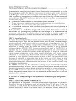
Fig. 3. Details of the EDR step at the Abrera DWTP.
produced through the EDR line. THMs's average values in the water product of the DWTP
ranged between 40 and 60 µg/L. The energetic average consumption for the EDR process
(stacks and pumps) has been lower than 0.6 kWh/m
3
. During the indicated period the
hydraulic performance has been higher than 90%, with a reduction of salts (measures like
conductivity) higher than 80% in summer. Specifics consumptions of HCl were of 0.08 Kg
HCl/m
3
and for antiscalant in the rejection of brine 0,002 Kg/m
3
(Valero et al., 2010)
Due to the large size of the industrial plant, additional R&D studies will be focused on O&M
procedures. Maintenance related to cleaning membranes and spacers, the measure of the
inter-membranes voltages and “hot spots” detection, would be simplified using specific
tools designed by the technical staff.
The cost of the new enlargement project was 61,218,478€. Given the considerable interest of
these works, their repercussion on the quality of the supply and the technology used, a
subsidy of 85% of the budget of the works was obtained from European Union funds.
6.2 Case study 2: The Depurbaix WWTP.
The project is located in Sant Boi de Llobregat, near Barcelona. It is a brackish water
desalination facility for some of the effluent treated in the Depurbaix WWTP, which
produces more than 57,000 m
3
/d using EDR technology (Segarra et al., 2009).
The facility is one of the largest in the world that treats wastewater for agricultural use. The
work was carried out by the Spanish temporary consortium BEFESA-ACSA using EDR
technology provided by MEGA a.s.
The main characteristics of the EDR system are:
• Inlet water: tertiary treatment of the WWTP + anthracite/sand filters. Average
conductivity 3.040 µS/cm
• Expected EDR product water: 55,296 m
3
/d.
• Expected plant product water after blending: 57,024 m
3
/d.
• Pump station : 2+1 pumps
Desalination, Trends and Technologies
16
• Cartridge filters: 4 filters with 300 cartridges each one (20 µm).
• 4 modules with 96 stacks with 600 cell pairs each one, in double stage.
• Heterogeneous ion-exchange membranes: RALEX AM(H) (anionic) and CM(H)
(cationic)
• Dry technologie
• Conductivity reduction: 60-80 %
• Water recovery>85%.
The plant started operating on a trial basis in January 2010 and came into the normal
operation from September 2010. The full automatic modular system allows the operation
according to the expected use of the product water.
Fig. 4. EDR stacks at the Depurbaix WWTP.
7. Discussion
In recent years membrane technology has become an important useful tool for the
desalination of seawater, the use of brackish water and polluted water resources which were
not suitable for producing drinking water, and for the physicochemical and microbiological
improvement of the water obtained by conventional treatment.
Based in the important advantatges of ion-exchange membranes (rugged, resistant to
organic fouling, chlorine stable, broad range for pH and Temperature, ) compared with
other membranes technologies, the improvement of EDR allows to use it for many
applications that are cost effective than other technologies with a better commercial
marketing like UF or RO. Maybe the use of EDR still has a label of a technology to solve
local problems involving small communities or specific industrial applications. However,
during last years big systems are in operation showing good performances and cost effective
results. In this sense the T. Maybry Carlton WTP located at Sarasota (FL, USA) was pioneer
in operate a big system since 1995. In that case, EDR was selected due to its ability to
Electrodialysis Technology - Theory and Applications
17
maximize recovery of freshwater and minimize wastewater volume. The plant produces
45.420 m
3
/d and is equipped with 320 stacks. Later, improvement of EDR allows installing
more systems worldwide, some of them in Spain related with drinking water and water
reuse. EDR was introduced in the Canary Islands during the 80’s, but during lasts years
some big facilities were building in the Spanish Mediterranean area: two plants (16,000
m
3
/d each) in Valencia to reduce nitrate levels and two more in Barcelona: the first to
reduce bromide levels and then the THMs formation (200.000 m
3
/d, 576 stacks) and the last
to reduce salinity for reuse water for irrigation (55.296 m
3
/d, 96 stacks).
In addition, desalination of brackish water using membranes technologies like ED and
specially EDR it is a cost effective method to supply good quality drinking water water and
could be a good solution for some industrial water utilities. Besides, EDR systems now are
simpler and more reliable, which means that the demineralization of difficult-to-treat water
is easier for municipalities to handle. In addition, the costs are becoming easier to swallow.
Some aspects could be improved in a near future: spacer configuration, membranes
chemistry, materials and configuration of electrodes, specific antiscalants for EDR,
elimination of degasifiers and the increase of the production of the stacks.
Finally, there are some interesting works related with the use of hybrid systems to get
synergies between technologies (Turek, 2002; Kahraman, 2004), and some innovations are
under study to improving the EDR technology (Balster et al., 2009; Charcosset, 2009; Ortiz et
al., 2008; Turek et al., 2008; Veerman et al., 2009).
8. Conclusions
• EDR should be effectively applied for water and salt recovery from an industrial
effluent for pollution prevention and for resource recovery.
• The growing popularity among municipalities of the EDR systems is related with its
capacity to reduce TDS and some inorganics elements like nitrates, sulphates, radon,
bromides and others, with high water recovery and easily operation and control by
adjusting amount of electricity applied to membrane stack.
• The correct operation of big EDR systems, compared with classical membrane pressure
systems like RO, allows extending EDR to new cost effective applications.
• Future steps of EDR systems could improve the design of membranes and spacers as
well as a more compact design, lowering the capital and O&M costs.
• EDR could be in a near future the technology of choice for many applications because
its efficiency to desalt water needed in differents fields like drinking water, reuse water
and many industrial applications, like food, beverages and mining among others.
• Hybrid systems between different membranes technologies including EDR, could be
useful solutions for specific applications, and could improve recovery and reduce
waste.
9. References
Asahi Chemical Industry Co. (October, 2010).www.asahi-kasei.co.jp
Asahi Glass Col. Ltd (October, 2010).www.agc.com
AWWA (1995). AWWA M38. Electrodialysis and Electrodialysis Reversal, American Water
Works Association, Denver, CO.
Desalination, Trends and Technologies
18
AWWA (2004). Committee report: current perspectives on residual management for
desalting membranes. J. AWWA, 96: 73-87.
Balster, J., D., Stamatialis D.F. & Wessling, M. (2009). Towards spacer free electrodialysis. J.
Memb. Sci. 341: 131-138.
Broens, L., Liebrand, N., Futselaar, H. & de Armas, J.C. (2004). Effluent reuse at Barranco
Seco (Spain): a 1,000 m
3
/h case study. Desalination 167: 13-16
Chang, E.E., Lin, Y.P. & Chiang, P.C. (2001). Effects of bromide on the formation of THMs
and HAAs. Chemosphere 43: 1029-1034.
Chao, Y.M. & Liang, T.M. (2008). A feasibility study of industrial wastewater recovery using
electrodialysis reversal. Desalination 221:433–439
Charcosset, C. (2009). A review of membrane processes and renewable energies for
desalination. Desalination 245: 214–231
Council Directive 98/83/EC of 3 November 1998 on the quality of water intended for
human consumption Official Journal L 330 , 05/12/1998 P. 0032 – 0054.
Dalla Costa R.F., Klein, C.W., Bernades A.M. & Ferreira, J.Z. (2002). Evaluation of the Electro
dialysis Process for the treatment of metal finishing wastewater. J. Braz.Chem. Soc.
Vol 13, Nº 4: 540-547.
De Barros, M. (2008). Avaliaçâo do processo de electrodiálise reversa no tratamento de
efluentes de refinaria de petróleo. PhD. Thesis, Escola de Engenharia, Universidade
federal do Rio Grande do Soul.
Devesa R., García V. & Matía, L. (2010). Water flavour improvement by membrane (RO and
EDR) treatment. Desalination, 250:113-117.
DuPont Co.(October, 2010).www.2dupont.com
Eurodia (October, 2010).www.eurodia.com
Fernandez-Turiel, J.L., Roig, A., Llorens, Antich, N., Carnicero, M. & Valero, F. (2000).
Monitorig of drinking water treatment plants of Ter and Llobregat (Barcelona NE
Spain) using ICP-MS, Toxicological and Environmental Chemistry 74: 87-103.
FuMA-Tech GmbH (October, 2010).www.fumatech.com
García, V., Fernández, A., Ferrer, O., Cortina, J.L., Valero, F. & Devesa, R. Aesthetic
assessment of blends between desalinated waters and conventional resources.
Proceedings of the IWA World Water Congress & Exhibition, Montreal 2010.
GE Water W&P. (October, 2010). www.ge.com
Harries R.C, Elyanow D., Heshka D.N. & Fischer K.L. (1991). Desalination of brackish
groundwater for a prairie community using electrodialysis reverersal. Desalination,
84: 109-121.
Hays, J. (2000).Iowa’s first electrodialysis reversal water treatment plant. Desalination, 132:
161-165.
Heshka, D. (1992). EDR water treatment desalination on the prairies. Desalination, 88: 109-
121.
Hidrodex. (October, 2010). www.hidrodex.com.br
Ionics Inc., (1984). Electrodialysis-Electrodialysis Reversal Technology, Ionics Inc.,
Watertown, MA.
Juda, W. & Mc Rae. W.A. (1950). Coherent ion-exchange gels and membranes. J. Am. Chem.
Soc., 72:1044.
Kahraman N., Cengel Y.A., Wood B, Cerci Y.(2004). Exergy analysis of a combined RO, NF,
and EDR desalination plant. Desalination, 171: 217-232.
Electrodialysis Technology - Theory and Applications
19
Kawahara, T. (1994). Construction and operation experience of a large-sacale electrodialysis
water desalination plant. Desalination, 96: 341-348.
Kimbrough, D.E. & Suffet, I.H. (2002) Electrochemical removal of bromide and reduction of
THM formation potential in drinking water. Water Res. 36: 4902-4906.
Korngold, E., Aronov, L. & Daltrophe, N. (2009). Electrodialysis of brine solutions
discharged from an RO plant. Desalination 242: 215–227
LanXess Sybron Chemicals (October, 2010).www.ionexchange.com
Larchet, C., Zabolotsky, V.I., Pismenskaya, N., Nikonenko, V.V., Tskhay, A., Tastanov, K. &
Pourcelly, G. (2008) Comparison of different ED stack conceptions when applied
for drinking water production from brackish waters. Desalination 222: 489–496.
Lee, H-J., Strathmann, H. & Moon, S-H. (2006). Determination of the limiting current density
in electrodialysis desalination as an empirical function of linear velocity.
Desalination 190: 43–50.
Lozier, J.C., Smith G., Chapman J.W. & Gattis D.E. (1992) Selection, design, and
procurement of a demineraliztion system for a surface water treatment plant.
Desalination 88: 3-31.
MEGA a.s. (October, 2010).www.mega.cz
Melnyk L. & Goncharuk V. (2009). Electrodialysis of solutions containing Mn (II) ions.
Desalination 241: 49-56.
Menkouchi Sahlia, M.A., Annouarb, S., Mountadarb, M., Soufianec, A. & Elmidaouia, A.
(2008). Nitrate removal of brackish underground water by chemical adsorption and
by electrodialysis. Desalination 227: 327–333
Mihara K. & Kato, M. (1969). Polarity reversing electrode units and electrical switching
means therefore, U.S.Patent 3,453,201.
Ortiz, J.M., Expósito, E., Gallud, F., García-García, V., Montiel, V. & Aldaz, A. (2008).
Desalination of underground brackishwaters using an electrodialysis system
powered directly by photovoltaic energy. Solar Energy Materials & Solar Cells
92:1677–1688.
PCA GmbH (October,2010).www.pccell.de
Pilat B.V. (2003). Industrial application of electrodialysis reversal systems. Desalination 158:
87-89.
Reahl E.R. Reclaiming reverse osmosis blowdown with electrodialysis reversal. (1990).
Desalination: 78, 1: 77-89.
Real Decreto 140/2003 de 7 de febrero de 2003 por el que se establecen los criterios
sanitarios de la calidad del agua de consumo humano. BOE 45, 7228-7245 (In
Spanish).
Roquebert, V., Booth, S., Cushing R.S., Crozes G., Hansen, E.(2000). Electrodialysis reversal
(EDR) and ion exchange as polishing treatment for perchlorate treatment.
Desalination 131: 285-291
Rook, J.J.(1977) Chlorination reactions of fulvic acids in natural waters. Environ. Sci &
Tecnol., 11:478-482.
Segarra, J., Iglesias, A., Pérez, J. & Salas, J. (2009). Construcción de la planta con mayor
capacidad de producción mundial con tecnología EDR para agues regeneradas.
Tecnología del Agua, 309: 56-62.
Desalination, Trends and Technologies
20
Schoeman, J.J. & Steyn, A. (2000) Evaluation of electrodialysis for water and salt recovery
from an industrial effluent. Proceedings of the WISA 2000 Biennial Conference, Sun
City, South Africa, 28 May - 1 June 2000
Strathmann, H. (2004). Ion Exchange membrana separation process. Elsevier, Ámsterdam.
Strathmann, H. (2010). Electrodialysis, a mature technology with a multitude of new
applications. Desalination, 264: 268-288.
Tecnoimpianti. (October, 2010). www.tecnoimp.com
Tianwei Membrane Co.Ltd. (October, 2010) www.sdtianwei.com
Tokuyama Co-Astom (October, 2010).www.tokuyama.co.jp
Tsiakis, P. & Papageorgiou, L.G. Optimal design of an electrodialysis brackish water
desalination plant. (2005). Desalination, 173: 173-186.
Turek, M. (2002). Dual-purpose desalination–salt production electrodialysis. Desalination
153:377–381
Turek, M., Bandura, B., Dydo, P. (2008). Power production from coal-mine brine utilizing
reversed electrodialysis Desalination 221: 462–466.
Valerdi-Pérez, R.M. & Ibáñez-Mengual, J.A. (2001).Current-voltage curves for an
electrodialysis reversal pilot plant : determination of limiting currents. Desalination
141 :23-37.
Valerdi-Pérez, R.M., López-Rodríguez, M. & Ibáñez-Mengual, J.A. (2001). Characterizing an
electrodialysis reversal pilot plant. Desalination 137 :199-206.
Valero, F., García, J.C., González, S., Medina, M.E., de Armas, J.C., Hernández, M.I. &
Rodríguez, J.J. (2007) Control of THMs at the Llobregat DWTP (NE, Spain) using
Electrodialisys Reversal (EDR). Abstract book, IDA World Congress-
Maspalomas,Gran Canaria –Spain. REF: IDAWC/MP07-207.
Valero, F., & Arbós, R. (2010). Desalination of brackish river water using Electrodialysis
reversal (EDR). Desalination, 253: 170-174.
Valero, F., Tous, J.F. & Arbós, R. (2010). Mejora de la calidad salnitaria del agua durante el
primer año de explotación de la etapa de electrodialisis reversible (EDR) en la
ETAP del Llobregat. Proceedings of the VII Congreso AEDYR, Barcelona octubre
2010.
Veerman J., Saakes M., Metz, S.J. & Harmsen, G.J. (2009).Reverse elecrodialysis: Performance
of a stack with 50 cells on the mixing of sea river water. J. Memb. Sci. 327: 136-144.
Winger, A.G., Bodamer, G.W. & Kunin, R. (1953) Some electrochemical properties of new
synthetic ion exchange memebranes. J. Electrochem. Soc. 100: 178.
Xu, T. (2005). Ion exchange membranes: state of their development and perspective. J.
Memb. Sci. 263:1-29.
2
Water Desalination by Membrane Distillation
Marek Gryta
West Pomeranian University of Technology, Szczecin
Poland
1. Introduction
Water is the most common substance in the world, however, 97% is seawater and only 3% is
fresh water. The availability of water for human consumption is decreasing due to
increasing the environmental pollution. According to the World Health Organisation
(WHO), about 2.4 billion people do not have access to basic sanitation facilities, and more
than one billion people do not have access to safe drinking water (Singh, 2006). Moreover,
the world’s population is expected to rise to nine billion from the current six billion in the
next 50 years. Chronic water pollution and growing economies are driving municipalities
and companies to consider the desalination as a solution to their water supply problems.
Generally, desalination processes can be categorized into two major types: 1) phase-
change/thermal and 2) membrane process separation. Some of the phase-change processes
include multi-stage flash, multiple effect boiling, vapour compression, freezing and solar
stills. The pressure driven membrane processes, such as reverse osmosis (RO), nanofiltration
(NF), ultrafiltration (UF) and microfiltration (MF), have found a wide application in water
treatment (Charcosset, 2009).
The energy required to run desalination plants remains a drawback. The energy limitations
of traditional separation processes provided the impetus for the development and the
commercialisation of membrane processes. Membrane technologies (simple, homogenous in
their basic concepts, flexible in application), might contribute to the solution of most of the
existing separation problems. Nowadays, membranes are used for the desalination of
seawater and brackish water, potable water production, and for treating industrial effluents.
RO membrane separation has been traditionally used for sweater desalination (Charcosset,
2009; Schäfer et al., 2005; Singh, 2006).
One of the limitations of membrane processes is severe loss of productivity due to
concentration polarisation and fouling or scaling (Baker & Dudley, 1998; Schäfer et al., 2005).
Membrane pretreatment processes are designed to minimise the potential problems of
scaling resulting from the precipitation of the slightly soluble ions. Membrane (MF or UF)
pretreatment of RO desalinations plants is now a viable options for removing suspended
solids, fine particles, colloids, and organic compounds (Banat & Jwaied, 2008; Singh, 2006).
NF pretreatment of sweater is also being used to soften RO feed water instead of traditional
softening (Schäfer et al., 2005).
The industrial development of new membrane processes, such as membrane distillation
(MD), is now being observed (Banat & Jwaied, 2008; Gryta, 2007). In MD process feed water
is heated to increase its vapour pressure, which generates the difference between the partial
Desalination, Trends and Technologies
22
pressure at both sides of the membrane (El-Bourawi et al., 2006). Hot water evaporates
through non-wetted pores of hydrophobic membranes, which cannot be wetted by liquid
water (Gryta & Barancewicz, 2010). The passing vapour is then condensed on a cooler
surface to produce fresh water (Alklaibi & Lior, 2005; Charcosset, 2009). In the case of
solutions of non-volatile substances only water vapour is transported through the
membrane. Thus, MD process has a potential application for the water desalination and the
treatment of wastewater (Banat et al., 2007; El-Bourawi et al., 2006; Wang, et al., 2008). The
MD has a significantly lower requirements concerning pretreatment of feed water, therefore,
it enables the production of pure water from water sources, the quality of which impedes a
direct application of the RO for this purpose. However, the feed usually contains various
impurities, which in turn lead to the formation of deposit (Gryta, 2008). Deposits both
pollute surfaces of membranes and make it easier for water to penetrate membrane pores
(Gryta, 2007b; He et al., 2008). Consequently, membranes lose their separation properties
and the MD process stops. This is why it is essential to prevent formation of deposits on the
membrane surfaces.
2. Principles of membrane distillation
An expanded definition of MD process was created in 1986 at the “Workshop on Membrane
Distillation” in Rome (Smolder & Franken, 1989). The term “Membrane Distillation” should
be applied for membrane operations having the following characteristics:
- the membrane should be porous and not be wetted by the process liquids;
- no capillary condensation should take place inside the pores of the membrane;
- only vapour should be transported through the pores;
- the membrane must not alter the vapour-liquid equilibrium of the different components
in the process liquids;
- at least one side of the membrane should be in direct contact with the process liquid;
- the driving force for each component is a partial pressure gradient in the vapour phase.
In membrane distillation heat is required to evaporate the feed components, therefore, in
such context (similarly as in the classical distillation) it can be concluded that MD is a
thermal-diffusion driven process. However, it operates at low temperatures (323-363 K),
therefore, the feed water can be heated be using renewable energy (Banat & Jwaied, 2008).
The MD is carried out in various modes differing in a way of permeate collection, the mass
transfer mechanism through the membrane, and the reason for driving force formation
(Gryta, 2005; Smolder & Franken, 1989). These differences were taken into consideration in
the nomenclature by the addition to the term “Membrane Distillation” the words, which
emphasised a feature of a given variant. Various types of MD are known for several years
(Fig.1): direct contact MD (DCMD), air gap MD (AGMD), sweeping gas MD (SGMD) and
vacuum MD (VMD). DCMD variant is the most frequently studied and described mode of
MD process (Alklaibi & Lior, 2005; El-Bourawi et al., 2006; Gryta, 2010; Wang, et al., 2008).
Several theoretical mass transfer models have been presented to describe membrane
distillation. The models of DCMD were based on the assumption that vapour permeates
through the porous membrane, as a result of molecular diffusion, Knudsen flow and/or the
transition between them (Alklaibi & Lior, 2005; El-Bourawi et al., 2006; Gryta, 2008). Using
the Stefan-Maxwell model diffusion of vapour through the air layer, the permeate flux can
be described as proportional to the membrane permeability and water partial pressure
difference (Alklaibi & Lior, 2007; Gryta et al., 1998):
Water Desalination by Membrane Distillation
23
()
DF
inm
W
m
WA
V
pp
p T R
P M
sχ
D ε
J −= (1)
where p
F
and p
D
are the partial pressures of the saturated water vapour at interfacial
temperatures T
1
and T
2
; ε , χ, s
m
, M
W
, R, T
m
, P, D
WA
and p
in
are membrane porosity, pore
tortousity, membrane thickness, molecular weight, gas constant, membrane temperature,
total pressure, vapour diffusion coefficient and air concentration inside the pores,
respectively.
membrane
Cold
distillate
A) B)
C) D)
vacuum
Vapour
Sweeping
gas
Va
p
our
Hot
seawater
membrane
Hot
seawater
Cooling
water
vapour
Hot
seawater
Hot
seawater
Fig. 1. Types of membrane distillation: A) DCMD, B) AGMD, C) VMD, D) SGMD
In MD process the mass transfer (J
V
) occur simultaneously with heat conduction (Q) across
the membrane material, and as a results, the temperature of the boundary layer on the feed
side is lower, whereas on the distillate side it is higher than that of the bulk (Fig.2). This
phenomenon is termed as the temperature polarization (Martínez-Díez & Vázquez-
González, 1999). It causes the decrease of vapour pressure difference across the membrane
which leads to the reduction of the magnitude of the mass flux (permeate) flowing through
the membrane. The interfacial temperatures T
1
and T
2
cannot be measured directly. Several
equations used to calculate these temperatures have been presented in the MD literature
(Gryta et al., 1998; Khayet et al., 2004; Srisurichan et al., 2006). Their values depend in
essential way on the conditions of a heat exchange in the MD module. Thus the correct
description of the heat transport across the membrane will determine the accuracy of the
mathematical calculation of MD process run (El-Bourawi et al., 2006; Gryta et al., 1998;
Gryta, 2008).
Desalination, Trends and Technologies
24
Q
T
1
J
V
T
F
T
2
T
D
Δ
p
p
D
p
F
membrane
Distillate
Feed
Δ
Τ
Fig. 2. Principles of DCMD: T
1
, T
2
, T
F
, T
D
— temperatures at both sides of the membrane,
and temperatures of feed and distillate, respectively; p
F
, p
D
— water vapor partial pressure
at the feed and distillate sides, respectively
2.1 Membranes and modules
The porous and hydrophobic MD membranes are not selective and their pores are filled
only by the gas phase. This creates a vapour gap between the feed and the produced
distillate, what is necessary for MD process operation. However, during the MD a part of
the membrane pores may be wetted, that decreases a thickness of vapour gap inside the
membrane wall (Gryta & Barancewicz, 2010). Therefore, the properties of membrane
material and membrane porous structure are important for MD process performance
(Bonyadi & Chung, 2009; Khayet et al., 2006).
Membrane for MD process should be highly porous, hydrophobic, exhibit a desirable
thermal stability and chemical resistance to feed solution (El-Bourawi et al., Gryta et al.,
2009). These requirements are mostly fulfilled by the membranes prepared from polymers
with a low value of the surface energy such as polytetrafluoroethylene (PTFE),
polypropylene (PP) or poly(vinylidene fluoride) (PVDF) (El Fray & Gryta, 2008; Gryta, 2008;
Li & Sirkar, 2004; Teoh et al., 2008; Tomaszewska, 1996). Apart from the hydrophobic
character of the membrane material, also the liquid surface tension, pores diameter and the
hydraulic pressure decide about the possibility of the liquid penetration into the pores. This
relation is described by the Laplace – Young (Kelvin law) equation (Schneider et al., 1988):
p
DF
d
Θ cosσ B 4
PPΔP
−
=−=
(2)
where: ΔP is liquid entry pressure (LEP), B is the pore geometry coefficient (B = 1 for
cylindrical pores), σ is the surface tension of the liquid, Θ is the liquid contact angle, d
P
is the
diameter of the pores, P
F
and P
D
are the hydraulic pressure on the feed and distillate side,
respectively. Water and the solutions of inorganic compounds have high surface tension (σ
> 72x10
–3
N/m), however, when the organics are present, its value diminishes rapidly. Thus,
taking into consideration the possibility of membrane wetting, it is recommended that for
MD the maximum diameter of membrane pores does not exceed the 0.5 μm (Gryta, 2007b;
Gryta & Barancewicz, 2010; Schneider et al., 1988).
Water Desalination by Membrane Distillation
25
Hydrophobic polymers are usually low reactive and stable, but the formation of the
hydrophilic groups on their surface is sometimes observed (Gryta et al., 2009). The surface
reactions usually create a more hydrophilic polymer matrix, which may facilitate the
membrane wettability (El Fray & Gryta, 2008; Khayet & Matsuura, 2003). The amount of
hydrophilic groups can be also increased during MD process and their presence leads to an
increase the membrane wettability (Gryta et al., 2009; Gryta & Barancewicz, 2010).
The application of membranes with improved hydrophobic properties allows to reduce the
rate of membrane wettability. Blending of PTFE particles into a spinning solution modified
the PVDF membrane, and enhances the hydrophobicity of prepared membranes (Teoh &
Chung, 2009). Moreover, the resistance to wetting can be improved by the preparation of
MD membranes with the uniform sponge-like membrane structure (Gryta & Barancewicz,
2010).
Apart from membrane properties, the MD performance also depends on the module design.
The capillary modules can offer several significant advantages in comparison with the plate
modules (flat sheet membranes), such as a simple construction and suppression of the
temperature polarization (El-Bourawi et al., 2006; Gryta, 2007; He et al., 2008; Li & Sirkar,
2004; Teoh et al., 2008). The efficiency of the MD capillary module is significantly affected by
the mode of the membranes arrangement within the housing (Fig. 3).
330 340 350 360 370
0
100
200
300
400
500
Permeate flux, J
V
[dm
3
/m
2
d]
Feed temperature, T
F
[K]
M1
M2
M3
Fig. 3. The influence of feed temperature and the mode of membrane arrangement in a
capillary module on the permeate flux. M1 - bundle of parallel membranes; M2 - braided
capillaries; and M3 – capillaries mounted inside mesh of sieve baffles
The driving force for the mass transfer increases with increasing the feed temperature,
therefore, the permeate flux is also increased at higher feed temperatures. A traditional
construction (module M1) based upon the fixation of a bundle of parallel membranes solely
at their ends results in that the membranes arrange themselves in a random way. This
creates the unfavourable conditions of cooling of the membrane surface by the distillate,
which resulted in a decrease of the module efficiency. In module M3 the membranes were
Desalination, Trends and Technologies
26
positioned in every second mesh of six sieve baffles, arranged across the housing with in
0.1–0.15 m. The most advantageous operating conditions of MD module were obtained with
the membranes arranged in a form of braided capillaries (module M2). This membrane
arrangement improves the hydrodynamic conditions (shape of braided membranes acted as
a static mixer), and as a consequence, the module yield was enhanced.
2.2 MD process efficiency
Although the potentialities of MD process are well recognised, its application on industrial
scale is limited by the energy requirements associated. Therefore, high fluxes must be
obtained with moderate energy consumption. DCMD has been widely recognised as cost-
efficient for desalination operating at higher temperatures, when waste heat is employed to
power the process (Alklaibi & Lior, 2005). The performance of membrane distillation mainly
depends on the membrane properties, the module design and it operating conditions (Bui et
al., 2010; Li & Sirkar, 2004).
Concerning the operating conditions (Figs. 3 and 4), the feed temperature has the most
significant influence on the permeate flux, followed by the feed flow rate and the partial
pressure established at the permeate side. This last depending on the distillate temperature
for DCMD and on the vacuum applied for VMD (Criscuoli et al, 2008; El-Bourawi et al.,
2006).
The results presented in Fig. 4 confirmed that the distillate velocities had a minor role in
improving the mass transfer, but a distillate velocity below 0.3 m/s would cause a rapid
decrease in mass flux (Bui et al., 2010). Moreover, Bui et al. were indicated, that the distillate
temperature has had a significant greater influence on DCMD energy efficiency. It is known
that decreasing the water temperature from 283 to 273 K results in a very small an increase
of mass driving force. Therefore, it is recommended that the DCMD process be operated at a
distillate temperature higher than 283 K.
0.2
0.4
0.6
0.8
1
300
400
500
600
700
800
Permeate flux J
V
[dm
3
/m
2
d]
Feed flow rate, v
F
[m/s]
v
D
[m/s]:
- 0.26
- 0.38
- 0.72
Fig. 4. The effect of the flow rate of streams in a module with braided membranes (module
M1) on the permeate flux. T
F
= 353 K, T
D
= 293 K
Water Desalination by Membrane Distillation
27
The viability of MD process depends on an efficient use of available energy. The heat
transfer inside the membrane (Q – total heat) takes place by two possible mechanisms, as
conduction across the membrane material (Q
C
) and as latent heat associated with vapour
flowing through the membrane (Q
V
). The heat efficiency (η
T
) in the MD process can be
defined by Eq. 3.
CV
VV
T
Q
Q
Q
η
+
== (3)
The heat transfer which occurs in MD module leads to a cooling of the hot feed and to a
heating of the distillate. Therefore, in the DCMD process it is necessary to supply heat to the
hot stream and to remove heat from the distillate stream. The heating and the cooling steps
represent the energy requirements of the DCMD process.
The amount of heat exchanged in the MD module increases along with an increase of the
feed temperature (Fig. 5). However, under these conditions the permeate flux also increases,
which causes the limitation of heat losses (heat conducted through the membrane material).
As a results, an increase in the module yield influences on the enhancement of heat
efficiency of the MD process (Fig. 6). For the highest permeate flux the η
T
coefficient equal to
0.75 was obtained. It was concluded that energy efficiency of DCMD process could be
maximised if the process were operated at the highest allowable feed temperature and
velocity (Bui et al., 2010). A nonuniform arrangement of the capillary membranes in the
module housing (module M1) caused a decrease in the energy consumption efficiency.
The unitary energy consumption in the MD process decreases along with temperature of
feeding solution. This consumption was reduced from 5000 to 3000 kJ per 1 kg of obtained
distillate when the feed temperature increased from 333 to 363 K (Gryta, 2006).
A decrease of the membrane wall thickness significantly increases the obtained permeate
flux. However, during the MD process the liquid systematically wetted the consecutives
pores, which reduced the thickness of the air-layer inside the membrane wall. In this
330 340 350 360 370
0
100
200
300
400
500
T
D
= 293 K
- module M1
- module M2
Permeate flux, J
V
[dm
3
/m
2
d]
Feed temperature, T
F
[K]
Total heat, Q [kW/m
2
]
20
6
8
10
12
14
16
18
Fig. 5. Effect of feed inlet temperature and mode of membrane arrangement (M1 - parallel,
irregular, M2 – braided membranes) on permeate flux and heat transfer in DCMD
Desalination, Trends and Technologies
28
T
D
= 293 K
– module M1
– module M2
2
3
4
5
6
330 340 350 360 370
Feed temperature, T
F
[K]
Heat conducted, Q
C
[kW/m
2
]
0.4
0.5
0.6
0.7
0.8
Heat efficiency
,
η
T
Fig. 6. Effect of feed temperature and mode of membrane arrangement (M1 - parallel,
irregular, M2 – braided membranes) on heat conducted and heat efficiency in DCMD
situation, the membranes having a thin wall will be wetted in a relatively short time.
Therefore, the hydrophobic membranes with thicker walls are recommended for
commercial DCMD applications (Gryta & Barancewicz, 2010).
3. Membranes fouling
Fouling is identified as a decrease of the membrane permeability (permeate flux) due to
deposition of suspended or dissolved substances on the membrane surface and/or within
its pores (Schäfer et al., 2005). Several types of fouling can occur in the membrane systems,
e.g. inorganic fouling or scaling, particulate and colloidal fouling, organic fouling and
biological fouling (Baker & Dudley, 1998; Singh, 2006; Srisurichan et al., 2005). Scaling
occurs in a membrane process when the ionic product of sparingly soluble salt in the
concentrate feed exceeds its equilibrium solubility product. The term scaling is commonly
used when the hard scales are formed (e.g. CaCO
3
, CaSO
4
) (He et al., 2008; Lee & Lee, 2000).
Fouling is also one of the major obstacles in MD process because the deposit layer formed
on the membrane surface may cause membrane wetting. This phenomenon will certainly be
accelerated if the salt crystals were formed inside the pores (Alklaibi & Lior, 2005; Gryta,
2002; Gryta, 2007; Tun et al., 2005).
The possible origins of fouling in MD process as follows: chemical reaction of solutes at the
membrane boundary layer (e.g. formation of ferric hydroxides from soluble forms of iron),
precipitation of compounds which solubility product was exceeded (scaling), adsorption of
organic compounds by membrane-forming polymer, irreversible gel formation of
macromolecular substances and colonization by bacteria and fungi (Gryta, 2002; Gryta,
2005b; Gryta, 2007; Gryta, 2008). The operating conditions of membrane distillation
restricted the microbial growth in the MD installation; therefore, one should not expect the
problems associated with biofouling in the degree encountered in other membrane
processes such as UF, NF or RO (Gryta, 2002b).
A large influence on the fouling intensity has a level of feed temperature. During concentration
of bovine serum albumin aqueous solution by DCMD was found that fouling was practically
Water Desalination by Membrane Distillation
29
absent in the process operated at low temperature (i.e. 293–311 K) (Ortiz de Zárate et al., 1998).
On the contrary, a severe fouling by proteins was observed at higher feed temperatures (Gryta
et al., 2001; Gryta et al., 2006c). The CaCO
3
scaling is also increased with an increase of the feed
temperature. As a result of feed heating the HCO
3
–
ions, present in the water, undergo the
decomposition and a significant amount of CaCO
3
precipitates on the membrane surface
(Drioli et al., 2004; Karakulski & Gryta, 2005; Gryta, 2005b; Schneider, et al., 1988). Although
the acidification of feed water to pH 4 limited CaCO
3
scaling in the MD process, a slight
fouling caused by other compounds (such as silicates), was still observed (Karakulski & Gryta,
2005). The foulants concentration may be reduced in the pretreatment stage, e.g. by using the
NF or RO processes (Karakulski et al, 2002; Gryta, 2005b).
The deposit layers can be divided into two basic categories: porous and homogenous (non-
porous) - Fig. 7. The deposit covered a part of the membrane surfaces, which reduced the
membrane permeability and changed the temperature polarisation (Gryta, 2007). The values
of heat transfer coefficients in both liquid phases and the membrane have a dominant
influence on the values of T
1
and T
2
temperature of surfaces adjacent to the membrane
(Fig. 2). The deposit layer creates an additional thermal resistance, thus decreasing the heat
transfer coefficient from the feed bulk to the evaporation and condensation surfaces, and the
temperature polarisation increased. As a result, the driving force for mass transfer is
reduced and a significant decline of the permeate flux was observed (Gryta, 2008). The
formation of non-porous layer causes a significant increase in the mass transfer resistance
and the value of the permeate flux approach zero in an exponential way (Gryta, 2008).
Fig. 7. SEM image of deposit on the MD membranes (Accurel PP S6/2). A) porous (CaCO
3
);
B) non-porous (proteins)
The supersaturation state enables the nucleation and crystal growth, what in MD is mainly
caused by water evaporation and temperature changes (Alklaibi & Lior, 2005; Gryta, 2002;
He et al., 2008; Yun et al., 2006). In the case when the solute solubility decreases along with a
temperature drop, deposit can be formed as a result of the temperature polarization (He et
al., 2008; Gryta, 2002).
The formation of deposit on the MD membrane surface begins in the largest pores (Fig. 8),
because they undergo wettability the most rapidly (Alklaibi & Lior, 2005; Schneider et al.,
1988). The wetted pores are filled by the feed, what facilitates the oversaturation and
formation of deposits. The salt crystallization inside the pores was limited through a
reduction of the surface porosity (Gryta, 2007b; He et al., 2008).
Desalination, Trends and Technologies
30
Fig. 8. SEM images of deposits formed inside the large pores (3-5 μm of diameter)
The adherence of the deposit to the membrane surface is a critical factor for MD
performance, as well as for other membrane processes (Gryta, 2008; Gryta, 2009). It was
found, that the deposit of CaCO
3
on the membrane surface can easily be removed by rinsing
the module with a 2–5 wt.% solution of HCl, what allowed to restore the initial permeate
flux (Fig. 9). However, the repetitions of module cleaning procedure by this method resulted
in a gradual decline of the maximum permeate flux (Gryta, 2008).
200 6000 800
1000
200
300
400
500
600
700
800
Time of MD process, t [h]
Permeate flux, J
V
[dm
3
/m
2
d]
Module rinsin
g
– 3 wt.% HCl
400
Fig. 9. Changes of the permeate flux during MD process of tap water
The SEM investigation of the membrane cross-sections revealed that the deposit covered not
only the membrane surfaces but also penetrated into the pore interior (Fig. 10). The SEM-
EDS line analysis of a change of the calcium content located into the membrane wall
demonstrated that the deposit occurred up to the depth of 20–30 μm. Although, a rinsing
acid solution dissolves the crystals, the wettability of the pores filled by deposit was
accompanied to this operation. Therefore, the elimination of the scaling phenomenon is very
important for MD process. The application of chemical water softening and the net filters
(surface crystallization) allows to limit the amounts of precipitates deposited on the
membrane surface during water desalination by MD process (Gryta, 2008c).
Water Desalination by Membrane Distillation
31
a)
A
0 10 20 30 40
Distance, L [μm]
Ca
b)
Fig. 10. CaCO
3
deposit on the membrane surface. a) membrane cross section, b) SEM-EDS
line analysis (direction A)
4. Water pretreatment and membrane cleaning
The main techniques currently used to control fouling are feed pretreatment and membrane
cleaning (Baker & Dudley, 1998; Schäfer et al., 2005, Gryta, 2008). The degree of
pretreatment depends on the nature of the feeding water, the kind of membrane, the water
recovery level and frequency of membrane cleaning (Karakulski et al., 2006; Schäfer et al.,
2005). It was found that a significant amount of foulants from effluents obtained during ion-
exchangers regeneration was successfully removed by the addition of the Ca(OH)
2
to treated
wastewater (Gryta et al., 2005c). The fouling intensity can be also limited by combining the
MD with other membrane processes (Drioli et al., 2004; Jiao, 2004; Karakulski et al., 2006).
The UF/MD integrated processes enables the concentration of solutions polluted by
significant amounts of petroleum derivatives (Karakulski et al., 2002; Gryta et al., 2001b). On
the other hand, an excessively advanced pretreatment system significantly increases the
installation costs (Karakulski et al., 2006), which may render the application of MD process
as unprofitable. Moreover, an effective water pretreatment by NF and RO processes did not
allow to completely eliminate fouling (Karakulski et al., 2002; Karakulski & Gryta, 2005),
therefore, its negative consequences should also be limited through the development of
appropriate procedure of installation operation.
The majority of problems encountered during the water desalination by MD process are
associated with water hardness. As the water is heated, CO
2
content decreases and the
precipitation of CaCO
3
takes place due to the decomposition of bicarbonate ions (Figs. 7–11).
For this reason, the feed water has to be pretreated before feeding the MD installation
(Singh, 2006; Karakulski et al., 2006; Gryta, 2006b). Several operations such as coagulation,
softening and filtration are used during the production of technological water. The
possibility of such pretreated water utilization as a feed for the MD process is an attractive
option (Gryta, 2008b). Contact clarifiers (accelators) are usually applied to the chemical
pretreatment of feed water in power stations (Powell, 1954, Singh, 2006). The chemicals (e.g.
lime, aluminum or ferric sulphate) are added directly to the accelator containing a relatively
high concentration of precipitated sludge near the bottom of the tank, and raw water is
treated with this mixture. Inside the accelator, water flowing downward from the mixing
and reaction zone passes the outer section of a much larger diameter, which is free of
turbulence. Subsequently, the water flows upward, and the removal of flocks by settling
takes place. A larger portion of this water passes through the return zone to the primary
mixing and to the reaction zone. This recirculation improves the quality of the treated water.
Desalination, Trends and Technologies
32
Fig. 11. SEM images of CaCO
3
deposit on membrane surface after: A) 10 h, and B) 50 h
desalination of surface water by MD process
Fe
2
(SO
4
)
3
Ca(OH)
2
raw
water
clean
water
sludge
Fig. 12. Water treatment using the contact clarifiers (accelator)
The chemical pretreatment of ground water caused a significant decrease of the
concentration of compounds responsible for the formation of a deposit on the membrane
surface during the MD process (Gryta, 2008). However, the treatment of water carried out in
an accelator, employed in the power station for production of demineralized water by the
ion exchange process, was found to be insufficient for the MD process (Fig. 13). The
formation of crystallites on the membrane surface was confirmed by SEM observations.
Thus, a further purification of water produced by accelator is required in order to use it as a
feed for the MD process.
A very efficient method for preventing CaCO
3
precipitation is dosing an acid (Karakulski &
Gryta, 2005). In this case HCO
3
–
ions are converted into CO
2
according to the following
reaction:
HCO
3
–
+ H
+
→ CO
2
+ H
2
O (4)
A major disadvantage of this method is an increase of concentration of chloride (HCl) or
sulphates (H
2
SO
4
) in the retentate. The later anions (SO
4
–2
) are particularly hazardous for the
membrane (Fig. 14).
Water Desalination by Membrane Distillation
33
0 50 100 150 200 250 300
300
400
500
600
700
Time of MD process, t [h]
raw water
pretreated water (accelator)
Permeate flux, J
V
[dm
3
/m
2
d]
Fig. 13. Effect of the feed pretreatment (accelator) on the MD permeate flux
Fig. 14. SEM image of CaSO
4
deposit on the MD membrane surface
Sulphates comprise the second type of fouling components, the scaling of which can be
encountered during water desalination by MD. The CaSO
4
solubility often determines the
maximum recovery rate of demineralised water from feeding water (Gryta, 2009b).
The feed water before flowing into MD modules is heated in heat exchangers. In this case, a
thermal softening of water can also be performed (Gryta, 2006b). As the water is heated, CO
2
content decreases and the precipitation of CaCO
3
takes place due to the decomposition of
bicarbonate ions. A precipitated deposit may also cause substantial fouling of membranes;
therefore, this deposit should be removed by using an additional filtration (Karakulski &
Gryta, 2005). Other option is the application of heat exchanger, the design of which allows to
remove the deposit of carbonates formed during water heating (Gryta, 2004).
Thermal pretreatment allows to remove most bicarbonates from water, which in turn
reduces the amount of precipitate forming during MD process. However, the degree of
water purification sometimes is too low and precipitate is still forming on the membrane
surface. The SEM-EDS analysis revealed that apart a large amount of Ca, this deposit also
contained Mg, Si, S, Fe, Ni, Al and Na. When the majority of HCO
3
–
ions was removed from
water, the carbonates formed an amorphous deposit with increased content of silicon
(Gryta, 2010b). Such a nonporous form of deposit increases the rate of decline of the MD
Desalination, Trends and Technologies
34
process efficiency (Fig. 15). For this reason an additional operation of the feed treatment was
required to prevent the formation of deposit. The residual of HCO
3
–
ions, from the thermally
softened water, were removed by acidifying the boiled water down to pH = 4. This
operation retained the formation of precipitate and as a result the MD process proceeded
without the flux decrease.
0 50 100 150 200
300
400
500
600
700
-tap water
- boiled tap water
- boiled water+HCl
Time of MD, t [h]
Permeate flux, J
V
[dm
3
/m
2
d]
Fig. 15. The dependence of permeate flux as a function of the mode of feed pretreatment
Increasing the speed of the feed flow can reduce the negative influence deposit formation on
MD process efficiency. SEM investigations demonstrated that the layer of the deposit was
in this case more porous (Gryta, 2008c).
The induction period of CaCO
3
nucleation decreases as the supersaturation increases, but
for the low saturation ratios (5-20) the induction period was higher than 30 min. It was
reported that the induction time decreased from 12.9 to 1.1 min when the saturation ratio
increased from 4 to 16 (Qu et al.; 2009). The elimination of membrane scaling is possible
when the induction time will be longer than the residue time of feed inside the MD module.
A heterogeneous crystallization performed inside a net filter may decrease the saturation
ratio and as a result, the amount of deposit formed on the membrane surface will be
reduced (Gryta, 2006b). The application of pre-filter element assembled directly to the MD
module inlet allows to significantly limit the amounts of precipitates deposited on the
membrane surface during the desalination of natural water by MD process (Gryta, 2009c).
The removal of formed deposit from this element (rinsing by HCl solutions) would not
result in the membrane wettability. The period between consecutive rinsing operations of
the pre-filter is dependent on the several factors, such as a water hardness level, parameters
of MD process and the residence time of the feed inside the MD installation. On the basis of
the obtained results it can be assumed, that this period would be in the range of 2–5 h. The
efficiency of this system was found to decrease along with an increase of distance of pre-
filter element from the module inlet.
5. Practical aspects of MD process
The MD separation mechanism is based on vapour/liquid equilibrium of a liquid mixture.
For solutions containing non-volatile solutes only water vapour is transferred through the
membrane; hence, the obtained distillate comprises demineralized water (Alklaibi & Lior,
2005; Karakulski & Gryta, 2005; Schneider et al., 1988). However, when the feed contains
Water Desalination by Membrane Distillation
35
several volatile components, they are also transferred through the membranes to the
distillate (El-Bourawi et al., 2006; Gryta, 2010c). Based on this separation mechanism, the
major application areas of membrane distillation include water treatment technology,
seawater desalination, production of high purity water and the concentration of aqueous
solutions (El-Bourawi et al., 2006; Drioli et al. 2004; Gryta et al., 2005c; He et al., 2008;
Karakulski et al., 2006, Li & Sirkar, 2005; Srisurichan et al., 2005; Teoh et al., 2008).
0 50 100 150 200 250
0
2
4
6
8
10
12
Time of MD, t [h]
0
0.5
1
1.5
2
2.5
C
Feed
[g TDS/dm
3
]
κ
permeate
[μS/cm]
0 50 100 150 200
0
5
10
15
20
0
0.3
0.4
0.5
0.6
0.7
Time of MD, t [h]
Feed, IC and TOC [ppm]
Distillate, TOC [ppm]
IC
TOC
Fig. 16. Desalination of surface water by MD process
The results shown in Fig. 16 indicate that an increase in the feed concentration had a
negligible effect on the quality of produced distillate. Despite the increasing value of the
feed concentration the content of inorganic carbon (IC) in the distillate was close to the
analytic zero. Only a slight amount of total organic carbon (TOC), below 0.5 mg TOC/dm
3
,
was detected in the distillate, which can be associated with the transport of the volatile
compounds through the MD membranes. It was found that volatile organic compounds
(VOCs) diffuse through the pores of hydrophobic membranes, similarly to water vapour,
hence, they are not completely rejected in the MD process (Gryta, 2010c; Karakulski &
Gryta, 2005; Lawson & Loyd, 1997).
The produced MD distillate usually has the electrical conductivity in the range 0.5–5
μS/cm
and contained below 0.5 ppm of inorganic carbon. It confirms the fact that regardless of the
time of the process duration
, the MD membranes demonstrated a high retention of inorganic
solutes (Alklaibi et al., 2005; Gryta, 2006b).
The possibility of application of the MD process for the treatment of saline effluents
generated during the regeneration of ion exchangers was investigated. The feasibility
studies were also performed in the MD pilot plant (Gryta, 2007). A corrosion phenomenon
was noticed in this installation during a long-term operation of process. The pilot plant was
constructed using a typical heat exchanger made of stainless steel, however, the employed
construction material was found to undergo the corrosion in studied solutions. A more
appropriate heat exchangers for this process should be made of tantalum, but their price is
2-times higher than the cost of constructed MD installation. Therefore, the treatment of the
effluents from ion exchangers regeneration would be unprofitable due to a high investment
cost. Moreover, the fouling caused by iron oxides does not always result from the corrosion
of installation, but also from the reactions proceeding in the feed. Therefore, the utilization
of plastics for the construction of the entire MD installation will not prevent the formation of
iron oxides that subsequently will precipitate onto the membrane surface. Such a
Desalination, Trends and Technologies
36
phenomenon has been observed in the hybrid MD/absorber system utilised for gas
purification by the absorption of SO
2
in a solution of Fe (II) sulphate (VI) proceeding
simultaneous with the catalytic oxidation of SO
2
to sulphuric acid (Lewicki & Gryta, 2004).
Membrane processes associated with renewable energy for water desalination offer
alternative solutions to decrease the dependence on fossil fuels (Charcosset, 2009). The
potential use of solar thermal-driven MD process for water desalination has been studied
extensively. Although the desalted water was produced using free energy, it was stated that
this technology is still expensive compared to other desalination processes (Banat & Jwaied,
2008). However, it was found that increasing the reliability of the MD technology and plant
life-time could reduce the cost of the produced water significantly.
6. Conclusion
In comparison with other desalination processes, the main advantages of membrane
distillation are: (1) 100% separation (in theory) of ions, macromolecules, colloids, cells etc.,
(2) lower operating pressures, (3) lower requirements concerning the mechanical properties
of the membrane, and (4) less space requirement compared to conventional distillation
processes. However, besides these advantages, membrane distillation still faces difficulties
for commercialization.
The availability of the industrial MD modules is currently one of the limitations for MD
process implementation. Flat-sheet membranes in plate and frame modules or spiral wound
modules and capillary membranes in tubular modules have been used in various MD
studies. The design of the MD modules should provide not only good flow conditions, but
also has to improve the heat transfer and thermal stability. Several advantages offer the
capillary MD modules. The efficiency of these modules was significantly improved when
the cross flow or a devices with membranes arranged in a twisted or braided form in the
housing were used.
The major difficulties are basically associated with a phenomenon of membrane wetting and
the formation of the deposit on its surface. The use of an adapted pretreatment minimizes
the fouling problems and can provide good protection of the membranes. Moreover, the
module scaling may be reduced using the appropriate MD process conditions. The CaCO
3
precipitation was limited by lowering the feed temperature and by increasing the feed flow
rate. The HCO
3
–
ions concentration may be reduced by chemical water softening or by using
pressure driven membrane processes. An effective solution would be the complete removal
of the HCO
3
–
ions from feed water, which can be achieved by the acidification of water to
pH 4. However, the significant amounts of acids are required for feed acidification and as a
result, the amount of salt increased in the retentate discharged to the environment.
The fouling and scaling accelerated the membrane wetting; therefore, more work will have
to be done for a thorough evaluation of these phenomena.
7. References
Alklaibi, A.M. & Lior, N. (2005). Membrane-distillation desalination: status and potential,
Desalination, Vol. 171, No. 2 (January 2005) 111–131, ISSN 0011-9164
Alklaibi, A.M. & Lior, N. (2007). Comparative study of direct-contact and air-gap membrane
distillation processes.
Ind. Eng. Chem. Res. Vol.46, No.2 (January 2007) 584–590,
ISSN
Water Desalination by Membrane Distillation
37
Baker, J.S. & Dudley L.Y. (1998). Biofouling in membrane system - A review. Desalination,
Vol. 18, No.1-3 (September 1998) 81–90, ISSN 0011-9164
Banat, F.; Jwaied, N.; Rommel, M.; Koschikowski. J. & Wieghaus, M. (2007). Performance
evaluation of the “large SMADES” autonomous desalination solar-driven
membrane distillation plant in Aqaba, Jordan.
Desalination, Vol.217, No.1-3,
(November 2007) 17-28, ISSN 0011-9164
Banat, F. & Jwaied, N. (2008). Economic evaluation of desalination by small-scale
autonomous solar-powered membrane distillation units.
Desalination, Vol.220,
No.1-3, (March 2008) 566–573, ISSN 0011-9164
Bonyadi, S. & Chung, T.S. (2009). Highly porous and macrovoid-free PVDF hollow fiber
membranes for membrane distillation by a solvent-dope solution co-extrusion
approach,
J. Membr. Sci., Vol. 331, No.1-2 (April 2009) 66–74, ISSN 0376-7388
Bui, V.A.; Vu, L.T.T. & Nguyen, M.H. (2010). Simulation and optimization of direct contact
membrane distillation for energy efficiency.
Desalination, Vol.259, No.1-3,
(September 2010) 29–37, ISSN 0011-9164
Charcosset, C. (2009). A review of membrane processes and renewable energies for
desalinastion.
Desalination, Vol.245, No.1-3, (September 2009) 214-231, ISSN 0011-
9164
Criscuoli, A.; Carnevale, M.C. & Drioli, E. (2008). Evaluation of energy requirements in
membrane distillation,
Chem. Eng. Proc., Vol.47, No.7, (July 2008) 1098-1105, ISSN
0009-2509
Drioli, E.; Curcio, E.; Criscuoli, A. & Di Profio, G. (2004). Integrated system for recovery of
CaCO
3
, NaCl, MgSO
4
·7H
2
O from nanofiltration retentate, J. Membr. Sci., Vol.239,
No.1, (August 2004) 27–38, ISSN 0376-7388
El-Bourawi, M.S.; Ding, Z.; Ma, R. & Khayet, M. (2006). A framework for better
understanding membrane distillation separation process.
J. Membr. Sci., Vol.285,
No.1-2, (November 2006) 4–29, ISSN 0376-7388
El Fray, M. & Gryta, M. (2008). Environmental fracture of polypropylene membranes used
in membrane distillation process,
Polimery, Vol.53, No.11-12, (November 2008) 865–
870, ISSN 0032-2725
Gryta, M.; Tomaszewska, M. &. Morawski, W. (1998). Heat transport in the membrane
distillation process,
J. Membr. Sci., Vol.144, No.1-2, (June 1998) 211–222, ISSN 0376-
7388
Gryta, M.; Tomaszewska, M.; Morawski, A.W. & Grzechulska J., (2001). Membrane
distillation of NaCl solution containing natural organic matter,
J. Membr. Sci.,
Vol.181, No.2, (January2001) 279–287, ISSN 0376-7388
Gryta, M.; Karakulski, K. & Morawski, A.W. (2001b). Purification of oily wastewater by
hybrid UF/MD.
Water Res., Vol. 35, No.15, (October 2001) 3665–3669, ISSN 0043-
1354
Gryta, M. (2002). Direct contact membrane distillation with crystallization applied to NaCl
solutions,
Chem. Pap., Vol. 56, No.1, (January 2002) 14–19, ISSN 0366-6352
Gryta, M. (2002b). The assessment of microorganism growth in the membrane distillation
system,
Desalination, Vol.42, No.1 (January 2002) 79–88, ISSN 0011-9164
Gryta, M. (2004). Water membrane distiller,
Inż. Chem. Proc., Vol. 25, No.2 (April 2004), 381–
391, ISSN 0208-6425
Desalination, Trends and Technologies
38
Gryta, M. (2005). Osmotic MD and other membrane distillation variants. J. Membr. Sci., Vol.
246, No.2 (January 2005), 45–56, ISSN 0376-7388
Gryta, M. (2005b). Long-term performance of membrane distillation process,
J. Membr. Sci.,
Vol. 265, No.1-2, (November 2005) 153–159, ISSN 0376-7388
Gryta, M.; Karakulski, K.; Tomaszewska, M. & Morawski, A. (2005c). Treatment of effluents
from the regeneration of ion exchangers by MD process,
Desalination, Vol.180, No.1-
3, (August 2005) 173–180, ISSN 0011-9164
Gryta, M. (2006). Heat efficiency of the capillary modules for membrane distillation process,
Inż. Chem. Proc., Vol. 27, No.1 (January 2006) 305-314, ISSN 0208-6425
Gryta, M. (2006b). Water purification by membrane distillation process,
Sep. Sci. Technol.
Vol. 41, No.9 (September 2006) 1789–1798, ISSN 0149-6395
Gryta, M.; Tomaszewska, M. & Karakulski, K. (2006c). Wastewater treatment by membrane
distillation,
Desalination, Vol. 98, No.1-3 (October 2006) 67–73, ISSN 0011-9164
Gryta, M. (2007). Effect of iron oxides scaling on the MD process performance,
Desalination,
Vol. 216, No.1-3 (October 2007) 88–102, ISSN 0011-9164
Gryta, M. (2007b). Influence of polypropylene membrane surface porosity on the
performance of membrane distillation process,
J. Membr. Sci., Vol.287, No. 1
(January 2007) 67–78, ISSN 0376-7388
Gryta, M. (2008). Fouling in direct contact membrane distillation process,
J. Membr. Sci., Vol.
325, No.1, (November 2008) 383–394, ISSN 0376-7388
Gryta, M. (2008b). Chemical pretreatment of feed water for membrane distillation.
Chem.
Pap. Vol.62, No.1, (January 2008) 100–105, ISSN 0366-6352
Gryta, M. (2008c). Alkaline scaling in the membrane distillation process,
Desalination,
Vol.228, No.1-3 (August 2008) 128–134, ISSN 0011-9164
Gryta, M.; Grzechulska-Damszel, J.; Markowska, A. & Karakulski, K. (2009). The influence
of polypropylene degradation on the membrane wettability during membrane
distillation,
J. Membr. Sci., Vol. 326, No.2 (January 2009) 493–502, ISSN 0376-7388
Gryta, M. (2009b). Calcium sulphate scaling in membrane distillation process.
Chem. Pap.,
Vol. 63, No. 2 (March 2009) 146–151, ISSN 0366-6352
Gryta, M, (2009c). Scaling diminution by heterogeneous crystallization in a filtration element
integrated with membrane distillation module,
Pol. J. Chem. Tech., Vol. 11, No. 1
(February 2009) 59–64, ISSN 1509-8117
Gryta, M. & Barancewicz, M. (2010). Influence of morphology of PVDF capillary membranes
on the performance of direct contact membrane distillation,
J. Membr. Sci., Vol. 358,
No.1-2 9August 2010) 158–167, ISSN 0376-7388
Gryta, M. (2010b). Desalination of thermally softened water by membrane distillation
process.
Desalination, Vol. 257, No.1-3 (July 2010) 30–35, ISSN 0011-9164
Gryta, M. (2010c). Application of membrane distillation process for tap water purification.
Membrane Water Treatment, Vol. 1, No. 1 (January 2010), 1-12, ISSN 2005-8624
He, F.; Gilron, J.; Lee, H.; Song, L. & Sirkar, K. (2008). Potential for scaling by sparingly
soluble salts in crossflow DCMD.
J. Membr. Sci., Vol. 311, No.1-2 (March 2008) 68–
80, ISSN 0376-7388
Jiao, B.; Cassano, A. & Drioli, E. (2004). Recent advanced on membrane processes for the
concentration of fruit juices: a review,
J. Food Eng. Vol. 63, No.3 (August 2004) 303–
324, ISSN 0260-8774