New Tribological Ways Part 15 docx
Bạn đang xem bản rút gọn của tài liệu. Xem và tải ngay bản đầy đủ của tài liệu tại đây (805.09 KB, 26 trang )
New Tribological Ways
474
the mass-conserving lubrication problem have been proved, while an original approach to
the thermal problem has been explained.
The numerical examples show how the quasi-3D approach has enhanced the reliability of
the mass- and energy-conserving lubrication analysis proposed by Kumar and Booker.
Indeed, TEHD models are very sensitive to boundary conditions, which choice is
particularly difficult in all of the multi-physics simulations.
Future work will adapt the devised method to detailed transient analyses and it will further
extend the model flexibility by including advanced turbulent lubrication theory.
8. Appendix
Let f and F be scalar and vector-valued functions respectively. A variant of the divergence
theorem states
(
)
ff
d
f
d
ΩΓ
∇
+∇ Ω= Γ
∫∫
FF Fnii i (A1)
where
Γ is the boundary of Ω oriented by the outward-pointing unit normal n.
If
V
Γ
is the Eulerian velocity at the boundary Γ, the Reynolds transport theorem generalizes
the Leibniz’s rule to multidimensional integrals as follows
(
)
f
f
ddfd
tt
ΩΩΓ
∂
∂
Ω
=Ω+ Γ
∂∂
∫∫∫
Γ
Vni
(A2)
9. References
Banwait, SS. & Chandrawat, HN. (1998). Study of thermal boundary conditions for a plain
journal bearing.
Tribol. Int., Vol. 31, No. 6, pp. 289–296, ISSN: 0301-679X
Bathe, K J. (1996).
Finite Element Procedures, Prentice-Hall, ISBN: 0-13-301458-4 1, Upper
Saddle River, New Jersey
Booker, J. F. & Huebner, K. H. (1972). Application of Finite Element Methods to Lubrication:
An Engineering Approach.
ASME J. Lubr. Technol., Vol. 94, pp. 313–323 , ISSN:
0022-2305
Bonneau, D. & Hajjam, M. (2001). Modélisation de la rupture et de la formation des films
lubrifiants dans les contacts élastohydrodynamiques.
Revue Européenne des Eléments
Finis,
Vol. 10, No. 6-7, pp. 679-704, ISSN : 1250-6559
Bouyer, J. & Fillon, M. (2004). On the Significance of Thermal and Deformation Effects on a
Plain Journal Bearing Subjected to Severe Operating Conditions.
ASME J. Tribol.,
Vol. 126, No. 4, pp. 819-822, ISSN: 0742-4787
Brugier, D. & Pasal, M.T. (1989). Influence of elastic deformations of turbo-generator tilting
pad bearings on the static behavior and on the dynamic coefficients in different
designs.
ASME J. Tribol., Vol. 111, No. 2 , pp. 364–371, ISSN: 0742-4787
Chang, Q.; Yang, P.; Meng, Y. & Wen, S. (2002). Thermoelastohydrodynamic analysis of the
static performance of tilting-pad journal bearings with the Newton–Raphson
method.
Tribol. Int., Vol. 35, No. 4, pp. 225-234, ISSN: 0301-679X
Dowson, D. (1967). A Generalized Reynolds Equation for Fluid-Film Lubrication.
Int. J.
Mech. Sci.
, Pergamon Press Ltd., Vol. 4, pp. 159-170
FEM Applied to Hydrodynamic Bearing Design
475
Floberg, L. & Jakobsson, B. (1957). The finite journal bearing considering vaporization.
Transactions of Chalmers University of Technology, Vol. 190, Gutenberg, Sweden
Fatu, A.; Hajjam, M. & Bonneau, D., (2006). A new model of thermoelastohydrodynamic
lubrication in dynamically loaded journal bearings.
ASME J. Tribol., Vol. 128, pp.
85–95, ISSN: 0742-4787
Glavatskikh, S. (2001). Steady State Performance Characteristics of a Tilting Pad Thrust
Bearing,
ASME J. Tribol., Vol. 123, No. 3, pp. 608-616, ISSN: 0742-4787
Kelly, D.W.; Nakazawa, S. & Zienkiewicz, O.C. (1980). A Note on Upwinding and
Anisotropic Balancing Dissipation in Finite Element Approximations to Convective
Diffusion Problems.
Int. J. Numer. Meth. Eng., Vol. 15, pp. 1705-1711, ISSN: 0029-
5981
Kim, B.J. & Kim, K.W. (2001). Thermo-elastohydrodynamic analysis of connecting rod
bearing in internal combustion engine, ASME J. Tribol., Vol. 123, pp. 444–454, ISSN:
0742-4787
Khonsari, M.M. & Booser, E.R. (2008).
Applied tribology: bearing design and lubrication, Second
Edition, Wiley & Sons, ISBN: 9780470057117, Chichester, UK
Kumar, A. & Booker, J.F. (1991). A finite element cavitation algorithm:
Application/validation.
ASME J. Tribol., Vol. 107, pp. 253-260, ISSN: 0742-4787
Kumar, A. & Booker, J.F. (1994). A Mass and Energy Conserving Finite Element Lubrication
Algorithm.
ASME J. Tribol., Vol. 116 , No. 4, pp. 667-671, ISSN: 0742-4787
LaBouff, G.A. & Booker, J.F. (1985). Dynamically Loaded Journal Bearings: A Finite Element
Treatment for Rigid and Elastic Surfaces.
ASME J. Tribol., Vol. 107, pp. 505-515,
ISSN: 0742-4787
Lund, J.W. & Tonnesen J. (1984). An approximate analysis of the temperature conditions in a
journal bearing. Part II: Application.
ASME J. Tribol., Vol. 106, pp. 237–245, ISSN:
0742-4787
Kucinski, B.R.; Fillon, M.; Frêne, J. & Pascovici, M. D., (2000). A transient
Thermoelastohydrodynamic study of steadily loaded plain journal bearings using
finite element method analysis,
ASME J. Tribol., Vol. 122, pp. 219-226, ISSN: 0742-
4787
Murty, K.G. (1974). Note on a Bard-type Scheme for Solving the Complementarity Problem.
Opsearch, Vol. 11, pp. 123-130
Olsson, K. O. (1965). Cavitation in dynamically loaded bearing.
Transactions of Chalmers
University of Technology
, Vol. 308, Guthenberg, Sweden
Piffeteau, S.; Souchet, D. & Bonneau, D. (2000). Influence of Thermal and Elastic
Deformations on Connecting-Rod End Bearing Lubrication Under Dynamic
Loading.
ASME J. Tribol., Vol. 122, No. 1, pp. 181-191, ISSN: 0742-4787
Robinson, C.L. & Cameron, A. (1975). Studies in hydrodynamic thrust bearings.
Philos.
Trans
., Vol. 278, No. 1283, pp. 351–395, ISSN: 1364-503X
Stefani, F. & Rebora, A. (2009). Steadily loaded journal bearings: Quasi-3D mass–energy-
conserving analysis.
Tribol. Int., Vol. 42, No. 3, pp. 448-460, ISSN: 0301-679X
Stieber, W. (1933). Das Schwimmlager.
VDI, Berlin
Swift, H. W. (1932). The stability of lubricating films in journal bearings.
Proc. Inst. Civil Eng.,
Vol. 233, pp. 267–288
New Tribological Ways
476
Tezduyar, T. & Sunil, S. (2003). Stabilization Parameters in SUPG and PSPG formulations.
Journal of Computational and Applied Mechanics, Vol. 4, No. 1, 7 pp. 1-88, ISSN:
15862070
Wang, Y.; Wang, Q.J. & Lin, C. (2003). Mixed Lubrication of Coupled Journal-Thrust-Bearing
Systems Including Mass Conserving Cavitation. ASME
J. Tribol., Vol. 125, pp. 747-
756, ISSN 0742-4787
Wendt, F. (1933). Turbulente stromungen zwischen zwei rotierenden konaxialen zylindern.
Ingenieur-Archiv, Vol. 4, No. 3, pp. 577–595
23
Comparison between Different Supply Port
Configurations in Gas Journal Bearings
Federico Colombo, Terenziano Raparelli and Vladimir Viktorov
Politecnico di Torino, Department of Mechanics
Italy
1. Introduction
Because of their precision, gas bearings are widely used for very high speed spindle
applications. Compared to conventional oil bearings, gas bearings generate less heat and do
not pollute the environment. Air viscosity is three orders of magnitude lower than oil, so the
power dissipated in gas bearings is very low. The major disadvantage of these bearings is
rotor whirl instability, which restricts the possible range of applications.
Researchers have studied this problem using different methods since the '60s. Gross first
applied a perturbation method to evaluate the stability of an infinitely long journal bearing
(Gross & Zachmanaglou, 1961). Galerkin’s method was used by others to calculate rotor
speed and mass at the stability threshold (Cheng & Pan, 1965). Lund investigated the
stiffness and damping coefficients of hydrostatic gas bearing, and used these coefficients to
investigate whirl instability (Lund, 1968). Wadhwa et al. adapted the perturbation method
to calculate the dynamic coefficients and to study the stability of a rotor supported by orifice
compensated gas bearings (Wadhwa et al., 1983). Results show that aerostatic bearings have
a larger load capacity and higher stability than plain journal bearings. Han et al. proved that
more circumferential supply ports result in increased stiffness coefficient but reduced
damping (Han et al., 1994). Others found that orifice-compensated and shallow-pocket type
hybrid gas journal bearings offer better stability than eight-orifice type bearings (Zhang &
Chang, 1995).
Also porous journal bearings were studied (Sun, 1975) and compared against hybrid gas
bearings with multi-array entries (Su & Lie, 2006), (Heller et al., 1971). Despite the fact that
damping is generally higher in porous bearings than in aerostatic bearings, the results of (Su
& Lie, 2006) suggest that at high operating speeds, multi-array entry bearings are more
stable than porous bearings.
Other studies (Andres, 1990), (Sawcki et al., 1997), (Yoshikawa et al., 1999) considered
various pressurized air compensated configurations, but very few papers analysed the
influence of the number and location of entry ports.
In (Su & Lie, 2003) hybrid air journal bearings with multi-array supply orifices were
compared to porous bearings. One to five rows of orifices were considered. It was found
that five rows of supply orifices perform as well as porous bearings, whilst supply orifice
feeding has the advantage of consuming less power than porous feeding. Paper (Yang et al.,
2009) compared bearing systems with double-array orifice restrictions to three and six entry
New Tribological Ways
478
systems. Results show that the stability threshold is better with six-ports than with three
ports.
In (Colombo et al., 2009) the authors analysed two externally pressurized gas bearings, one
with a central row of supply orifices, the other with a double row. The supply port
downstream pressure was found to be proportional to the critical mass. At this pressure
reading, the second bearing type was 30% stiffer and 50% more stable.
The aim of this work is to compare three externally pressurized gas journal bearings at
given air consumption rates. The idea was to investigate which offers the best spatial
distribution of supply orifices under the same pneumatic power. The study compared radial
stiffness and pressure distribution for the three bearing types, also evaluating the damping
factor and the whirl ratio of the shaft. The stability threshold was calculated for different
restriction parameters so that the proposed bearing types could be compared.
2. Description of the problem
The object of the study was a rigid rotor supported by two identical gas journal bearings
situated symmetrically with respect to the journal centre. The rotor, with diameter D=50
mm, was considered to be perfectly balanced. The radial air clearance was h
0
=20 µm and the
bearings had L/D ratio equal to unity.
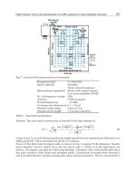
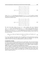
Three bearing types were considered, as illustrated in figure 1. Bearing type 1 featured four
supply ports situated in the centre plane of the bearing; bearing type 2 featured two sets of
supply ports, situated at z=L/4 and z=3L/4; bearing type 3 also featured a central vented
circumferential chamber.
The three bearing types were comparable in terms of stiffness and damping coefficients, air
consumption and stability. In (Colombo et al., 2009) the authors compared bearing types 1
and 2 (see figure 1) considering the same supply port diameter d
s
. The bearing with double
array entries (bearing type 2) was found to be 30% stiffer than the one with a single central
array (bearing type 1) but the air consumption was two times as much. Moreover, bearing 2
was more stable: the rotor mass at incipient whirl instability was about 50% greater.
Another point of interest was which bearing type was to be preferred for the same level of
air consumption. In this paper the bearings illustrated in figure 1 were compared
considering different supply port diameters in order to have the same air consumption.
3. Lubrication analysis
3.1 Mathematical model
The two-degree-of-freedom rotor equations of motion are shown in (1). The rotor mass is m.
As the shaft was assumed to have cylindrical motion, gyroscopic effects and tilting inertia
moments are non-existent. The second member of the equations is zero because the rotor
was assumed to be perfectly balanced and there were no external forces applied to it. This
was the most unstable condition, as shown in (Belforte et al., 1999).
()
()
2
00
2
00
2,cos 0
2,sin 0
L
L
mx p z rd dz
my p z rd dz
π
π
θθθ
θθθ
⎧
+
=
⎪
⎪
⎨
⎪
+
=
⎪
⎩
∫∫
∫∫
(1)
Comparison between Different Supply Port Configurations in Gas Journal Bearings
479
Fig. 1. Bearing types under study
The pressure distribution in clearance h was calculated solving the distributed parameters
problem described by the Reynolds equation for a compressible-fluid-film journal bearing
(2), assuming isothermal gas expansion.
(
)
(
)
3300
12 6 12
p
hph
pp
G
ph ph R T
z z r r rdrd t
μμωμ
θθ θ θ
∂∂
∂∂
∂∂
⎛⎞⎛ ⎞
++ =+
⎜⎟⎜ ⎟
∂∂∂ ∂ ∂ ∂
⎝⎠⎝ ⎠
(2)
Mass flow rate G at supply orifice was calculated in accordance with the isentropic
expansion formula (3), corrected by experimentally identified discharge coefficient c
d
,
expressed by eq. (4). Reynolds number at the supply hole was calculated as per equation (5).
Formula (4) is the result of an extensive set of experimental tests carried out on air pads with
different inherence parameters (Belforte et al., 2008).
21
2
2
41
k
kk
cc c
s
ds
ss s
pp p
d
k
Gc p if b
kp p RTp
π
+
⎡⎤
⎛⎞ ⎛⎞
⎢⎥
=
−≥
⎜⎟ ⎜⎟
⎢⎥
−
⎝⎠ ⎝⎠
⎢⎥
⎣⎦
2
2
1
00
22
if
411
k
c
s
ds
s
p
d
k
Gc p b
kk p
RT
π
−
⎛⎞
=
<
⎜⎟
++
⎝⎠
(3)
New Tribological Ways
480
()
8.2
0.001
0.85 1 1
s
h
d
Re
d
cee
−
−
⎛⎞
⎜⎟
=− −
⎜⎟
⎝⎠
(4)
4
s
G
Re
d
π
μ
= (5)
Assuming a cylindrical shaft motion, the clearance may be expressed by the following:
(
)
0
() 1 cos sin
xy
hz h
ε
θε θ
=− − (6)
3.2 Solution method
The Reynolds equation was discretized using a finite difference method along directions z
and θ for integration over the fluid film. A rectangular grid with equi-spaced nodes in both
directions was considered. The number of nodes in the axial (index i) and circumferential
(index j) directions were n and m respectively. Equation (2) may be written for each node as
follows:
(
)
(
)
(
)
(
)
()( )
2222
1, , , 1, , , , 1 , , , 1 , ,
1
,,
2
,, , ,1 ,1, , ,
1
00
,,
,,
224
24
24
i j ij ij i j ij ij ij ij ij ij ij ij
tt
ij ij
ij ij ij ij ij ij ij ij
tt
ij ij
t
ij ij
pabpabpcdpcd
hh
pa c p p e p g
t
pp
RT
Gh
rz t
μ
μ
μ
θ
+− +−
−
+−
+
+
+−+++−+
⎛⎞
−
⎜⎟
−++− −+ +
⎜⎟
Δ
⎝⎠
−
+=
Δ
ΔΔ
(7)
where,
32
,,
,,
2
,
32
,,
,,
22 2
,
,
,,
,
3
2
3
2
612
ij ij
ij ij
i
j
ij ij
ij ij
i
j
ij
ij ij
i
j
hh
h
ab
zz
z
hh
h
cd
rr
h
h
eg
θ
θθ
μω μω
θθ
∂
⎛⎞
==
⎜⎟
Δ∂
Δ
⎝⎠
∂
⎛⎞
==
⎜⎟
∂
ΔΔ
⎝⎠
∂
⎛⎞
==
⎜⎟
Δ∂
⎝⎠
At the supply port G
i,j
was calculated using equation (3), whereas elsewhere it was zero. The
boundary conditions imposed were:
•
p=p
a
at z=0 and z=L; for bearing type 3 p=p
a
also at z=L/2
•
periodic condition at θ=0 and θ=2π.
The Euler explicit method was used, so equation (7) becomes:
11
,, ,,1,11,1,,,
,,
, ,,,,,, ,
tt
tt ttttttt
ij ij ij ij ij i j i j ij ij
i
j
i
j
hh
pp tfppppphh
z
θ
+−
+−+−
⎡
⎤
∂∂
⎛⎞⎛⎞
=+Δ⋅
⎢
⎥
⎜⎟⎜⎟
∂∂
⎝⎠⎝⎠
⎢
⎥
⎣
⎦
(8)
The system of nxm equations (8) was solved together with equations (3) to (6) and rotor
equations of motion (1).
Comparison between Different Supply Port Configurations in Gas Journal Bearings
481
The solution procedure started with a set of input data (shaft diameter, radial clearance,
bearing axial length, position and diameter of supply orifices, shaft speed).
To calculate the static pressure distribution, h was maintained constant in time and the
system was solved with initial condition p
i,j
=p
a
for each node.
Pressure distribution was evaluated at each time step and the bearing forces acting on the
shaft were updated in equation (1). Thus, the rotor trajectory was determined starting with
the initial static pressure distribution and using the following set of initial conditions:
(
)
(
)
0
00
x
xh
ε
= ;
(
)
(
)
0
00
y
yh
ε
=
(
)
0
0(0)
x
xh
ε
=
;
(
)
0
0(0)
y
yh
ε
=
3.3 Mesh size and time step definition
Calculations were made with different mesh sizes and the results were compared for
optimum trade-off between computational time and accuracy of the solution.
The grids are detailed in table 1.
nxm Δz (mm) rΔθ (mm)
13x24 4.17 6.54
17x32 3.12 4.91
25x48 2.08 3.27
49x96 1.04 1.64
Table 1. Mesh sizes used in calculations; r=25 mm, L/D=1
Figure 2 shows the axial and circumferential pressure distributions obtained for bearing
type 1 with different numbers of grid points. If the number of grid points is increased, the
pressure distribution becomes more clearly defined, but the difference is almost negligible.
Only at the supply ports, where pressure gradients are high, the difference is more marked.
The grid selected for calculation was n=49, m=96.
0 20 40 60
1
1.2
1.4
1.6
1.8
x 10
5
z axis [mm]
p [Pa]
bearing 1
13x24
17x32
25x48
49x96
0 30 60 90
1.2
1.3
1.4
1.5
1.6
1.7
1.8
x 10
5
circumferential axis [deg]
p [Pa]
bearing 1
13x24
17x32
25x48
49x96
Fig. 2. Axial and circumferential pressure distributions for bearing type 1 obtained with
different mesh grids; h
0
=20 μm, p
s
=5·10
5
Pa rel., d
s
=0.1 mm,
ω
=60 krpm,
ε
=0
New Tribological Ways
482
Euler explicit method was used to solve the time progression of the system. The rotor
trajectories obtained with different time steps Δt are compared in figure 3.
The rotor initial conditions were:
(
)
(
)
00; 00
xy
εε
=
=
(
)
(
)
00; 00
xy
εε
=
=
The trajectories are increasingly adjacent with decreasing Δt. The time step used in the paper
was Δt=10
-7
s.
-0.06 -0.04 -0.02 0 0.02 0.04 0.06 0.08
-0.08
-0.06
-0.04
-0.02
0
0.02
0.04
0.06
ε
x
ε
y
n=25; m=48
dt=4e-7
dt=2e-7
dt=1e-7
dt=5e-8
Fig. 3. Rotor trajectories with bearing type 1 obtained with different time steps and grid
25x48; initial conditions specified by
ε
x
(0)=0.05,
ε
y
(0)=0,
(
)
(
)
00, 00
xy
εε
=
=
, h
0
=20 μm,
p
s
=5·10
5
Pa rel., d
s
=0.1 mm,
ω
=60 krpm
4. Discussion and results
4.1 Resistance analysis
The air supply system may be described with an equivalent lumped parameters system,
illustrated in figure 4.
Orifice restriction resistance R
s
is related to the supply ports and decreases with increasing
diameter d
s
. It may be calculated using linearizing expression (3) with respect to
downstream pressure p
c
. Clearance resistance R
h
depends on clearance h
0
, on bearing
dimensions size and on the arrangement of the supply ports. It is obtained by solving the
distributed parameters problem and calculating pressure distribution in the clearance.
Imposing mass continuity in the lumped parameters system of figure 4, supply port
downstream pressure p
c
can be obtained by
()
s
cs sa
sh
R
pp pp
RR
=− −
+
(9)
Comparison between Different Supply Port Configurations in Gas Journal Bearings
483
This pressure depends both on the supply system and on clearance: at reduced d
s,
supply
port downstream pressure p
c
approximates ambient pressure p
a
, whereas with increased d
s
it
approaches supply pressure p
s
.
Analysis of resistances at different supply pressures with the shaft rotating in central
position was performed for bearings 1 and 2 in (Colombo et al., 2009) which shows the
relationship between supply port diameter d
s
and downstream pressure p
c
, confirming that
the influence of bearing number
Λ
on p
c
with rotor in centred position is almost negligible,
and air consumption is almost independent of speed.
Fig. 4. Lumped parameters model of the restriction and clearance resistances
4.2 Air consumption
The three bearings of figure 1 were compared in terms of air consumption, as shown in
figure 5. The air mass flow was calculated as a function of the clearance for different supply
port diameters. At reduced d
s
, the air consumption for bearing types 2 and 3 was quite
identical. Only for d
s
=0.2 mm a difference was noted at reduced clearance. The air flow in
different bearings (for different resistance R
h
) was found to be the same for supply orifices
in critical conditions, when air flow is only a function of p
s
.
As air consumption is a function of d
s
and h
0
, the supply ports diameter is determined at
specific rates of air consumption G, as shown in table 2.
Bearing type 1 was not considered for the last two values of G because the volume of air
passing through its orifices when p
c
=p
s
(in this condition R
s
=0) was lower than these values.
5 10 15 20 25 30 35
0
1
x 10
-4
clearance [
μ
m]
mass air flow [kg/s]
type 1; d
s
=0.05 mm
type 1; d
s
=0.1 mm
type 1; d
s
=0.2 mm
type 2; d
s
=0.05 mm
type 2; d
s
=0.1 mm
type 2; d
s
=0.2 mm
type 3; d
s
=0.05 mm
type 3; d
s
=0.1 mm
type 3; d
s
=0.2 mm
Fig. 5. Air consumption of the three bearings vs. air clearance for different supply port
diameters; calculations are for
Λ
=0 and with rotor in central position; p
s
=5·10
5
Pa rel.
New Tribological Ways
484
bearing type
diameter d
s
[mm] air flow G·10
4
[kg/s]
1 0.155
2 0.1
3 0.1
0.5
1 0.383
2 0.2
3 0.2
1.42
1 0.8
2 0.282
3 0.275
2.14
2 0.4
3 0.372
2.94
2 0.6
3 0.8
4.28
Table 2. Supply port diameter d
s
considered in calculations for the three bearings at different
air consumption G; p
s
=5·10
5
Pa rel.
4.3 Pressure distribution
Figures 6 and 7 compare the axial and circumferential pressure distributions in the three
bearings with rotor in central position and restriction parameters specified in table 2. Bearing
type 1 shows a lower ratio R
s
/R
h
than the other bearings because its maximum pressure is the
highest. At G=0.5·10
-4
kg/s all bearings have orifices in sonic conditions, being p
c
/p
s
<b. At
G=2.14·10
-4
kg/s bearing type 1 is near saturation condition (p
c
p
s
). Speed stretches the
circumferential pressure profile toward the direction of rotation, as visible in figure 7.
4.4 Bearing stiffness
Bearing stiffness was calculated by imposing a shaft displacement of 1 μm along direction x
and evaluating the bearing reaction force.
Bearing stiffness k was
22
xx x
y
kkk=+ (10)
where the stiffness coefficients calculated in steady-state conditions were
()
2
00
00
,cos
L
x
xx
xx
p
zrddz
F
k
hh
π
θ
θθ
εε
==
∫∫
()
2
00
00
,sin
L
y
xy
xx
p
zrddz
F
k
hh
π
θ
θθ
εε
==
∫∫
Non-dimensional stiffness k*, given by
*
0
a
h
kk
p
LD
= (11)
Comparison between Different Supply Port Configurations in Gas Journal Bearings
485
0 10 20 30 40 50
1
1.2
1.4
1.6
1.8
2
2.2
2.4
x 10
5
G=0.5e-4 kg/s,
ω
=0
z axis [mm]
p [Pa]
bearing 1
bearing 2
bearing 3
0 10 20 30 40 50
1
1.2
1.4
1.6
1.8
2
2.2
x 10
5
G=0.5e-4 kg/s,
ω
=200 krpm
z axis [mm]
p [Pa]
bearing 1
bearing 2
bearing 3
0 10 20 30 40 50
1
1.5
2
2.5
3
3.5
4
x 10
5
G=1.42e-4 kg/s,
ω
=0
z axis [mm]
p [Pa]
bearing 1
bearing 2
bearing 3
0 10 20 30 40 50
1
1.5
2
2.5
3
3.5
4
x 10
5
G=1.42e-4 kg/s,
ω
=200 krpm
z axis [mm]
p [Pa]
bearing 1
bearing 2
bearing 3
0 10 20 30 40 50
1
2
3
4
5
x 10
5
G=2.14e-4 kg/s,
ω
=0
z axis [mm]
p [Pa]
bearing 1
bearing 2
bearing 3
0 10 20 30 40 50
1
1.5
2
2.5
3
3.5
4
4.5
x 10
5
G=2.14e-4 kg/s,
ω
=200 krpm
z axis [mm]
p [Pa]
bearing 1
bearing 2
bearing 3
New Tribological Ways
486
0 10 20 30 40 50
1
1.5
2
2.5
3
3.5
4
x 10
5
G=2.94e-4 kg/s,
ω
=0
z axis [mm]
p [Pa]
bearing 2
bearing 3
0 10 20 30 40 50
1
1.5
2
2.5
3
3.5
4
x 10
5
G=2.94e-4 kg/s,
ω
=200 krpm
z axis [mm]
p [Pa]
bearing 2
bearing 3
0 10 20 30 40 50
1
1.5
2
2.5
3
3.5
4
4.5
x 10
5
G=4.28e-4 kg/s,
ω
=0
z axis [mm]
p [Pa]
bearing 2
bearing 3
0 10 20 30 40 50
1
1.5
2
2.5
3
3.5
4
4.5
x 10
5
G=4.28e-4 kg/s,
ω
=200 krpm
z axis [mm]
p [Pa]
bearing 2
bearing 3
Fig. 6. Axial pressure distribution in the three bearings with
ω
=0 and
ω
=200 krpm for five
different air consumption rates; restriction parameters are specified in table 2, h
0
=20 μm,
p
s
=5·10
5
Pa rel.,
ε
=0
0 90 180 270 360
1
1.2
1.4
1.6
1.8
2
2.2
2.4
x 10
5
G=0.5e-4 kg/s,
ω
=0
circumferential axis [deg]
p [Pa]
bearing 1
bearing 2
bearing 3
0 90 180 270 360
1
1.2
1.4
1.6
1.8
2
2.2
x 10
5
G=0.5e-4 kg/s,
ω
=200 krpm
circumferential axis [deg]
p [Pa]
bearing 1
bearing 2
bearing 3
Fig. 7. Axial pressure distribution in bearing type 1 with
ω
=0 and
ω
=200 krpm for G=0.5·10
-4
kg/s; h
0
=20 μm, p
s
=5·10
5
Pa rel.,
ε
=0
Comparison between Different Supply Port Configurations in Gas Journal Bearings
487
is shown in figure 9 vs.
Λ
for the three bearings, considering different restriction parameters.
Figure 9 also shows steady-state attitude angle
β
, calculated as follows:
1
tan
x
y
xx
k
k
β
−
=
(12)
Fig. 8. Bearing reaction force on the journal in steady-state conditions due to shaft
displacement along direction x
Stiffness increased with
Λ
up to saturation (
Λ
>100). At G=0.5·10
-4
kg/s bearing type 1 was
found to be stiffer than the other two, regardless of
Λ
, but at higher air consumption bearing
type 2 exhibited greater stiffness at low speeds (
Λ
<9).
With the three bearings in sonic conditions (G=0.5·10
-4
kg/s) stiffness trends do not intersect
and their difference was almost constant. When bearing type 1 approached saturation
(p
c
p
s
), its stiffness at low speed dropped (see case with G=1.42·10
-4
kg/s). This happened
also for bearing type 2, but at greater air consumptions. Stiffness at high speeds (
Λ
>100)
always increased with G. At G=4.28·10
-4
kg/s, stiffness at low speeds for bearing types 2 and
3 coincided at very low values, due to saturation of bearings.
The attitude angle, with increasing
Λ,
also increased from zero to a maximum and then
returned to zero. The extent of maximum depended on the difference between bearing
stiffness at low and high speeds: where this difference was high, also maximum
β
was high.
Table 3 shows ratio k*(
Λ
>100)/k*(
Λ
=0) for the three bearings to highlight this relationship.
4.5 Rotor trajectories
The whirl motion of the perfectly balanced rotor during rotation is represented in figure 10.
The motion can be stable or unstable. In the former case the rotor is attracted toward the
centre of the bushing after initial disturbance; in the latter case the bearing forces move the
rotor away from central position.
New Tribological Ways
488
bearing type
k*(
Λ
>100)/k*(
Λ
=0)
air flow G·10
4
[kg/s]
1 2.62
2 2.71
3 3.75
0.5
1 2.54
2 1.82
3 2.4
1.42
1 5.8
2 2
3 2.2
2.14
2 2.5
3 2.26
2.94
2 5.33
3 3.08
4.28
Table 3. Ratio k*(
Λ
>100)/k*(
Λ
=0) for the three bearings given different air consumptions G
10
-1
10
0
10
1
10
2
0
0.5
1
1.5
2
2.5
G=0.5e-4 kg/s
Λ
k*
bearing 1
bearing 2
bearing 3
10
-1
10
0
10
1
10
2
-40
-30
-20
-10
0
G=0.5e-4 kg/s
Λ
β
[deg]
bearing 1
bearing 2
bearing 3
10
-1
10
0
10
1
10
2
0.5
1
1.5
2
2.5
3
G=1.42e-4 kg/s
Λ
k*
bearing 1
bearing 2
bearing 3
10
-1
10
0
10
1
10
2
-25
-20
-15
-10
-5
0
G=1.42e-4 kg/s
Λ
β
[deg]
bearing 1
bearing 2
bearing 3
Comparison between Different Supply Port Configurations in Gas Journal Bearings
489
10
-1
10
0
10
1
10
2
0.5
1
1.5
2
2.5
3
3.5
4
G=2.14e-4 kg/s
Λ
k*
bearing 1
bearing 2
bearing 3
10
-1
10
0
10
1
10
2
-50
-40
-30
-20
-10
0
G=2.14e-4 kg/s
Λ
β
[deg]
bearing 1
bearing 2
bearing 3
10
-1
10
0
10
1
10
2
0.5
1
1.5
2
2.5
3
3.5
G=2.94e-4 kg/s
Λ
k*
bearing 2
bearing 3
10
-1
10
0
10
1
10
2
-25
-20
-15
-10
-5
0
G=2.94e-4 kg/s
Λ
β
[deg]
bearing 2
bearing 3
10
-1
10
0
10
1
10
2
0
1
2
3
4
5
G=4.28e-4 kg/s
Λ
k*
bearing 2
bearing 3
10
-1
10
0
10
1
10
2
-40
-30
-20
-10
0
G=4.28e-4 kg/s
Λ
β
[deg]
bearing 2
bearing 3
Fig. 9. Non-dimensional bearing stiffness k* and attitude angle
β
vs. bearing number
Λ
for
the three bearings
New Tribological Ways
490
The initial condition used in the following curves are specified by
(
)
(
)
00.05; 00
xy
εε
=
=
() () ()
00; 00
xx
k
xyx
m
==
Initial tangential speed was imposed on the rotor to produce a centrifugal force equal to the
static radial force. This particular condition was adopted to decrease the simulation time
required to distinguish stability from instability. In fact, with a different initial condition on
y
, the trajectory would have been less circular, necessitating simulation of a longer
transient. Stability decreased with increasing rotor mass m: figure 10 shows a comparison of
rotor trajectories obtained for the same initial condition but at different values of m. The
rotor-bearing system became unstable when the dynamic attitude angle turned negative, as
shown in figure 11. In the stable condition the rotor angular moment, calculated relative to
the centre of the bushing, decreased with time. In unstable conditions, the mechanical work
done by bearing forces was found to be positive and the rotor angular moment increased
(see figure 11b). The curves in figure 11 help distinguish stable versus unstable conditions,
as resulting when compared to figure 10.
-2 -1 0 1 2
x 10
-6
-2
-1.5
-1
-0.5
0
0.5
1
1.5
2
x 10
-6
xg [m]
yg [m]
m=9 kg
m=9.5 kg
m=11 kg
Fig. 10. Rotor trajectories with different rotor masses and initial condition x(0)=1 μm,
dy/dt(0)=x(0)·(k
xx
/m)^(0.5);
ω
=20 krpm, bearing type 1
Comparison between Different Supply Port Configurations in Gas Journal Bearings
491
0 0.005 0.01 0.015 0.02
-25
-20
-15
-10
-5
0
5
10
t [s]
attitude angle
β
[deg]
m=9 kg
m=9.5 kg
m=11 kg
0 0.005 0.01 0.015 0.02
0.5
1
1.5
2
2.5
3
x 10
-8
t [s]
angular moment [kg*m
2
/s]
m=9 kg
m=9.5 kg
m=11 kg
(a) (b)
Fig. 11. Attitude angle vs. time (a) and rotor angular moment vs. time (b) with different
rotor masses and initial condition x(0)=1 μm, dy/dt(0)=x(0)·(k
xx
/m)^(0.5);
ω
=20 krpm,
bearing type 1
The three bearings are compared in figures 12 and 13, showing the rotor trajectories for
identical initial condition, the attitude angle vs. time and the rotor angular moment vs. time.
In this case bearing types 1 and 2 are very similar, while bearing type 3 is unstable.
-3 -2 -1 0 1 2 3 4
-3
-2
-1
0
1
2
3
xg [
μ
m]
yg [
μ
m]
bearing 1
bearing 2
bearing 3
Fig. 12. Rotor trajectories with the three bearing types; m=1 kg,
ω
=50 krpm; initial conditions
x(0)=1 μm and dy/dt(0)=x(0)·(k
xx
/m)^(0.5).
New Tribological Ways
492
0 2 4 6
x 10
-3
-40
-20
0
20
40
60
80
t [s]
attitude angle [deg]
bearing 1
bearing 2
bearing 3
1 2 3 4 5
x 10
-3
0
0.5
1
1.5
2
2.5
x 10
-8
t [s]
angular moment [kg*m
2
/s]
bearing 1
bearing 2
bearing 3
(a) (b)
Fig. 13. Attitude angle vs. time a) and rotor angular moment vs. time b) for the three bearing
types; m=1 kg,
ω
=50 krpm; initial conditions x(0)=1 μm and dy/dt(0)=x(0)·(k
xx
/m)^(0.5).
4.6 Bearing damping factor
Stiffness and damping coefficients of gas bearings are known to depend on bearing number
Λ
and also on whirl frequency
ν
. Stability may also be evaluated through the equivalent
damping factor calculated by identifying the system with a second-order differential
equation having constant coefficients:
0mx cx kx
+
+=
(13)
The damping factor is expressed by
2
c
km
ζ
= (14)
and the radial coordinate of the journal centre is
(
)
0
n
t
rr e
ζ
ω
−
=
(15)
where the natural frequency is
n
k
m
ω
= (16)
The journal motion is stable when described by a spiral which decreases with time. In this
case
ζ
is positive. When the damping factor is negative the spiral increases with time.
Figure 14 shows damping factor
ζ
vs. m for G=0.5·10
-4
kg/s. In this case bearing type 3
exhibited lower damping capacity than the other bearings.
4.7 Whirl ratio
The shaft whirl frequency vs. m is shown in figure 15 for G=0.5·10
-4
kg/s. The whirl
frequency decreases with m and increases with
ω
. The rotor mass at stability threshold is
Comparison between Different Supply Port Configurations in Gas Journal Bearings
493
10
-1
10
0
10
1
10
2
-0.15
-0.1
-0.05
0
0.05
0.1
0.15
0.2
m [kg]
ζ
bearing 1; 20 krpm
bearing 1; 50 krpm
bearing 1; 100 krpm
bearing 1; 200 krpm
bearing 2; 20 krpm
bearing 2; 50 krpm
bearing 2; 100 krpm
bearing 2; 200 krpm
bearing 3; 20 krpm
bearing 3; 50 krpm
bearing 3; 100 krpm
bearing 3; 200 krpm
Fig. 14. Damping factor vs. rotor mass at different rotating speeds; G=0.5·10
-4
kg/s
10
-1
10
0
10
1
10
4
10
5
m [kg]
ν
[rpm]
bearing 1; 20 krpm
bearing 1; 50 krpm
bearing 1; 100 krpm
bearing 1; 200 krpm
bearing 2; 20 krpm
bearing 2; 50 krpm
bearing 2; 100 krpm
bearing 2; 200 krpm
bearing 3; 20 krpm
bearing 3; 50 krpm
bearing 3; 100 krpm
bearing 3; 200 krpm
Fig. 15. Whirl frequency
ν
vs. m at different rotating speeds; G=0.5·10
-4
kg/s
New Tribological Ways
494
0.5 1 1.5 2
0.4
0.45
0.5
0.55
m/m
th
γ
20 krpm
50 krpm
100 krpm
200 krpm
Fig. 16. Whirl ratio
γ
vs. m/m
th
at different speeds; bearing type 1, G=0.5·10
-4
kg/s
indicated as m
th
. Figure 16 shows whirl ratio
γ
vs. ratio m/m
th
. At the stability threshold it is
slightly lower than 0.5 and decreases with shaft mass m.
4.8 Stability threshold
Figure 17 shows rotor mass m vs bearing number
Λ
at the stability threshold for the three
bearings. On logarithmic axes the curves are linear and may be expressed by
(
)
10 10 0 10 10 0
log log log logmm
α
−
=Λ−Λ (17)
where m
0
and
Λ
0
refer to a reference condition. Angular coefficient α is -2 approx. From this
equation we obtain the following relation:
00
m
m
α
⎛⎞
Λ
=
⎜⎟
Λ
⎝⎠
(18)
The stability thresholds with different inherence parameters were found to be similar, but
translated to different mass values.
4.9 Comparison of bearing types at different restriction parameters
Figure 18 shows the trends of bearing stiffness vs. G for
ω
=0 rpm and
ω
=200 krpm, and
figure 19 shows critical journal mass m
th
vs. G. The order of preference of the bearings
changes when different air consumption rates are considered.
If stiffness at low bearing numbers is the most important parameter, bearing type 1 is the
best option only for G≤0.5·10
4
kg/s, in other cases bearing type 2 is to be preferred. If it is
important to maximize the bearing stiffness at high bearing numbers bearing type is to be
chosen.
Considering the stability threshold, bearing type 2 is the best one for G>0.5·10
4
kg/s, while
for G≤0.5·10
4
kg/s bearing 1 is to be preferred.
Comparison between Different Supply Port Configurations in Gas Journal Bearings
495
10
1
10
-2
10
-1
10
0
10
1
10
2
Λ
m
th
[kg]
bearing 1, G=0.5e-4 kg/s
bearing 2, G=0.5e-4 kg/s
bearing 3, G=0.5e-4 kg/s
bearing 1, G=1.42e-4 kg/s
bearing 2, G=1.42e-4 kg/s
bearing 3, G=1.42e-4 kg/s
Fig. 17. Rotor mass m at stability threshold vs. bearing number
Λ
for the three bearings
0 2 4 6
x 10
-4
0.2
0.4
0.6
0.8
1
1.2
1.4
1.6
ω
=0 krpm
air consumption [kg/s]
k*
bearing 1
bearing 2
bearing 3
0 2 4 6
x 10
-4
1
1.5
2
2.5
3
3.5
4
ω
=200 krpm
air consumption [kg/s]
k*
bearing 1
bearing 2
bearing 3
a) b)
Fig. 18. Bearing stiffness k* vs. air consumption for the three bearings; a)
ω
=0 rpm, b)
ω
=200 krpm
New Tribological Ways
496
0.5 1 1.5 2 2.5 3 3.5 4 4.5
x 10
-4
0.04
0.06
0.08
0.1
0.12
0.14
0.16
0.18
0.2
0.22
0.24
air consumption [kg/s]
m
th
bearing 1
bearing 2
bearing 3
Fig. 19. Rotor mass at stability threshold vs. air consumption for the three bearings
5. Conclusion
Three bearing types were compared for different restriction parameters.
Bearing type 1 featured four supply ports situated in the bearing centre plane. Bearing type
2 featured two sets of supply ports, situated at z=L/4 and z=3L/4. Bearing type 3 also
featured a central vented circumferential chamber.
The following conclusions were drawn:
•
bearing type 2 in general is to be preferred to the other bearing types because of the
higher stiffness and stability threshold at equal air consumption;
•
with increasing
Λ,
the attitude angle went from zero to max. subsequently returning to
zero; max. value was proportional to the difference between bearing stiffness at low and
at high speeds;
•
at the stability threshold the whirl ratio was slightly lower than 0.5;
•
the curve of m
th
vs.
Λ
on the logarithmic axes was linear and with changing restriction
parameters the shaft critical mass changed by a factor regardless of speed.
6. List of symbols
D bearing diameter
F bearing force on journal
G air mass flow rate
L bearing axial length
R
s
pneumatic resistance of the supply hole
R
h
pneumatic resistance of clearance
R
0
gas constant, in calculations R
0
=287.6 m
2
/s
2
K
Re Reynolds number
T
0
absolute temperature, in calculations T
0
=288 K
Comparison between Different Supply Port Configurations in Gas Journal Bearings
497
b ratio of critical pressure to admission pressure, b=0.528
c damping coefficient
c
d
supply hole discharge coefficient
h local air clearance
h
0
clearance with rotor in centred position
k bearing radial stiffness
k* non-dimensional bearing radial stiffness
m rotor mass
m
th
rotor mass at stability threshold
n,m number of nodes along axial and circumferential directions
x,y,z cartesian coordinates
p
a
ambient pressure
p
c
supply hole downstream pressure
p
s
bearing supply pressure
r,
θ
,z cylindrical coordinates
t time
Λ
bearing number,
Λ
=6m
ω
/p
a
·(D/2h
0
)
2
β
steady attitude angle
γ
whirl ratio,
γ
=
ν/ω
ε
eccentricity ratio
μ
dynamic viscosity, in calculations
μ
=17.89·10
-6
Pa·s
ν
whirl frequency
ζ
bearing damping factor
ω
rotor angular speed
7. References
Andres, L.S. (1990). Approximate analysis of turbulent hybrid bearings, static and dynamic
performance for centered operation. ASME Journal of Tribology, Vol. 112, 692-698.
Belforte, G.; Raparelli, T.; Viktorov, V. (1999). Theoretical investigation of fluid inertia effects
and stability of self-acting gas journal bearings. ASME Journal of Tribology, Vol. 121,
836-843.
Belforte, G.; Raparelli, T.; Viktorov, V.; Trivella, A. (2008). Discharge coefficients of orifice-
type restrictor for aerostatic bearings, Tribology International, Vol. 40, 512-521.
Cheng, H.S.; Pan, C.H.T. (1965). Stability analysis of gas-lubricated, self-acting, plain,
cylindrical, journal bearings of finite length, using Galerkin’s method. ASME
Journal of Basic Engineering, 185-192.
Colombo, F.; Raparelli, T.; Viktorov, V. (2009). Externally pressurized gas bearings: a
comparison between two supply holes configurations. Tribology International, Vol.
42, 303-310.
Gross, W.A.; Zachmanaglou, E.C. (1961). Perturbation solutions for Gas lubricating films.
Trans ASME, Journal of Basic Engineering, Vol. 83, 139-144.
Han, D.C.; Park, S.S.; Kim, W.J.; KimJ.W. (1994). A study on the characteristics of externally
pressurized gas bearings. Precision Engineering, Vol. 16, No. 3, 164-173.
Heller, S.; Shapiro, W.; Decker, O. (1971). A porous hydrostatic gas bearing for use in
miniature turbomachinery. ASLE Transactions, 144-155.