Progress in Biomass and Bioenergy Production Part 15 docx
Bạn đang xem bản rút gọn của tài liệu. Xem và tải ngay bản đầy đủ của tài liệu tại đây (2.11 MB, 30 trang )
21
Microbial Conversion of
Biomass: A Review of Microbial Fuel Cells
Cagil Ozansoy and Ruby Heard
School of Engineering and Science, Victoria University
Melbourne, Victoria,
Australia
1. Introduction
The cleaner generation of energy is a vital concept if we are to ensure the survival of our
current lifestyle past the depletion of the Earth’s fossil fuel supply. The study described in
this chapter investigates the alternative energy producing method of microbial conversion
of biomass to produce electrical energy. Currently techniques are being explored to
minimise the cost of building and running cells in which microbial conversion takes place.
There are several areas where improvements may be made including the physical design of
the cell, the catalyst used in the cathode chamber, the membrane material and the ideal low-
cost substrate. The study presented in this chapter provides a review of Microbial Fuel Cells
(MFCs), and discusses the design and construction of MFCs and presents the results of tests
carried out with a number of constructed cells.
There is no doubt that the world’s increasing population is rapidly depleting planet’s finite
energy resources. It is common knowledge today that the techniques developed to produce
electricity and run our vehicles have also been leading to temperature rises resulting in
climate changes all over the world. Currently, the world consumes approximately 13
Terawatts of power (Chae et al., 2009) every year while a mere 20 % of this is produced from
renewable sources (Hopwood & Cohen, 2000). Techniques of harnessing energy from
renewable sources are continuously being further developed all over the world, but are still
yet to reach the efficiency levels, which would make these techniques comparable to the
traditional, yet unsustainable coal-fired generation.
The discovery of a process in which bacteria are utilised in the fermentation of organic
substrates to produce electricity can assist with the transition towards more sustainable
ways of energy generation. This is the concept of a Microbial Fuel Cell (MFC). Later, it was
also discovered that a variation of the MFC design could produce hydrogen instead through
electrolysis. This was termed a Microbial Electrolysis Cell (MEC) (Logan, 2008).
Hydrogen is the most abundant element in the universe with more than 9 out of every 10
atoms being hydrogen atoms. Our most precious resource is made mainly of hydrogen. The
Sun’s gravitational force pulls hydrogen atoms together which releases helium and energy
by the process of fusion. This energy is received on earth as the light and heat which
sustains life on Earth. Hydrogen is recognised as an attractive energy carrier due to its clean,
efficient and renewable nature (Chae et al., 2009) . It has applications in the production of
Progress in Biomass and Bioenergy Production
410
ammonia and methanol, the refining of metals and most recently as a clean fuel for
powering vehicles. Hydrogen can be produced in a number of ways including as a by-
product during the cracking of crude oil or by way of electrolysis in a diaphragm cell
(Knapp, 2002). The majority of hydrogen gas produced today is developed from fossil fuels
contributing to the release of carbon dioxide (Logan et al., 2008). An MEC improves on
traditional hydrogen production technology by producing hydrogen yields many times
greater than fermentation and at greater energy efficiencies than water electrolysis (Call &
Logan, 2008; Logan et al., 2008).
Both MFCs and MECs have great potential in the renewable energy trend. As such many
researchers across the world are investigating improvements to the two different systems.
While the physical cell structures which can be used are the same, it is the reactions inside
the cell which differ. In a microbial fuel cell, bacteria attached to the anode oxidise organic
material releasing carbon dioxide and protons into the anode chamber solution. Electrons
are transferred to the anode itself which then flow through an electrical circuit to the
cathode where they are consumed in the reduction of oxygen. Meanwhile protons cross into
the cathode chamber via a membrane. A current is therefore produced as there is a flow of
electrons. However, in the absence of oxygen in the cathode chamber no current will be
produced. This leads to the variations which constitute an electrolysis cell. With the addition
of a small voltage between the anode and cathode, protons now become reduced at the
cathode and hydrogen gas is produced (Logan et al., 2006; Call & Logan, 2008; Logan &
Cheng, 2008). This process is known as electrohydrogenesis (Logan et al., 2008).
In an attempt to increase the power and hydrogen produced by MFCs and MECs
respectively, researchers have recognized a number of areas where variations in design can
be studied. Numerous papers have been published as to the effects of differing pH,
temperature, electron acceptor, electrode surface area, reactor size and electrode and
membrane material (Logan et al., 2008). Many carbon and graphite electrode materials from
carbon paper to graphite pencil leads have been trialled with the common conception that
graphite brushes produce the best results due to their large surface area (Logan, 2008).
Reactor designs are limited only by the imagination and many variations of the original two
bottle design have emerged including single chamber, cube, cylinder and U-shaped reactors.
A review of MEC technology has identified several research areas that must still be
addressed before MECs can be considered a mature hydrogen production method. These
observations are:
• More experience is required with real organic feed stocks containing complex organic
substrates such as polymeric and particulate substances;
• Novel, more cost-effective chemical and/or biological cathodes need to be developed
that show low potential losses and are not platinum-based;
• Membrane pH gradients need to be eliminated, or membranes should not be used in
the reactor;
• Methanogenic consumption of the hydrogen product needs to be prevented (in the case
of membrane-less MECs and/or MECs with a biocathode); and, most critically,
• A cost-effective, scalable MEC design needs to be developed.
As mentioned above, often cathodes are platinum based (He & Angenent, 2006; Logan &
Cheng, 2008). The platinum acts as a catalyst and is necessary to enhance the rate of
reduction of oxygen at the cathode (Logan et al., 2008). As platinum is highly expensive and
can be poisoned by components of the substrate solution (Logan et al., 2008; You et al., 2009)
Microbial Conversion of Biomass: A Review of Microbial Fuel Cells
411
it is desirable to eliminate it from MFCs and MECs altogether. Several alternatives have
been investigated including chemical catholytes, biocathodes and transitional metals (He &
Angenent, 2006). Thus far the highest power ever achieved in an MFC has been using a
ferricyanide cathode (He & Angenent, 2006). In order to minimise costs and work towards
the eradication of platinum potassium permanganate has been used at the cathode.
2. Problem analysis
There are two significant energy related challenges facing the world. The first one is the
production of cleaner, renewable energy at high efficiencies and low costs, the other, the
consideration of efficient storage techniques for excess or intermittently produced electricity.
Although renewable forms of energy have no or little negative environmental impacts they
can have negative social, economical and technical problems associated with them. Wind
turbines for instance create cleaner and renewable energy but are extremely expensive to set
up and maintain. There are also social issues regarding their location as many people find
them to be noisy and unattractive. Hydropower is one of the cleanest forms of renewable
energy but it too is bound by locations problems. Hydropower requires suitable dam
locations and most importantly, large amounts of water, something that many countries
including Australia cannot provide. Solar power again is expensive and suffers low
efficiencies while also having environmental effects. Solar panels require large amounts of
energy to be produced and silicon production has recently led to unsafe toxic waste
disposal. A potential solution to many of these problems are the fuel cells. They are highly
efficient, reliable, are noiseless, emission-less and run on widely available fuels.
One problem with several forms of renewable energy is that it is produced intermittently,
that is power is only produced at certain times not continuously. Such generation techniques
include photovoltaic solar power and wind turbines as they both rely on the natural
phenomena of sunlight and wind respectively. For these technologies to be viable options to
replace less environmentally friendly generation methods the energy produced during
generation periods must be able to be stored for use when generation is not possible. For
example, solar power cannot be generated at night or in periods of low sunlight levels
however the energy produced on sunny days could be stored and then used at these times.
Many forms of energy storage exist including mechanical, chemical, thermal,
electrochemical, electrical and biological storage. Other forms of clean, renewable energy are
unaffected by environmental factors and can produce electricity constantly. These forms
include hydropower, geothermal and fuel cells to name a few.
As previously mentioned, some renewable energy generation techniques require the energy
to be stored for later use, in fact this is considered one of the biggest challenges affecting the
solar power industry (Zyga, 2009). Electric cars are also being held back by the lack of
appropriate storage techniques as batteries are heavy and inefficient when compared with
fuels like petrol and gasoline (HowStuffWorks.com, 2000). World energy consumption is
predicted to rise 44 percent over the next twenty years with green house gas emissions
increasing a staggering 39 percent (Finfacts-Team, 2009). Obviously, this will have
significant impact on climate change and put pressure on the power industry to cope with
the increasing demand. Already high demand puts strain on the industry, not to mention on
the customers wallets. Peak energy periods usually incur a higher cost to consumers.
The power grid also experiences problems of over-demand in extreme weather conditions
where the use of heaters/air conditioners is extremely high. This generally results in power
Progress in Biomass and Bioenergy Production
412
outages for long periods of time. In the United States 14 percent of the country’s power
plants and known as “peaking plants,” expensive gas turbines that are only operated during
rare hours of extremely high demand (Plumer, 2009). This is an instance of where efficient,
cost effective storage methods are highly desirable. The use of renewable generation
techniques is predicted to increase throughout the world to contribute to the populations
growing energy needs. Therefore, there will also be a greater need for energy storage to
facilitate the continuous use of energy from intermittent sources.
3. Possible solutions
This section presents a review of different types of fuel cells and a comparative analysis in
terms of design and construction difficulty, material expenses and potential efficiencies. The
two main cells chosen are Hydrogen and Microbial Fuel Cells. Viable options are considered
for all the necessary components including; a membrane, electrodes and a catalyst as well as
possibilities for reactor configurations and substrates.
Several solutions to designing a clean energy storage device have also been evaluated for
their suitability to store the electrical energy produced by the fuel cell. The energy can be
stored in many forms such as kinetic, chemical, electrochemical and electrical. These types
of energy storage have all been reviewed as candidates. The required solution must again
prove to be of reasonable expense and effort to design, build and implement.
3.1 Fuel cells
A fuel cell is a device that is capable of converting the chemical energy in a fuel and an
oxidant into electricity and a clean by product (FCTec, 2010). Fuels can consist of traditional
compounds like hydrogen, natural gas, methanol and gasoline while a common oxidant is
oxygen. A fuel cell is an electrochemical system like a battery however a fuel cell does not
run down or need recharging; as long as a fuel and oxidiser are present the cell will generate
electricity.
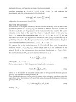
All fuel cells are constructed and operate in the same general manner. Figure 1 shows a cell
that consists of three materials sandwiched together, namely an anode, electrolyte and
cathode. The anode and cathode are known as electrodes and are made of some form of
conductive material. The anode and cathode are where the oxidation of the fuel and
reduction of the oxidant occur respectively. This is facilitated by a catalyst, which can
consist of a range of substances. When the fuel is oxidised, electrons and protons are
produced. The protons are able to flow through the electrolyte as it is a substance that
allows ion exchange while electrons are blocked. Electrons therefore pass through the anode
and to the cathode via an external circuit where they react with the protons and oxidant.
This results in a by-product (usually water), while the flow of electrons constitutes an
electrical current and therefore electricity generation.
Fuel cells are suitable for a wide range of applications. They are particularly useful as power
sources in remote locations such as spacecraft, remote weather stations, rural locations, and
even have military applications. Currently the use of fuel cells in cogeneration is a rapidly
growing area for office buildings and factories. The advantage of homes and businesses
using fuels cells is the savings on grid electricity and that excess energy produced can even
be sold back to the grid for profit. Future prospects for the technology includes powering
road and sea vehicles, providing off-grid power supplies and emergency power, micro fuel
cells to implement in small appliances and as portable charging docks.
Microbial Conversion of Biomass: A Review of Microbial Fuel Cells
413
Fig. 1. Basic configuration of a fuel cell (Ballard Power Systems)
3.1.1 Hydrogen fuel cell
The most common form of fuel cell is the hydrogen fuel cell. In this case hydrogen is the fuel
and oxygen is the oxidant. Pressurised hydrogen gas enters the anode chamber and is forced
through a catalyst (usually platinum) by the pressure. When hydrogen comes in contact
with the platinum it is split into two H+ ions and two electrons. Electrons conduct through
the anode and to the cathode via an external circuit. Meanwhile in the cathode chamber
oxygen gas is also forced into the catalyst where it splits into two strongly negatively
charged oxygen atoms. The strong negative oxygen atom charge attracts the positively
charged H+ ions through the membrane where they combine with the oxygen atoms and
the electrons to form a water molecule (Nice & Strickland, 2010).
Design’s can be as simple as using two pieces of platinum coated wire in a glass of water
(Field, 2008) however platinum is extremely expensive and the source of fuel also presents
difficulties. Water can be used as the source of hydrogen but there must be a way of splitting
the atoms to release the hydrogen and oxygen atoms. This process is known as electrolysis
and requires energy. Alternatively stored hydrogen and oxygen gas can be pumped into the
cell. Efficiencies achieved can be up to 80% (Nice & Strickland, 2010).
3.1.2 Microbial fuel cell
A microbial fuel cell utilises the electron extracting properties of special bacteria attached to
the anode to produce electricity. Bacteria attached to the anode oxidise organic material
releasing carbon dioxide and protons into the anode chamber solution. Electrons are
transferred to the anode itself which then flow through an electrical circuit to the cathode
where they are consumed in the reduction of oxygen. Meanwhile protons cross into the
cathode chamber via a membrane. A current is therefore produced as there is a flow of
electrons.
Progress in Biomass and Bioenergy Production
414
A range of alternatives are available for all components while a range of organic material
can be used as the cell’s fuel. One option is to use wastewater in the anode chamber. This
has the added benefit of water purification while electricity is produced. There is also no
need to deal with hard to store gases such as hydrogen which are also expensive to produce.
Organic matter can be sourced simply from household food scraps or garden waste. This
makes a microbial fuel cell easy and inexpensive to run. Alternative catalysts are available to
platinum which significantly reduces cell costs. Efficiencies achieved are comparable to
those achieved with hydrogen fuel cells.
3.2 MFC components
An MFC requires much the same components as any other fuel cell however there are some
drastic differences. Most obvious is the requirement for bacteria which is not an addition to
any other type of fuel cell. Where most other fuel cells incorporate chemicals to achieve their
electricity producing reactions, a microbial fuel cell requires a form of organic matter
(substrate) to maintain the bacteria also providing the means of generation. Reactions using
oxygen as the terminal electron acceptor are extremely slow so either a catalyst must be used
or a terminal electron acceptor with a faster reaction time must replace oxygen in the cathode
chamber. These alternatives for these things, along with the more conventional components;
membrane and electrodes as well as reactor configuration, are discussed below.
3.2.1 Reactor
Reactor configurations vary greatly from researcher to researcher. The size and shape of a
reactor is entirely up to the designer and as no stand out design has been identified the
variations continue with the goal of finding a scalable design. To date reactors have been
cube shaped, cylindrical, horse shoe shaped, two chamber and single chamber and H-type
configured and made of glass and various types of plastic, even buckets. Sizes also vary
widely with some reactors having volumes of a few square centimetres and others of up to a
square metre. So far researchers have speculated that single chamber reactors may show the
most promise but this has not deterred people from using two chamber types. In terms of
construction difficulties a single chamber reactor can be the harder of the two options. For
this reason the reactor for this research project will be a two chambered cell and to further
simplify the design and construction a cube shape will be used. Figure 2 depicts the
proposed cell design. The total reactor capacity will be 1.1L, 600mL in the anode chamber
and 500mL in the cathode chamber.
Fig. 2. Basic reactor design
Microbial Conversion of Biomass: A Review of Microbial Fuel Cells
415
3.2.2 Membrane
A membrane is described as a layer of material which serves as a selective barrier between
two mediums that is impermeable to specific particles, molecules or substances. Membranes
occur naturally in the bodies of plants and animals and are made artificially for separation
purposes in laboratories and industry. Synthetic membranes include anion exchange
membranes, cation exchange membranes and ultra filtration membranes. Studies have
shown that anion exchange membranes perform better than cation exchange membranes
due to a lower resistance (You et al., 2009) . These types of membranes are generally very
expensive, have high minimum orders or incur large freight charges as they are only
manufactured overseas. An alternative is membrane inclusive water resistant clothing such
as Gore-Tex. High quality ski clothing is specially made to contain a membrane within the
fabric to repel water. The fabric is suitable for fuel cell applications as it successfully
separates the liquids in the two chambers whilst allowing protons to flow from the anode to
the cathode chamber. Table 1 contains several membrane alternatives that would be suitable
for the microbial fuel cell.
Table 1. Membrane solutions
3.2.3 Electrodes
All fuel cells require two electrodes, an anode and a cathode. These electrodes facilitate the
transport of electrons through an external circuit hence resulting in electricity. Electrodes can
be made of any non corrosive, conductive material. Most commonly used materials include
carbon, graphite and steel. Steel has been found to be less effective for use in microbial fuel
cells as it is not a porous material and bacteria appear to be unable to attach themselves
(Logan, 2008) . Carbon and graphite are both widely available materials which come in many
forms. Carbon is available as paper, cloth and foam while graphite comes in the form of rods,
granules and brushes. Studies have not shown a distinct favourability towards neither carbon
nor graphite so we will assume that performance is very similar and depends more heavily on
electrode surface area. All above mentioned products are quite expensive and almost entirely
produced overseas so there is also a high freight cost involved. Several companies were found
to offer free samples of carbon foams and cloths however only one company does not charge a
shipping cost for the sample. For this reason vitreous reticulated carbon foam has been chosen
for the electrodes. Foam has an advantage over paper and cloth as it is more porous and has a
greater surface area to house more bacteria.
Progress in Biomass and Bioenergy Production
416
3.2.4 Substrate
A substrate is the substance contained in the anode chamber that is to be oxidised. As
mentioned earlier this can include fuels such as hydrogen and gasoline. In a microbial fuel
cell the substrate used can be any form of organic matter. Cells have been successfully
operated on chocolate (Markusic, 2010) , wine (Danigelis, 2009) , wastewater (Logan, 2008) ,
acetate (Liu et al., 2005; Sun et al., 2008), glucose (Logan, 2008) and more. Most frequently
glucose, wastewater and acetate are used in experiments with the highest results being
obtained with acetate (Logan, 2008) .
3.2.5 Catalyst/catholyte
The cathode chamber is where protons and electrons recombine and reduce an electron
acceptor. A common electrode acceptor is oxygen due to its abundance in air. When oxygen
is used however the reaction is very slow therefore the need for a catalyst arises. Most
MFC’s use platinum as the catalyst (Logan, 2008) however this is extremely expensive. Due
to the expense, which affects the viability of fuel cells, much research is aimed at finding an
equally efficient but less expensive catalyst. One option is to use a catholyte to replace
oxygen as the terminal electron acceptor. Chemicals such as ferricyanide and potassium
permanganate have been used successfully with results comparable to those achieved with
platinum (He & Angenent, 2006). These chemicals are far less expensive than platinum
however the disadvantage is that they are consumed in the reaction and must be replaced.
Research has also been conducted into the use of bacterial cathodes known as biocathodes.
The concept of a biocathode is that bacteria are attached to the cathode as they are to the
anode. Bacteria then assist the reduction of oxygen without the need for any additional
chemicals or substances (He & Angenent, 2006).
3.3 Common storage techniques
Energy storage is not a new development in fact people have been storing energy far before
the discovery of electricity. Energy storage can be achieved in many ways; some techniques
are simple such as those used in grandfather clocks while others involve complex chemical
reactions.
3.3.1 Mechanical (flywheel)
A flywheel is a form of mechanical storage that far predates any battery; in fact it is one of
humanities oldest and most familiar technologies. Examples are the potter’s wheel which
dates back six thousand years and more relevantly today the mechanism regulating the
strokes of pistons in a car engine. A flywheel is simply a wheel on an axle which is able to
store and regulate energy by continuously spinning. When spun at high speeds a fly wheel
becomes a bank for massive amounts of kinetic energy which can be drawn out when
required. Fly-wheel based batteries can reach energy densities 3-4 times higher than
traditional lead-acid cell batteries. Another advantage of flywheels is that they are able to
charge to full capacity in a matter of minutes rather than hours and discharge quickly
without damage. They are also unaffected by extreme temperatures and have an impressive
efficiency of 85-95% as well as a lifetime in decades (Putnam, 2007). A flywheel may not be
appropriate to store the energy produced by the fuel cell in this project due to safety
concerns associated with them caused by the high speed rotor. There is a possibility of the
rotor breaking loose and releasing energy is an uncontrolled fashion (Rayner, 2008). They
also experience a high current loss.
Microbial Conversion of Biomass: A Review of Microbial Fuel Cells
417
3.3.2 Electrochemical (battery)
A battery is a form of electrochemical energy storage, storing chemical energy and
converting it to electrical energy. Chemicals inside the battery produce electrons which cling
to the negative terminal. When the negative terminal is connected to the positive terminal
via a conductor, electrons flow from the negative terminal to the positive terminal releasing
their energy to a load. A battery is charged by doing the reverse of this action and applying
an electrical current to the terminals. The disadvantage of batteries is that they are expensive
and also heavy. This causes a significant problem for electric vehicles as weight is an
important limiting factor in vehicle speed. One application of fuel cells is as an alternative to
gasoline. For this reason batteries are not a suitable option for the storage of power from the
fuel cell in this project.
3.3.3 Chemical (hydrogen)
Hydrogen is the most copious element in the universe with more than 9 out of every 10 atoms
being hydrogen atoms. In fact our most precious resource is made mainly of hydrogen. The
Sun’s gravitational force pulls hydrogen atoms together which releases helium and energy by
the process of fusion. We receive this energy as the light and heat which sustains life on Earth.
Hydrogen is recognised as an attractive energy carrier due to its clean, efficient and renewable
nature (Chae et al., 2009) . It has applications in the production of ammonia and methanol, the
refining of metals and most recently as a clean fuel for powering vehicles. Hydrogen can be
produced in a number of ways including as a by-product during the cracking of crude oil or
by way of electrolysis in a diaphragm cell (Knapp, 2002) . The majority of hydrogen gas
produced today is developed from fossil fuels contributing to the release of carbon dioxide
(Logan et al., 2008). Hydrogen can also be produced by a process called electrolysis using
either a hydrogen electrolysis cell or a microbial electrolysis cell. A Microbial Electrolysis Cell
improves on traditional hydrogen production technology by producing hydrogen yields many
times greater than fermentation and at greater energy efficiencies than water electrolysis (Call
& Logan, 2008; Logan et al., 2008).
Hydrogen is a good storage option for this project and a microbial electrolysis cell is a
suitable addition because it is closely related to the project fuel cell. The efficiencies of this
storage technique are also very high. As such this will be suggested as the most suitable
storage system to use.
4. Design and construction
This section outlines the design process, construction and testing of two MFC designs. The
design process is explained in detail, construction strategies given, and results presented.
4.1 Design 1
Fuel cell design is an important factor in the success of an MFC/MEC. Single chamber cells
have evolved from the original two chamber design in an attempt to eliminate the need for a
membrane (Call & Logan, 2008). This is desirable to simplify reactor architecture and reduce
the internal resistance caused by the inclusion of a membrane between chambers. It is also
possible to lower the internal resistance of a two chamber cell by reducing the physical
distance between the anode and cathode and increasing the area of the membrane. This is
where the two bottle ‘H-type’ design falls short (Logan et al., 2008) and where cube and
cylinder models show improvements. The prototype constructed in this experiment is a
cube design for this reason.
Progress in Biomass and Bioenergy Production
418
4.1.1 Design and construction
The cell is constructed of a sturdy polycarbonate plastic with the anode chamber holding
600mL, slightly more than the cathode chamber which holds 500mL. The cell is airtight for
use in MEC mode having just four valves which allow for helium to be flushed into both
chambers, carbon dioxide to be removed from the anode chamber and hydrogen to be
extracted from the cathode chamber. Figure 3 is a two dimensional, not to scale
representation of the cell before any electrodes are incorporated.
Fig. 3.Two dimensional conceptual model of the fuel cell without electrodes
The original complete reactor design is shown in Figure 4. As shown in the figure, the
electrodes used are reticulated vitreous carbon foam. These are suspended from the lid of
the cell by metal clips which attach to an external circuit containing a ten ohm resistor
outside the cell. The membrane is a common ski clothing material known as Entrant. The
material has been designed specifically as wet weather gear as the fabric contains a
waterproof membrane. The fabric is suitable for use as a membrane as it will allow protons
to pass through while preventing the contents in the two chambers from contaminating one
another. Similar materials such as Gore Tex have also been shown to be effective as fuel cell
membranes (Blair, 2008).
The membrane is held in place by an irrigation pipe fitting allowing a circular area of 3.5 cm
for proton flow. The total cost of essential materials is AUD$57.55 for the MFC setup and
$68.59 for the MEC setup (not including the cost of an inert gas for oxygen removal). Figure
5 is a photograph image of the finished reactor.
Fig. 4. Two dimensional diagram of complete fuel cell
Microbial Conversion of Biomass: A Review of Microbial Fuel Cells
419
Fig. 5. Photographic image of the designed and constructed cell
Each chamber contains an inexact buffer solution to stimulate bacteria growth. Due to
limited chemical resources where a precisely measured buffer solution would otherwise be
used, fertilisers containing the necessary elements were added to each chamber. The anode
was inoculated over 12 hours with water from the Maribyrnong River to allow time for the
bacteria to attach to the electrode. The anode chamber was then filled with 300mL river
water, the buffer ingredients and 300mL vinegar as the substrate. The cathode chamber
contained only filtered water and the nutrients. The cell was then left over a period of 9 days
to allow for bacterial growth.
4.1.2 Results and discussion
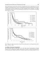
The cell was firstly operated in the MFC mode over a period of 90 hours with potassium
permanganate used as the electron acceptor. At the instant of adding the catholyte the
system produced 1.7mV. Measurements were taken as frequently as was possible without a
system in place for automatic sampling. The recorded voltages and calculated current
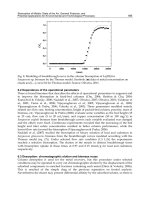
densities for this period are shown in Figure 6. The cell was not kept under temperature
controlled conditions and it was observed that the voltages increased and decreased
throughout the days with the fluctuating temperature. To investigate this more closely
between the period of 64 and 76 hours from start both the voltage and temperature were
recorded every fifteen minutes as shown in Figure 7.
The maximum voltage obtained throughout the cell running time occurred during this
period. At 74.5 hours from start a voltage of 28.7mV was observed at a temperature of 39˚C.
The corresponding current density is 404.8mA/m
2
with power normalised by anode surface
area of 11.62mW/m
2
and volumetric power 50.05mW/ m
3
. The system failed to produce
hydrogen when operated as an MEC. Further experimentation is needed to determine if the
reason for this was due to the presence of oxygen despite the cell being flushed with helium
or due to the short running time and therefore lack of highly developed bacterial
communities.
Progress in Biomass and Bioenergy Production
420
A
0
5
10
15
20
25
30
0 102030405060708090
Time from start (hours)
Voltage produced (mV)
Potassium Permanganate Catalyst Potassium Permanganate replaced
0
50
100
150
200
250
300
350
400
450
0 1 20 22 44 46 47 50 66 68 70 73 75 89
Time from start (hours)
Current Density (mA/m2)
B
Fig. 6. A) Recorded voltages from start time (Oh) to end time (90h) and B) calculated current
densities over the same period.
Microbial Conversion of Biomass: A Review of Microbial Fuel Cells
421
0
5
10
15
20
25
30
35
64 65 67 68 69 70 72 73 74 75
Time (hours)
Voltage (mV)
10
15
20
25
30
35
40
45
50
Temp (˚C)
Voltage Temperature
0
5
10
15
20
25
30
35
64 65 67 68 69 70 72 73 74 75
Time (hours)
Voltage (mV)
10
15
20
25
30
35
40
45
50
Temp (˚C)
Voltage Temperature
Fig. 7. Effect of varying temperature on voltage produced for the period 64 to 76 hours after
start.
4.2 Design 2
Many possibilities could be identified to explain the low performance of the cell. The most
obvious ones are the high internal resistance, inadequate bacterial growth and
unsuitable/insufficient organic matter present. A combination of these may even have been
the case.
4.2.1 Design and construction
In order to overcome the original cells problems several improvements were proposed.
These included replacing the Entrant material with an anion exchange membrane, using
sewage as both the bacteria source and the organic matter and increasing the amount of
electrode material. An illustration of these improvements can be found in Figures 8 and 9.
Figure 9 shows a photographic image of the completed reactor.
Fig. 8. Two dimensional diagram of the improved cell
Progress in Biomass and Bioenergy Production
422
Fig. 9. Photograph of improved cell
As shown in Figures 8 and 9, the single electrodes which were held in place by copper
clamps have been replaced by double electrodes held by a stainless steel frame. This
adjustment was made for two reasons. Firstly the increased surface area of anode and
cathode material will allow for more bacterial growth and more reactions occurring in the
cathode chamber. Secondly the copper clamps used previously were highly susceptible to
rust causing them to need to be replaced frequently and the chamber contents to be
contaminated by rust particles. Due to the constant immersion of the electrodes in water
stainless steel was the only viable option to use to hold the electrodes in place and resist
corrosion.
The Entrant membrane has been replaced with an anion exchange membrane designed
especially for such applications. The new membrane may provide better facilitation for
protons than the previous material used. Due to the small amount required a free sample
was able to be obtained however larger quantities can be exceedingly expensive. Initially
bacteria were sourced from river water which should provide an adequate array of bacteria
including many exo-electrogens. However as wastewater is more nutrient rich it was
thought that it may also be more bacteria rich. The experiment was carried out in the same
manner as the previous trial with the same buffer solution used in the anode and cathode
chambers.
4.2.2 Results and discussions
The improved cell was operated over a period of 55 days, almost three times longer than the
original cell. At the instant of adding the potassium permanganate the cell produced only
0.4mV as compared with the 1.7mV seen in the previous cell. The initial sharp increase in
voltage over the first few hours that was demonstrated by the first cell was not seen in the
improved cell. The voltage instead was stagnant around the 0.4mV mark for some time.
The recorded voltages and calculated current densities are shown below in Figures 10 and
11 respectively. The maximum cell voltage observed was 4.73mV which occurred 17 days
after start time. The corresponding current density is 66.75mA/m
2
with power normalised
by anode surface area of .316mW/m
2
and volumetric power 1.36mW/ m
3
.
Microbial Conversion of Biomass: A Review of Microbial Fuel Cells
423
Fig. 10. Recorded voltages from start time (4/8/10) to end time (28/9/10)
Fig. 11. Calculated current densities over the same period
Progress in Biomass and Bioenergy Production
424
Rather than improving the performance of the fuel cell, the adjustments made hampered
the performance. Time did not permit for a lengthy investigation into the reasons for this
however several conclusions can be theorised. It can be concluded that the addition of the
stainless steel frame housing the electrodes considerably increased the internal resistance
of the cell. This can be deduced by comparing the resistivity of the formerly used copper
and the stainless steel which replaced it. The Physics Hypertext book gives copper and
stainless steel resistivity of 17.1 (nΩm) and 720 (nΩm) respectively (Alert, 2010). The
stainless steel design therefore increased the resistivity the electron travels through by
over 40 times that in the original design. This effect was unavoidable as stainless steel was
the only metal capable of withstanding the fuel cell conditions without suffering from
corrosion. This increased internal resistance would explain a drop in current density as
seen in the results.
As discussed previously bacteria growth is extremely important to the voltage produced. It
is well known that bacteria favour warm conditions for growth (Answers.com, 2010) . Due
to the use of human effluent in the improved cell, health regulations required that it be
located in an isolated location. The only available areas were either outside or in a poorly
ventilated, cold room. As it was winter at the time of the trial the cell was most often kept at
a temperature of around 15 degrees Celsius. The earlier trial however was conducted during
summer where the cell was kept at a more suitable 25 – 30 degrees Celsius. These
inadequate conditions may have hampered the bacterial growth and decreased the output
voltage as a result. The higher temperature may have also contributed to the higher voltage
in the cathode chamber. Since heat is a catalyst a higher temperature may have speeded up
the reaction in the cathode chamber by causing the protons to have a greater kinetic energy
and collide with a higher number of electrons. The heat related effects were demonstrated in
the previous trial where the temperature and voltage were recorded and compared over a
period of time.
5. Conclusions, outlook and future study
The study presented in this chapter has mainly provided a review of the concept of
microbial conversion of biomass into usable energy. An overview of Microbial Fuel Cells
(MFCs) has been given, and their significance has been outlined. MFC and MEC systems
are recognised as energy production systems with great potentials. The world’s need for
electricity and fuel is ever increasing and so is the need for clean, renewable methods to
produce these things. Microbial cells have the advantage of running off widely available
sources of energy including waste water and food scraps. These are things produced by
every home around the globe including remote areas and in developing countries.
The study also discussed the design and construction details of two MFCs and presented the
results of tests carried out with the constructed cells. The results demonstrate that further
work is needed before MFCs could become a commercial success. Reducing the expenses of
building and operating an MFC/MEC system as well as increasing cell efficiencies are
ongoing issues for the technology. Further research is also required in many areas
particularly in the area of catalysts as the cathode with the inclusion of the catalyst has been
found to account for almost fifty percent of the cost of an MFC/MEC (Call et al., 2009).
Future studies should focus on the incorporation of bacteria on the cathode to replace the
current techniques.
Microbial Conversion of Biomass: A Review of Microbial Fuel Cells
425
Optimal methods for producing a biocathode have not been thoroughly investigated (Logan
et al., 2008) however it has been shown that an effective way to produce a biocathode is to
reverse the polarity of an MEC (Rozendal et al., 2008; Jeremiasse et al., 2009).
Membrane’s also increase the expense of a system so architectures which do not require a
membrane are obviously more desirable although they too have their drawbacks.
Membrane fabric offers an inexpensive alternative to cation and anion exchange membranes
but further investigation as to their comparative performance must be undertaken.
Nevertheless MFC and MEC technology is relatively new but advancements to the
technology have been rapid and should continue at this pace resulting in higher efficiencies,
lower costs and a scalable reactor design in the not too distant future.
6. References
Alert, G. (2010). Electric Resistance. Available from: <o/electric-
resistance/>.
Answers.com. (2010). What conditions promote bacterial growth? , Available from:
<
Ballard Power Systems. (24 January 2008). How Fuel Cells Work. Available from:
< />_Cells_Work.htm>.
Blair, S. (2008). Monash fuels the next generation of Hybrid cars. 17 January 2010, Available
from: <
Call, D. and B. E. Logan (2008). "Hydrogen Production in a Single Chamber Microbial
Electrolysis Cell Lacking a Membrane."
Call, D. and B. E. Logan (2008). "Hydrogen Production in a Single Chamber Microbial
Electrolysis Cell Lacking a Membrane." Environ. Sci. Technol. Vol. 42, No.9, pp.
3401–3406.
Call, D. F., M. D. Merrill and B. E. Logan (2009). "High Surface Area Stainless Steel Brushes
as Cathodes in Microbial Electrolysis Cells." Environ. Sci. Technol. Vol. 43, No.6, pp.
2179–2183.
Chae, K., M. Jinchoi, K. Kim, F. F. Ajayi, I. Chang and I. S. Kim (2009). "A Solar-Powered
Microbial Electrolysis Cell with a Platinum Catalyst-Free Cathode To Produce
Hydrogen." Environ. Sci. Technol. Vol. 43, No.24, pp. 9525–9530.
Danigelis, A. (2009). What a Great Vintage of Hydrogen You Have. Available from:
< />have.html>.
FCTec. (2010). Fuel Cell Basics. Available from: <
Field, S. Q. (2008). Chapter 3: Electrochemistry. Available from:
<
Finfacts-Team. (2009). International Energy Outlook 2009: World energy consumption
projected to rise 44% from 2006 to 2030; Carbon emissions to jump more than 39%
without new policies. 21 March 2010, Available from:
<
He, Z. and L. T. Angenent (2006). "Application of Bacterial Biocathodes in Microbial Fuel
Cells." Electroanalysis. Vol. 18, No.19-20.
Hopwood, N. and J. Cohen. (2000). Greenhouse Gases and Society. 13 February 2010,
Available from: <
Progress in Biomass and Bioenergy Production
426
HowStuffWorks.com. (2000). What are all the different ways to store energy besides using
rechargeable batteries? 21 March 2010, Available from:
<
Jeremiasse, A. W., H. V. M. Hamelers and C. J. N. Buisman (2009). "Microbial electrolysis cell
with a microbial biocathode." Elsevier: Bioelectrochemistry, Vol. 78, No.1, pp. 39-43.
Knapp, B. (2002). Hydrogen and the Noble Gases. Atlantic Europe Publishing Company
Limited, 0717275736.
Liu, H., S. Grot and B. E. Logan (2005). "Electrochemically Assisted Microbial Production of
Hydrogen from Acetate." Environmental Science & Technology. Vol. 39, No.11, pp.
4317-4320.
Logan, B. E. (2008). Microbial Fuel Cells. Wiley, 0470239484.
Logan, B. E., D. Call, S. Cheng, H. Hamelers, T. Sleutels, A. Jeremiasse and R. Rozendal
(2008). "Microbial Electrolysis Cells for High Yield Hydrogen Gas Production from
Organic Matter." Environ. Sci. Technol. Vol. 42, No.23, pp. 8630–8640.
Logan, B. E. and S. Cheng (2008). "Evaluation of catalysts and membranes for high yield
biohydrogen production via electrohydrogenesis in microbial electrolysis cells
(MECs)." Water Science & Technology Vol. 59, No.10.
Logan, B. E., B. Hamelers, R. Rozendal, U. Schroder, J. Keller, S. Freguia, P. Aelterman, W.
Verstraete and K. Rabaey (2006). "Microbial Fuel Cells: Methodology and
Technology." Environmental Science & Technology. Vol. 40, No.17, pp. 5181-5192.
Markusic, M. (2010). How is Renewable Energy from Chocolate Possible? . Available from:
< />energy/articles/37144.aspx>.
Nice, K. and J. Strickland. (2010). How fuel cells work. Available from:
< />cell5.htm>.
Plumer, B. (2009). Why Energy Storage Yes, Energy Storage Needs Love. 21 March 2010,
Available from: < />energy-storage-needs-love>.
Putnam, S. C. (2007). The Mechanical Battery. 12 January 2010, Available from:
<
Rayner, J. (2008). Flywheel energy storage. 20 February 2010, Available from:
<
Rozendal , R. A., A. W. Jeremiasse, H. V. M. Hamelers and C. J. N. Buisman (2008).
"Hydrogen Production with a Microbial Biocathode." Environ. Sci. Technol. Vol. 42,
pp. 629-634.
Sun, M., G P. Sheng, L. Zhang, C R. Xia, Z X. Mu, X W. Liu, H L. Wang, H Q. Yu, R. Qi,
T. Yu and M. Yang (2008). "An MEC-MFC-Coupled System for Biohydrogen
Production from Acetate." Environmental Science & Technology. Vol. 42, No.21, pp.
8095-8100.
You, S. J., N. Q. Ren, Q. L. Zhao, J. Y. Wang and F. L. Yang (2009). "Power Generation and
Electrochemical Analysis of Biocathode Microbial Fuel Cell Using Graphite Fibre
Brush as Cathode Material." Fuel Cells. , No.5, pp. 588–596.
Zyga, L. (2009). Liquid Battery Offers Promising Solar Energy Storage Technique. 21 March
2010, Available from: <
Part 7
Bio-Economic
22
Methods for Structural and Parametric
Synthesis of Bio-Economic Models
Darya V. Filatova
Jan Kochanowski University in Kielce, Kielce,
Poland
1. Introduction
The communities of animals and plants are some examples of biological systems where
population dynamics
()
d
t ∈X R ,
[
]
01
,ttt∈ , depends not only on environmental variability
and internal transformations, but also on human control factor
()
r
t ∈u R ,
[
]
01
,ttt∈ . (We
will call also
()
tX
a phase variable and
()
tu
a control variable.)
Since many biological systems have to stay in some dynamic equilibrium, the control
representing the action, decision, or policy of the decision-makers can only correct the
system development with moderate effects on its natural behavior. In this case controllers
are interested in the selection of a nonaticipative decision among the ones satisfying all the
changes of existence conditions and inter-connections among different communities.
Suppose that the controller is interested in renewable resource management (fishery or
forestry) over the planning horizon
[
]
01
,tt .
The goal of this task is maximization with respect to
() ()
tUt∈u (
()
Ut is a given metric
space,
[
]
01
,ttt∈ ) of the functional
() ()
()
() ()
()
() ()
()
1
0
00 1
,sup,, ,
t
t
uU
ft t t dt t t
ψ
∈
⋅⋅= +
Xu X u X XJ
(1.1)
subjected to the constraints
() () ()
()
,,dt t t tdtXXu
= T , (1.2)
() ()
()
10 1
,0tt
ψ
≤XX
, (1.3)
() ()
()
20 1
,0tt
ψ
=XX
; (1.4)
()
()
[
]
01 1
, 0, , , 1, ,
i
gt t t tt i≤∀∈ =X
, (1.5)
()
()
2
, 0, 1, ,
j
tt j
φ
≤=u
, (1.6)
Progress in Biomass and Bioenergy Production
430
where
() ()
()
,,tt tXu
T is an operator of a mathematical model of the resource
()
tX ,
:
dr
f ××→RR R R, :
dr d
ϕ
××→RR R R,
0
:
dd
ψ
×→RR R,
1
1
:
kdd
ψ
×→RR R,
2
2
:
kdd
ψ
×→RR R, :
d
i
g ×→RR R (
1
1 i≤≤ ), :
r
j
φ
×→RR R(
2
1 j≤≤ ); d , ,r
1
,k
2
,k
1
, ∈
2
N , and
()
sup ⋅ is the least upper bound.
The task (1.1) - (1.6) is formulated as an optimal control task [Milyutin & Osmolovski, 1998].
Its solution and accuracy of this solution depend on many different factors, mainly on the
successful selection of the object equation. The wrong specification of a model and as a
consequence wrong parametric identification can lead to erroneous solution of (1.1) - (1.6).
Since the factor of uncertainty is always present at the resource description, it is reasonable
to take (1.2) as an stochastic differential equation (SDE).
Let the renewable resource describes a certain population of fish, which natural growth rate
depends on different biological parameters. Very often these parameters are evaluating over
the time because environmental conditions are not constant. In this case it is reasonable to
treat the parameters of SDE as the bivariate functions (or the SDE with time-varying
parameters). Since the structure of the SDE is selected, the next step is the construction of the
estimation procedure.
It is not easy to describe the bivariate functions by means of certain functional forms.
Flexible model does not assume any specific form of the functions. This data-analytic
approach called nonparametric regression can be found in statistical literature. However the
direct application of the ideas does not bring desired results. The improvements of the
identification procedures were presented in [Fan at al. 2003]. The main idea of this work was
based on the discretization of the SDE and further approximation of parameter functions by
constants at the discretization points. It is clear that the accuracy of the estimates depends on
the accuracy of the discretization method. To overcome this problem we propose to consider
bivariate functions as an control functions and solve the identification task as an optimal
control problem using the maximum principle.
The rest of the paper is organized as follows. The second section is dedicated to the system
analysis of a bio-economic models. The third section presents the identification methods
based on the ideas [Bastogne at al., 2007], [Hansen & Penland, 2007], [Hurn at al., 2003],
[Jang at al., 2003], [McDonald & Sandal, 1998], [Shoji & Ozaki, 1998]. The fourth section
shows the solution for the bivariate functions. The paper is ended by the conclusions.
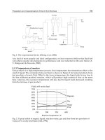
2. System analysis of a bio-economic model
2.1 Problems of structural and parametric synthesis
The mathematical description of any bio-economic model requires taking into account all
the elements of the system and all the interrelations among them. Detailed analysis of the
“complete” model allows to forecast its behavior and introduce optimal management
strategies. Unfortunately, this analysis is mathematically difficult. From one side it is
impossible to detect all the elements and nature of their interconnections. From other side
there are several sources of uncertainty: the growth, mortality, reproduction rate vary in
random manner causing random effects on genetics and age structure of exploited
population; the price of the resource depends on economical situation on stock markets,
political situation, climate and etc.
Distinctive property of each stochastic object is contained with ambiguous respond on the
same input signals. Even for simplest one-dimensional object and for non-stochastic input
signal, output signal of stochastic object can’t be considered as deterministic one. For output
Methods for Structural and Parametric Synthesis of Bio-Economic Models
431
variable of this objects class scattering growths with increasing of objects “noise properties”.
For that reason uncertainty in behavior can be explained by noise influence that in addition
brings deficiency of a priori information about system.
Therefore, it is impossible to detect a model, whose properties and mathematical description
would correspond to the “exact” behavior of the system. Every mathematical model will be
only similar with the system. In this case model selection has to be done under two groups
of disjoint requirements:
• the main features of the system have to be reflected as precise as possible (the degree of
similarity);
• existence of the theoretical methods, which allow to use the model for forecast,
optimization, control, etc.
The dynamics of bio-economic system (1.2) can be described by means of its states. Let a
union of the values of the phase variable
()
d
t ∈X R
,
[
]
01
,ttt∈
, denote the state
*
t
∈SS (
*
S
is some space) of the system in time
t ,
*
t+Δ
∈SS denote the state in time t +Δ (where Δ is
time increment,
Δ∈R ,
1
0 t<Δ<
). The dynamics of the system (1.2) can be written as
( ) () () ()
()
*
,,tt tt+Δ − =S-STSC,G, (2.1)
where
()
tT is an operator of a mathematical model,
() () () ()
{
}
01
, , ,
k
ttt t=Ccc c
is a set of
k parameters,
() () () ()
{
}
01
, , ,
k
tttt=Ggg g is the set of the structural relations of the phase
variables of the system.
The formalization of the model (2.1) depends on the selection of:
- the set of phase variables
()
dn
t
−
∈X R , 0 nd≤<;
- the theoretical method to define
*
S ;
- the structural relations
()
tG among the selected phase variables;
- the parametric identification method for the estimation of the parameters
()
tC .
Even though it is well known task, the problem of the object (2.1) formalization can be
solved by a few mathematical tools. Among basic groups of exact and approximated
methods, which are used to solve the problem, we can name: exact methods, methods of
task simplification, methods of the task linearization, numerical methods, methods of
integral transformation, method of infinite series, variation methods, and methods of
reduction to the systems of the ordinary differential equations.
2.2 Stochastic differential equation as a bio-economic model
We consider a certain population of fish, whose size at time t is denoted by
()
Xt∈ R ,
[
]
01
,ttt∈ . This population has a natural growth rate
()
()
*
,tXt
ϕ
:
()
()
()
*
,
dX t
tXt
dt
ϕ
=
,
()
00
Xt X=
, (2.2)
where
*
:
ϕ
×→RR R is assumed to be a concave function with given properties.
Fish stock
()
Xt
has natural fluctuations and is subjected to many stochastic effects. To take
them into account we have to improve the model (2.2) adding some stochastic terms. In fact
Progress in Biomass and Bioenergy Production
432
the increment
()
dX t
dt
is not a deterministic, thus the structure of the model (2.2) has to be
reorganized.
Let
{
}
()
0
,, ,
t
t
≥
Ω PFF be a stochastic basis satisfying the usual conditions. Let the phase
variable be :X Ω→
R ,
ω
∈Ω ,
()
Xx
ω
= and
()
[
]
{
}
01
,,vt t t t∈ be a continuous stochastic
process, defined on
{
}
()
0
,, ,
t
t
≥
Ω PFF , such that its mean value function
()
0vt=
E for
every
[
]
∈
01
,ttt and
()
0
0vt = . By the intuition we add the term
()
vt to (2.2)
()
() ()
()
**
,,
dX t
tXt vt
dt
ϕ
= ,
()
00
Xt X= ,
[
]
01
,∈ttt, (2.3)
where
**
:
ϕ
××→:R R R R
.
The model (2.3) presents a stochastic differential equation, whose solution depends on the
selection of the stochastic process
()
vt and its properties. Let the process be the Brownian
motion process
()
[
]
{
}
01
,,Bt t t t∈ . This process has many useful theoretical properties,
namely
1.
the independence and stationarity of the increments
()()
Bt h B h
τ
+− + for every
[
]
τ
>∈
01
,ttt and every 0h > ;
2.
the mean square continuity of
()
Bt
for every
[
]
01
,ttt∈
;
3.
the regularity conditions, i.e.
()
2
0
Bt
<∞
E
and
()()
var Bt h B h
τ
+− + <∞
(where
[
]
⋅E denotes the expectation operator and
[
]
var ⋅ denotes the variance operator) .
We replace the stochastic term
()
vt
by
()
Bt
and rewrite the model (2.3) as a stochastic
differential equation
() ()
()
()
()
()
,,dXt atXt dt btXt dBt=+ ,
()
00
Xt X=
, (2.4)
or as an integral equation
() ( ) ( )
()
()
()
()
00
0
,,
tt
tt
Xt Xt a X dt b X dB
ττ ττ τ
−= +
, (2.5)
where :
a ×→RR R and :b ×→RR R are Baire functions,
()
dB t is an increment of the
Brownian motion process. The first integral in (2.5) will be a mean square Riemann integral,
whereas the second one will be the Ito stochastic integral. Equation (2.4) is therefore called
Ito stochastic differential equation.
Equation (2.4) can be used for the description of the object (1.2). In this case, the optimal
control solution of the task (1.1) – (1.6) requires the existence and uniqueness of the solution
of the equation (2.4). This solution can be treated in strong or weak sense. The SDE (2.4) has
• a unique strong solution, if any two solutions
()
Xt and
()
Xt
,
[
]
01
,ttt∈ , coincide by
all trajectories of the process so that
Methods for Structural and Parametric Synthesis of Bio-Economic Models
433
[]
01
,
sup 0 0
tt
ttt
XX
∈
−>=
p
,
• a unique weak solution, if its solutions coincide by probability, but not obligatory by
trajectories.
Let us consider the solution of SDE (2.3) only in the strong sense. The following theorem
guaranties the existence and uniqueness of the strong solution for (2.4).
Theorem 2.1. The solution of equation (2.3)
()
Xt (
[
]
01
,ttt∈ ) exists and is unique in strong
sense, if the following conditions are held.
A1 (Measurability):
()
,atx and
()
,b t x are jointly
2
L − measurable in
()
[
]
01
,,tx t t∈×R .
A2 (Lipschitz condition): There exists a constant 0K > such that
()
()
,,atx at
y
Kx
y
−≤−
and
()
()
,,btx bt
y
Kx
y
−≤−
for all
[
]
01
,∈ttt and
,xy∈R
.
A3 (Linear growth bound): There exists a constant 0K > such that
()
()
2
2
2
,1≤+atx K x
and
()
()
2
2
2
,1≤+btx K x
for all
[
]
01
,ttt∈ and x ∈ R .
A4 (Initial value):
()
0
Xt is
0
t
A
-measurable with
()
(
)
2
0
Xt <∞E .
In particular, assumptions (A2) and (A3) ensure that a solution of an SDE does not explode.
This is very important to insure the stability of a numerical approximation of
()
Xt
,
[
]
01
,ttt∈ , and avoid the “stiffness” and “ill-posed” problems. Among other properties are
boundedness and continuity on
[
]
01
,ttt∈ , which guarantee the existence of an adjoint
system and partly the optimality of the solution of the task (1.1) – (1.6).
The description of a bio-economic model is not completed since we have not introduce the
set of parameters
()
tC
,
[
]
01
,ttt∈
, in the structure (2.1). Denoting the parameters as
()
q
t ∈θ R
we rewrite (2.4)
() () ()
()
() ()
()
()
,; ,;dX t a t X t t dt b t X t t dB t=+θθ
,
()
00
Xt X=
. (2.6)
It is clear that the values of the parameters
()
tθ
are unknown and have to be evaluate by
the proper estimation procedure. If one uses the maximum likelihood estimation method
the following can be helpful.