PID Control Implementation and Tuning Part 12 potx
Bạn đang xem bản rút gọn của tài liệu. Xem và tải ngay bản đầy đủ của tài liệu tại đây (1.66 MB, 20 trang )
Pre-compensation for a Hybrid Fuzzy PID Control of a Proportional Hydraulic System 213
lower the threshold
e
0
or close to the set point, the control system shift switch to the PID
controller, which has better accuracy near the set point.
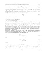
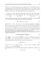
Fig. 14. Block diagram of pre-compensation of a hybrid Fuzzy PID controller.
4. Experimental Description
The specifications of a PHS are depicted in figures. 15, 16 and table 3 respectively. Figure 15
shows a diagram of the tested system. The position control of a PHS procedure is described
as follows: upon the intended initial and ending position of the piston (stroke) are given, the
computer receives the feedback signal through DAQ card (A/D) from linear potentiometer,
realizes various control algorithm and transmits a control signal through DAQ card (D/A)
and amplifier card to proportional valve. The spool displacement of proportional valve is
proportional to the input signal.
Fig. 15. PC-Based position control of a PHS.
PC-Based
DAQ Card
Amplifier
Card
Proportional
Valve
Cylinder
Potentiometer
G
F
PHS
Pre-compensator
y
m
y
m
e
e
u
y
p
K
1
Fuzzy Controller
PID
PID Controller
?ee
0
Selector
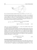
Fig. 16. The experimental setup.
Elements Descriptions
Cylinder piston diameter 16 mm, piston rod diameter 10 mm,
stroke 200 mm
Proportional valve
(4/3 closed-center
spool, overlapped
)
directly actuated spool valve, grade of filtration 10 m,
nominal flow rate 1.5l/min (at p
N
= 5 bar/control
edge), leakage oil flow < 0.01 l/min (at 60 bar), nominal
current 680 mA, resolution < 1 mA, setting time of signal
jump 0…100% = 60 ms, repetition accuracy < 1%
Pump
(supply pressure)
60 bar
Linear potentiometer output voltage 0…10V, measuring stroke 200 mm,
linearity tolerance 0.5%
Amplifier card
set point values
10 VDC, solenoid outputs (PWM signal)
24 V, dither frequency 200 Hz, max current 800 mA,
DAQ Card
(NI 6221 PCI)
analog input resolutions 16 bits (input range 10V),
output resolutions 16 bits (output range 10V), 833 kS/s (6
s full-scale settling)
Operating systems &
Program
Windows XP, and LabVIEW 8.6
Table 3. Specifications of a PHS.
5. The Experimental Results
The control algorithms described in section 2.3, 2.4, and 2.5 were hybridized and applied to
the PHS using by LabVIEW, Nation Instruments as the development platform and shown in
figure 17.
PID Control, Implementation and Tuning214
Fig. 17. The control algorithm are used and developed by LabVIEW program.
In our experiments we compare the performance of conventional hybrid fuzzy PID
controller to the proposed pre-compensation of a hybrid fuzzy PID controller. A testing of
response of the system was performed using a square wave input. The parameter values of
the pre-compensation of a hybrid fuzzy PID controller were experimentally determined to
be:
K
1
= 0.93, K
P
= 5.6, e
0
= 0.92. Figures. 18 and 19 shows the output response of a
conventional hybrid fuzzy PID system compared to the pre-compensation of a hybrid fuzzy
PID system. It is found that the pre-compensation of a hybrid fuzzy PID controller gives the
most satisfying results of rise time, overshoot, and steady state error.
Fig. 18. Output response of conventional (hybrid fuzzy PID) controller.
Position (mm.)
200
160
120
80
40
00
00
05
10
Time (seconds)
Position (mm.)
200
160
120
80
40
00
00
05
10 Time (seconds)
Fig. 19. Output response of a proposed controller.
6. Conclusions
The objective of this study, we proposed the pre-compensation of a hybrid fuzzy PID
controller for a PHS with deadzones. The controller consists of a fuzzy pre-compensator
followed by fuzzy controller and PID controller. The proposed scheme was tested
experimentally and the results have superior transient and steady state performance,
compared to a conventional hybrid fuzzy PID controller. An advantage of the present
approach is that an existing hybrid fuzzy PID controller can be easily modified into the
control structure by adding a fuzzy pre-compensator, without having to retune the internal
variables of the existing hybrid fuzzy PID controller.
In this study, an experimental research, so we do not address the problem of analyzing the
stability of the control scheme in this paper. This difficult but important problem is a topic
of ongoing research.
7. References
Chin-Wen Chuang and Liang-Cheng Shiu.(2004). CPLD based DIVSC of hydraulic position
control systems.
Computers and Electrical Engineering. Vol.30, pp.527-541.
T. Knohl and H. Unbehauen. (2000). Adaptive position control of electrohydraulic servo
systems using ANN.
Mechatronics. Elsevier Science Ltd. vol. 10, pp. 127-143.
Bora Eryilmaz, and Bruce H. Wilson. (2006). Unified modeling and analysis of a
proportional valve.
Journal of the Franklin Institute, pp. 48-68.
L.A. Zadeh. (1965). Fuzzy sets.
Information and Control. vol.8, pp.338-1588.
E.H. Mandani and S. Assilian. (1975). An experiment in linquistic synthsis with a fuzzy logic
control.
Machine Studies. vol.7, pp. 1-13.
Isin Erenoglu, Ibrahim Eksin, Engin Yesil, and Mujde Guzelkaya. (2006). An Intelligent
Hybrid Fuzzy PID Controller,”
Proceedings 20
th
European Conference on Modelling and
Simulation © ECMS. ISBN : 0-9553018-0-7.
Roya Rahbari, and Clarence W. de Silva. (2000). Fuzzy Logic Control of a Hydraulic System.
©IEEE, ISBN: 0-7803-58112-0, pp. 313- 318.
Pre-compensation for a Hybrid Fuzzy PID Control of a Proportional Hydraulic System 215
Fig. 17. The control algorithm are used and developed by LabVIEW program.
In our experiments we compare the performance of conventional hybrid fuzzy PID
controller to the proposed pre-compensation of a hybrid fuzzy PID controller. A testing of
response of the system was performed using a square wave input. The parameter values of
the pre-compensation of a hybrid fuzzy PID controller were experimentally determined to
be:
K
1
= 0.93, K
P
= 5.6, e
0
= 0.92. Figures. 18 and 19 shows the output response of a
conventional hybrid fuzzy PID system compared to the pre-compensation of a hybrid fuzzy
PID system. It is found that the pre-compensation of a hybrid fuzzy PID controller gives the
most satisfying results of rise time, overshoot, and steady state error.
Fig. 18. Output response of conventional (hybrid fuzzy PID) controller.
Position (mm.)
200
160
120
80
40
00
00
05
10
Time (seconds)
Position (mm.)
200
160
120
80
40
00
00
05
10 Time (seconds)
Fig. 19. Output response of a proposed controller.
6. Conclusions
The objective of this study, we proposed the pre-compensation of a hybrid fuzzy PID
controller for a PHS with deadzones. The controller consists of a fuzzy pre-compensator
followed by fuzzy controller and PID controller. The proposed scheme was tested
experimentally and the results have superior transient and steady state performance,
compared to a conventional hybrid fuzzy PID controller. An advantage of the present
approach is that an existing hybrid fuzzy PID controller can be easily modified into the
control structure by adding a fuzzy pre-compensator, without having to retune the internal
variables of the existing hybrid fuzzy PID controller.
In this study, an experimental research, so we do not address the problem of analyzing the
stability of the control scheme in this paper. This difficult but important problem is a topic
of ongoing research.
7. References
Chin-Wen Chuang and Liang-Cheng Shiu.(2004). CPLD based DIVSC of hydraulic position
control systems.
Computers and Electrical Engineering. Vol.30, pp.527-541.
T. Knohl and H. Unbehauen. (2000). Adaptive position control of electrohydraulic servo
systems using ANN.
Mechatronics. Elsevier Science Ltd. vol. 10, pp. 127-143.
Bora Eryilmaz, and Bruce H. Wilson. (2006). Unified modeling and analysis of a
proportional valve.
Journal of the Franklin Institute, pp. 48-68.
L.A. Zadeh. (1965). Fuzzy sets.
Information and Control. vol.8, pp.338-1588.
E.H. Mandani and S. Assilian. (1975). An experiment in linquistic synthsis with a fuzzy logic
control.
Machine Studies. vol.7, pp. 1-13.
Isin Erenoglu, Ibrahim Eksin, Engin Yesil, and Mujde Guzelkaya. (2006). An Intelligent
Hybrid Fuzzy PID Controller,”
Proceedings 20
th
European Conference on Modelling and
Simulation © ECMS. ISBN : 0-9553018-0-7.
Roya Rahbari, and Clarence W. de Silva. (2000). Fuzzy Logic Control of a Hydraulic System.
©IEEE, ISBN: 0-7803-58112-0, pp. 313- 318.
PID Control, Implementation and Tuning216
M. Parnichkul and C. Ngaecharoenkul. (2000). Hybrid of Fuzzy and PID in Kinematics of a
Pneumatic System.
Proceeding of IEEE Industrial Electronics Society. IEEE Press, vol.
2 no. 2, pp.1485-1490.
Hao Liu, Jae-Cheon Lee, and Bao-Ren Li. (2007). High Precision Pressure Control of a
Pneumatic Chamber using a Hybrid Fuzzy PID Controller.
International Journal of
Precision Engineering and Manufacturing
, Vol.8, No3. pp. 8-13.
Jong-Hwan Kim, Kwang-Choon Kim, and Edwin K.P. Chong. (1994). Fuzzy
Precompensated PID Controllers.
IEEE Transactions on Control System Technology,
Vol.2, No. 4, December, pp. 406-411.
J H. Kim, J H. Park, S W. Lee, E.K.P. Chong. (1994). A Two-Layered Fuzzy Logic
Controller for Systems with Deadzones,”
IEEE Transactions on Industrial Electronics,
Vol. 41, No. 2, April. pp. 155-162.
Chang-chun Li, Xiao-dong Liu, Xin Zhou, Xuan Bao, Jing Huang. (2006). Fuzzy Control of
Electro-hydraulic Servo Systems Based on Automatic Code Generation.
Proceedings
of the Sixth International Conference on Intelligent Systems Design and Applications
(ISDA'06).
Pornjit Pratumsuwan, and Siripun Thongchai. (2009). A Two-Layered Fuzzy Logic
Controller for Proportional Hydraulic System.
Proceeding of 4
th
IEEE International
Conference on
Industrial Electronic and Applications (ICIEA2009), pp. 2778-2781.
Pornjit Pratumsuwan, Siripun Thongchai, and Surapun Tansriwong. (2010). A Hybrid of
Fuzzy and Proportional-Intrgral-Derivative Controller for Electro-Hydraulic
Position Servo System.
Energy Research Journal 1(2), pp.62-67.
A New Approach of the Online Tuning Gain
Scheduling Nonlinear PID Controller Using Neural Network 217
A New Approach of the Online Tuning Gain Scheduling Nonlinear PID
Controller Using Neural Network
Ho Pham Huy ANH and Nguyen Thanh Nam
X
A New Approach of the Online Tuning
Gain Scheduling Nonlinear PID
Controller Using Neural Network
Ho Pham Huy ANH
1
and Nguyen Thanh Nam
2
1
Corresponding author, Ho Chi Minh City University of Technology, Ho Chi Minh City,
Viet Nam
2
DCSELAB, Viet Nam National University Ho Chi Minh City (VNU-HCM), Viet Nam
Abstract
This chapter presents the design, development and implementation of a novel proposed
online-tuning Gain Scheduling Dynamic Neural PID (DNN-PID) Controller using neural
network suitable for real-time manipulator control applications. The unique feature of the
novel DNN-PID controller is that it has highly simple and dynamic self-organizing
structure, fast online-tuning speed, good generalization and flexibility in online-updating.
The proposed adaptive algorithm focuses on fast and efficiently optimizing Gain Scheduling
and PID weighting parameters of Neural MLPNN model used in DNN-PID controller. This
approach is employed to implement the DNN-PID controller with a view of controlling the
joint angle position of the highly nonlinear pneumatic artificial muscle (PAM) manipulator
in real-time through Real-Time Windows Target run in MATLAB SIMULINK
®
environment. The performance of this novel proposed controller was found to be
outperforming in comparison with conventional PID controller. These results can be applied
to control other highly nonlinear SISO and MIMO systems.
Keywords: highly nonlinear PAM manipulator, proposed online tuning Gain Scheduling
Dynamic Nonlinear PID controller (DNN-PID), real-time joint angle position control, fast
online tuning back propagation (BP) algorithm, pneumatic artificial muscle (PAM) actuator
.
1. Introduction
The compliant manipulator was used to replace monotonous and dangerous tasks, which
has enhanced lots of researchers to develop more and more intelligent controllers for
human-friendly industrial manipulators. Due to uncertainties, it is difficult to obtain a
precise mathematical model for robot manipulators. Hence conventional control
methodologies find it difficult or impossible to handle un-modeled dynamics of a robot
manipulator. Furthermore, most of conventional control methods, for example PID
controllers, are based on mathematical and statistical procedures for modeling the system
11
PID Control, Implementation and Tuning218
and estimation of optimal controller parameters. In practice, such manipulator is often
highly non-linear and a mathematical model may be difficult to derive. Thus, as to
accommodate system uncertainties and variations, learning methods and adaptive
intelligent techniques must be incorporated.
Due to their highly nonlinear nature and time-varying parameters, PAM robot arms present
a challenging nonlinear model problem. Approaches to PAM control have included PID
control, adaptive control (Lilly, 2003), nonlinear optimal predictive control (Reynolds et al.,
2003), variable structure control (Repperger et al., 1998; Medrano-Cerda et al.,1995), gain
scheduling (Repperger et al.,1999), and various soft computing approaches including neural
network Kohonen training algorithm control (Hesselroth et al.,1994), neural network +
nonlinear PID controller (Ahn and Thanh, 2005), and neuro-fuzzy/genetic control (Chan et
al., 2003; Lilly et al., 2003). Balasubramanian et al., (2003a) applied the fuzzy model to
identify the dynamic characteristics of PAM and later applied the nonlinear fuzzy model to
model and to control of the PAM system. Lilly (2003) presented a direct continuous-time
adaptive control technique and applied it to control joint angle in a single-joint arm.
Tsagarakis et al. (2000) developed an improved model for PAM. Hesselroth et al. (1994)
presented a neural network that controlled a five-link robot using back propagation to learn
the correct control over a period of time. Repperger et al. (1999) applied a gain scheduling
model-based controller to a single vertically hanging PAM. Chan et al., (2003) and Lilly et al.,
(2003) introduced a fuzzy P+ID controller and an evolutionary fuzzy controller,
respectively, for the PAM system. The novel feature is a new method of identifying fuzzy
models from experimental data using evolutionary techniques. Unfortunately, these fuzzy
models are clumsy and have only been tested in simulation studies. (Ahn and Anh, 2006)
applied a modified genetic algorithm (MGA) for optimizing the parameters of a linear ARX
model of the PAM manipulator which can be modified online with an adaptive self-tuning
control algorithm, and then (Ahn and Anh, 2007b) successfully applied recurrent neural
networks (RNN) for optimizing the parameters of neural NARX model of the PAM robot
arm. Recently, we (Ahn and Anh, 2009) successfully applied the modified genetic algorithm
(MGA) for optimizing the parameters of the NARX fuzzy model of the PAM robot arm.
Although these control systems were partially successful in obtaining smooth actuator motion
in response to input signals, the manipulator must be controlled slowly in order to get stable
and accurate position control. Furthermore the external inertia load was also assumed to be
constant or slowly varying. It is because PAM manipulators are multivariable non-linear
coupled systems and frequently subjected to structured and/or unstructured uncertainties
even in a well-structured setting for industrial use or human-friendly applications as well.
To overcome these drawbacks, the proposed online tuning DNN-PID algorithm in this chapter
is a newly developed algorithm that has the following good features such as highly simple and
dynamic self-organizing structure, fast learning speed, good generalization and flexibility in
learning. The proposed online tuning DNN-PID controller is employed to compensate for
environmental variations such as payload mass and time-varying parameters during the
operation process. By virtue of on-line training by back propagation (BP) learning algorithm
and then auto-tuned gain scheduling K and PID weighting values K
p
, K
i
and K
d
, it learns well
the nonlinear robot arm dynamics and simultaneously makes control decisions to both of
joints of the robot arm. In effect, it offers an exciting on-line estimation scheme.
This chapter composes of the section 1 for introducing related works in PAM robot arm
control. The section 2 presents procedure of design an online tuning gain scheduling DNN-
PID controller for the 2-axes PAM robot arm. The section 3 presents and analyses
experiment studies and results. Finally, the conclusion belongs to the section 4.
2. Control System
2.1. Experimental apparatus
The PAM manipulator used in this paper is a two-axis, closed-loop activated with 2
antagonistic PAM pairs which are pneumatic driven controlled through 2 proportional
valves. Each of the 2-axes provides a different motion and contributes to 1 degree of
freedom of the PAM manipulator (Fig. 1). In this paper, the 1
st
joint of the PAM manipulator
is fixed and proposed online tuning Gain Scheduling neural DNN-PID control algorithm is
applied to control the joint angle position of the 2
nd
joint of the PAM manipulator. A general
configuration of the investigated 2-axes PAM manipulator shown through the schematic
diagram of the 2-axes PAM robot arm and the experimental apparatus presented in Fig.1
and Fig.2, respectively.
Fig. 1. Working principle of the 2-axes PAM robot arm.
The experiment system is illustrated in Fig.2. The air pressure proportional valve
manufactured by FESTO Corporation is used. The angle encoder sensor is used to measure
the output angle of the joint. The entire system is a closed loop system through computer.
First, initial control voltage value u
0
(t)=5[V] is sent to proportional valve as to inflate the
artificial muscles with air pressure at P
0
(initial pressure) to render the joint initial status.
Second, by changing the control output u(t) from the D/A converter, we could set the air
A New Approach of the Online Tuning Gain
Scheduling Nonlinear PID Controller Using Neural Network 219
and estimation of optimal controller parameters. In practice, such manipulator is often
highly non-linear and a mathematical model may be difficult to derive. Thus, as to
accommodate system uncertainties and variations, learning methods and adaptive
intelligent techniques must be incorporated.
Due to their highly nonlinear nature and time-varying parameters, PAM robot arms present
a challenging nonlinear model problem. Approaches to PAM control have included PID
control, adaptive control (Lilly, 2003), nonlinear optimal predictive control (Reynolds et al.,
2003), variable structure control (Repperger et al., 1998; Medrano-Cerda et al.,1995), gain
scheduling (Repperger et al.,1999), and various soft computing approaches including neural
network Kohonen training algorithm control (Hesselroth et al.,1994), neural network +
nonlinear PID controller (Ahn and Thanh, 2005), and neuro-fuzzy/genetic control (Chan et
al., 2003; Lilly et al., 2003). Balasubramanian et al., (2003a) applied the fuzzy model to
identify the dynamic characteristics of PAM and later applied the nonlinear fuzzy model to
model and to control of the PAM system. Lilly (2003) presented a direct continuous-time
adaptive control technique and applied it to control joint angle in a single-joint arm.
Tsagarakis et al. (2000) developed an improved model for PAM. Hesselroth et al. (1994)
presented a neural network that controlled a five-link robot using back propagation to learn
the correct control over a period of time. Repperger et al. (1999) applied a gain scheduling
model-based controller to a single vertically hanging PAM. Chan et al., (2003) and Lilly et al.,
(2003) introduced a fuzzy P+ID controller and an evolutionary fuzzy controller,
respectively, for the PAM system. The novel feature is a new method of identifying fuzzy
models from experimental data using evolutionary techniques. Unfortunately, these fuzzy
models are clumsy and have only been tested in simulation studies. (Ahn and Anh, 2006)
applied a modified genetic algorithm (MGA) for optimizing the parameters of a linear ARX
model of the PAM manipulator which can be modified online with an adaptive self-tuning
control algorithm, and then (Ahn and Anh, 2007b) successfully applied recurrent neural
networks (RNN) for optimizing the parameters of neural NARX model of the PAM robot
arm. Recently, we (Ahn and Anh, 2009) successfully applied the modified genetic algorithm
(MGA) for optimizing the parameters of the NARX fuzzy model of the PAM robot arm.
Although these control systems were partially successful in obtaining smooth actuator motion
in response to input signals, the manipulator must be controlled slowly in order to get stable
and accurate position control. Furthermore the external inertia load was also assumed to be
constant or slowly varying. It is because PAM manipulators are multivariable non-linear
coupled systems and frequently subjected to structured and/or unstructured uncertainties
even in a well-structured setting for industrial use or human-friendly applications as well.
To overcome these drawbacks, the proposed online tuning DNN-PID algorithm in this chapter
is a newly developed algorithm that has the following good features such as highly simple and
dynamic self-organizing structure, fast learning speed, good generalization and flexibility in
learning. The proposed online tuning DNN-PID controller is employed to compensate for
environmental variations such as payload mass and time-varying parameters during the
operation process. By virtue of on-line training by back propagation (BP) learning algorithm
and then auto-tuned gain scheduling K and PID weighting values K
p
, K
i
and K
d
, it learns well
the nonlinear robot arm dynamics and simultaneously makes control decisions to both of
joints of the robot arm. In effect, it offers an exciting on-line estimation scheme.
This chapter composes of the section 1 for introducing related works in PAM robot arm
control. The section 2 presents procedure of design an online tuning gain scheduling DNN-
PID controller for the 2-axes PAM robot arm. The section 3 presents and analyses
experiment studies and results. Finally, the conclusion belongs to the section 4.
2. Control System
2.1. Experimental apparatus
The PAM manipulator used in this paper is a two-axis, closed-loop activated with 2
antagonistic PAM pairs which are pneumatic driven controlled through 2 proportional
valves. Each of the 2-axes provides a different motion and contributes to 1 degree of
freedom of the PAM manipulator (Fig. 1). In this paper, the 1
st
joint of the PAM manipulator
is fixed and proposed online tuning Gain Scheduling neural DNN-PID control algorithm is
applied to control the joint angle position of the 2
nd
joint of the PAM manipulator. A general
configuration of the investigated 2-axes PAM manipulator shown through the schematic
diagram of the 2-axes PAM robot arm and the experimental apparatus presented in Fig.1
and Fig.2, respectively.
Fig. 1. Working principle of the 2-axes PAM robot arm.
The experiment system is illustrated in Fig.2. The air pressure proportional valve
manufactured by FESTO Corporation is used. The angle encoder sensor is used to measure
the output angle of the joint. The entire system is a closed loop system through computer.
First, initial control voltage value u
0
(t)=5[V] is sent to proportional valve as to inflate the
artificial muscles with air pressure at P
0
(initial pressure) to render the joint initial status.
Second, by changing the control output u(t) from the D/A converter, we could set the air
PID Control, Implementation and Tuning220
pressures of the two artificial muscles at (P
0
+ P) and (P
0
- P), respectively. As a result, the
joint is forced to rotate for a certain angle. Then we can measure the joint angle rotation
through the rotary encoder and the counter board and send it back to PC to have a closed
loop control system.
Fig. 2. Experimental Set-up Configuration of the PAM robot arm
.
Fig. 3. Schematic diagram of the experimental apparatus.
The experimental apparatus is shown in Fig.3. The hardware includes an IBM compatible
PC (Pentium 1.7 GHz) which sends the control voltage signal u(t) to control the proportional
valve (FESTO, MPYE-5-1/8HF-710B), through a D/A board (ADVANTECH, PCI 1720 card)
which change digital signal from PC to analog voltage u(t). The rotating torque is generated
by the pneumatic pressure difference supplied from air-compressor between the
antagonistic artificial muscles. Consequently, the 2
nd
joint of PAM manipulator will be
rotated. The joint angle,
[deg], is detected by a rotary encoder (METRONIX, H40-8-
3600ZO) with a resolution of 0.1[deg] and fed back to the computer through an 32-bit
counter board (COMPUTING MEASUREMENT, PCI QUAD-4 card) which changes digital
pulse signals to joint angle value y(t). The external inertia load could be changed from
0.5[kg] to 2[kg], which is a 400 (%) change with respect to the minimum inertia load
condition. The experiments are conducted under the pressure of 4[bar] and all control
software is coded in MATLAB-SIMULINK with C-mex S-function.
Table 1 presents the configuration of the hardware set-up installed from Fig.2 and Fig.3 as to
control of the 2
nd
joint of the PAM manipulator using the novel proposed online tuning Gain
Scheduling DNN-PID control algorithm.
Table 1. Lists of the experimental hardware set-up.
2.2. Controller design
The structure of the newly proposed online tuning Gain Scheduling DNN-PID control
algorithm using neural network is shown in Fig. 4. This control algorithm is a new one and
has the characteristics such as simple structure and little computation time, compared with
the previous neural network controller using auto-tuning method (Ahn K.K., Thanh T.D.C.,
2005). This system with the set point filter and controller using neural network can solve the
problems, which were mentioned in the introduction and is also useful for the PAM
manipulator with nonlinearity properties.
Fig. 4. Block diagram of proposed online tuning gain scheduling DNN-PID position control system
.
A New Approach of the Online Tuning Gain
Scheduling Nonlinear PID Controller Using Neural Network 221
pressures of the two artificial muscles at (P
0
+ P) and (P
0
- P), respectively. As a result, the
joint is forced to rotate for a certain angle. Then we can measure the joint angle rotation
through the rotary encoder and the counter board and send it back to PC to have a closed
loop control system.
Fig. 2. Experimental Set-up Configuration of the PAM robot arm
.
Fig. 3. Schematic diagram of the experimental apparatus.
The experimental apparatus is shown in Fig.3. The hardware includes an IBM compatible
PC (Pentium 1.7 GHz) which sends the control voltage signal u(t) to control the proportional
valve (FESTO, MPYE-5-1/8HF-710B), through a D/A board (ADVANTECH, PCI 1720 card)
which change digital signal from PC to analog voltage u(t). The rotating torque is generated
by the pneumatic pressure difference supplied from air-compressor between the
antagonistic artificial muscles. Consequently, the 2
nd
joint of PAM manipulator will be
rotated. The joint angle,
[deg], is detected by a rotary encoder (METRONIX, H40-8-
3600ZO) with a resolution of 0.1[deg] and fed back to the computer through an 32-bit
counter board (COMPUTING MEASUREMENT, PCI QUAD-4 card) which changes digital
pulse signals to joint angle value y(t). The external inertia load could be changed from
0.5[kg] to 2[kg], which is a 400 (%) change with respect to the minimum inertia load
condition. The experiments are conducted under the pressure of 4[bar] and all control
software is coded in MATLAB-SIMULINK with C-mex S-function.
Table 1 presents the configuration of the hardware set-up installed from Fig.2 and Fig.3 as to
control of the 2
nd
joint of the PAM manipulator using the novel proposed online tuning Gain
Scheduling DNN-PID control algorithm.
Table 1. Lists of the experimental hardware set-up.
2.2. Controller design
The structure of the newly proposed online tuning Gain Scheduling DNN-PID control
algorithm using neural network is shown in Fig. 4. This control algorithm is a new one and
has the characteristics such as simple structure and little computation time, compared with
the previous neural network controller using auto-tuning method (Ahn K.K., Thanh T.D.C.,
2005). This system with the set point filter and controller using neural network can solve the
problems, which were mentioned in the introduction and is also useful for the PAM
manipulator with nonlinearity properties.
Fig. 4. Block diagram of proposed online tuning gain scheduling DNN-PID position control system
.
PID Control, Implementation and Tuning222
The block diagram of proposed online tuning Gain Scheduling DNN-PID control based on
Multi-Layer Feed-Forward Neural Network (MLFNN) composed of three layers is shown in
Figure 5.
Fig. 5. Structure of MLFNN network system used in proposed online tuning DNN-PID
controller
.
The structure of the newly proposed online tuning Gain Scheduling DNN-PID control
algorithm using Multi-Layer Feed-forward Neural Network (MLFNN) is shown in Fig.5.
This control algorithm is a new one and has the characteristics such as simple structure, little
computation time and more robust control, compared with the previous neural network
controller using auto-tuning method (Ahn K.K., Thanh T.D.C., 2005).
From Figures 4 and 5, a control input u applied to the 2
nd
joints of the 2-axes PAM
manipulator can be obtained from the following equation.
u = K f(x) + B
h
(1)
with x is input of Hyperbolic Tangent function f(.) which is presented in Equation (2), K and
B
h
are the bias weighting values of input layer and hidden layer respectively. The
Hyperbolic Tangent function f(.) has a nonlinear relationship as explained in the following
equation.
x
x
e
e
xf
1
1
)(
(2)
The block diagram of proposed online tuning Gain Scheduling DNN-PID control based on
Multi-Layer Feed-Forward Neural Network (MLFNN) composed of three layers is shown in
Figure 5. In this figure, K, K
p
, K
i
and K
d
, are scheduling, proportional, integral and derivative
gain while e
p
, e
i
and e
d
are system error between desired set-point output and output of joint
of the PAM manipulator, integral of the system error and the difference of the system error,
respectively.
MLFNN network is trained online by the fast learning back propagation (FLBP) algorithm
as to minimize the system error between desired set-point output and output of joint of the
PAM manipulator.
From Figure 5, the input signal of the Hyperbolic Tangent function f(.) becomes
)()()()(
)()(
)()()()()()()()(
kBkOkKku
kxfkO
kBkekKkekKkekKkx
h
iddiipp
(3)
with
T
zke
ke
Tkeke
kykyke
p
d
pi
REFp
1
1)(
)(
).()(
)()()(
(4)
T
is the sampling time, z is the operator of Z-Transform, k is the discrete sequence, y
REF
(k)
and y(k) are the desired set-point output and output of joint of the PAM manipulator.
Furthermore, B
i
, K
p
, K
i
and K
d
are weighting values of Input layer and B
h
and K are weighting
values of Hidden layer. These weighting values will be tuned online by fast learning back
propagation (FLBP) algorithm.
As to online tuning the gain scheduling K and PID parameters K
p
, K
i
and K
d
, the gradient
descent method used in FLBP learning algorithm using the following equations were
applied.
d
ddd
i
iii
p
ppp
K
kE
kKkK
K
kE
kKkK
K
kE
kKkK
K
kE
kKkK
)(
)()1(
)(
)()1(
)(
)()1(
)(
)()1(
(5)
and the Bias weighting values B
i
(k) and B
h
(k) are updated as follows:
h
Bhhh
i
Biii
B
kE
kBkB
B
kE
kBkB
)(
)()1(
)(
)()1(
(6)
where η, η
p
, η
i
, η
d
, η
Bi
and η
Bh
are learning rate values determining the convergence speed of
updated weighting values; E(k) is the error defined by the gradient descent method as
follows
A New Approach of the Online Tuning Gain
Scheduling Nonlinear PID Controller Using Neural Network 223
The block diagram of proposed online tuning Gain Scheduling DNN-PID control based on
Multi-Layer Feed-Forward Neural Network (MLFNN) composed of three layers is shown in
Figure 5.
Fig. 5. Structure of MLFNN network system used in proposed online tuning DNN-PID
controller
.
The structure of the newly proposed online tuning Gain Scheduling DNN-PID control
algorithm using Multi-Layer Feed-forward Neural Network (MLFNN) is shown in Fig.5.
This control algorithm is a new one and has the characteristics such as simple structure, little
computation time and more robust control, compared with the previous neural network
controller using auto-tuning method (Ahn K.K., Thanh T.D.C., 2005).
From Figures 4 and 5, a control input u applied to the 2
nd
joints of the 2-axes PAM
manipulator can be obtained from the following equation.
u = K f(x) + B
h
(1)
with x is input of Hyperbolic Tangent function f(.) which is presented in Equation (2), K and
B
h
are the bias weighting values of input layer and hidden layer respectively. The
Hyperbolic Tangent function f(.) has a nonlinear relationship as explained in the following
equation.
x
x
e
e
xf
1
1
)(
(2)
The block diagram of proposed online tuning Gain Scheduling DNN-PID control based on
Multi-Layer Feed-Forward Neural Network (MLFNN) composed of three layers is shown in
Figure 5. In this figure, K, K
p
, K
i
and K
d
, are scheduling, proportional, integral and derivative
gain while e
p
, e
i
and e
d
are system error between desired set-point output and output of joint
of the PAM manipulator, integral of the system error and the difference of the system error,
respectively.
MLFNN network is trained online by the fast learning back propagation (FLBP) algorithm
as to minimize the system error between desired set-point output and output of joint of the
PAM manipulator.
From Figure 5, the input signal of the Hyperbolic Tangent function f(.) becomes
)()()()(
)()(
)()()()()()()()(
kBkOkKku
kxfkO
kBkekKkekKkekKkx
h
iddiipp
(3)
with
T
zke
ke
Tkeke
kykyke
p
d
pi
REFp
1
1)(
)(
).()(
)()()(
(4)
T
is the sampling time, z is the operator of Z-Transform, k is the discrete sequence, y
REF
(k)
and y(k) are the desired set-point output and output of joint of the PAM manipulator.
Furthermore, B
i
, K
p
, K
i
and K
d
are weighting values of Input layer and B
h
and K are weighting
values of Hidden layer. These weighting values will be tuned online by fast learning back
propagation (FLBP) algorithm.
As to online tuning the gain scheduling K and PID parameters K
p
, K
i
and K
d
, the gradient
descent method used in FLBP learning algorithm using the following equations were
applied.
d
ddd
i
iii
p
ppp
K
kE
kKkK
K
kE
kKkK
K
kE
kKkK
K
kE
kKkK
)(
)()1(
)(
)()1(
)(
)()1(
)(
)()1(
(5)
and the Bias weighting values B
i
(k) and B
h
(k) are updated as follows:
h
Bhhh
i
Biii
B
kE
kBkB
B
kE
kBkB
)(
)()1(
)(
)()1(
(6)
where η, η
p
, η
i
, η
d
, η
Bi
and η
Bh
are learning rate values determining the convergence speed of
updated weighting values; E(k) is the error defined by the gradient descent method as
follows
PID Control, Implementation and Tuning224
2
)()(
2
1
)( kykykE
REF
(7)
Apply the chain rule with equation 5 and 6, it leads to
K
ku
u
ky
y
kE
K
kE
)()()()(
pp
K
kx
x
kO
O
ku
u
ky
y
kE
K
kE
)()()()()()(
(8)
ii
K
kx
x
kO
O
ku
u
ky
y
kE
K
kE
)()()()()()(
dd
K
kx
x
kO
O
ku
u
ky
y
kE
K
kE
)()()()()()(
And
ii
B
kx
x
kO
O
ku
u
ky
y
kE
B
kE
)()()()()()(
hh
B
ku
u
ky
y
kE
B
kE
)()()()(
(9)
From equations 1, 3 and 6, the following equations can be derived
1
)(
);(
)(
)(
)(
);(
)(
);(
)(
;1
)(
)('
)(
)(
)1()(
)1()()(
)()()(
)(
h
d
d
i
i
p
pi
pREF
B
ku
kO
K
ku
ke
K
kx
ke
K
kx
ke
K
kx
B
kx
kxf
x
kO
K
O
ku
kuku
kyky
u
y
u
ky
kekyky
y
kE
(10)
From equations 8, 9 and 10, the following resulting equations can be derived
)()(
)()()()(
kOke
K
ku
u
ky
y
kE
K
kE
p
)()(')()(')(
)()()()()()(
2
kexKfkekxKfke
K
kx
x
kO
O
ku
u
ky
y
kE
K
kE
ppp
pp
(11)
)()()(')()(')(
)()()()()()(
kekexKfkekxKfke
K
kx
x
kO
O
ku
u
ky
y
kE
K
kE
ipip
ii
)()()(')()(')(
)()()()()()(
kekexKfkekxKfke
K
kx
x
kO
O
ku
u
ky
y
kE
K
kE
dpdp
dd
and
)()('1)(')(
)()()()()()(
kexKfkxKfke
B
kx
x
kO
O
ku
u
ky
y
kE
B
kE
pp
ii
)(1)(
)()()()(
keke
B
ku
u
ky
y
kE
B
kE
pp
hh
(12)
and with
2
1
.2)('
x
x
e
e
xf
(13)
From equation 5 and 6, the final equations for online tuning gain scheduling K and PID
parameters K
p
, K
i
and K
d
are expressed as follows:
2
2
2
2
1
2
)()(.)()1(
1
2
)()(.)()1(
1
2
.)(.)()1(
)(.)(.)()1(
x
x
ipddd
x
x
ipiii
x
x
pppp
p
e
e
KkekekKkK
e
e
KkekekKkK
e
e
KkekKkK
kOkekKkK
(14)
A New Approach of the Online Tuning Gain
Scheduling Nonlinear PID Controller Using Neural Network 225
2
)()(
2
1
)( kykykE
REF
(7)
Apply the chain rule with equation 5 and 6, it leads to
K
ku
u
ky
y
kE
K
kE
)()()()(
pp
K
kx
x
kO
O
ku
u
ky
y
kE
K
kE
)()()()()()(
(8)
ii
K
kx
x
kO
O
ku
u
ky
y
kE
K
kE
)()()()()()(
dd
K
kx
x
kO
O
ku
u
ky
y
kE
K
kE
)()()()()()(
And
ii
B
kx
x
kO
O
ku
u
ky
y
kE
B
kE
)()()()()()(
hh
B
ku
u
ky
y
kE
B
kE
)()()()(
(9)
From equations 1, 3 and 6, the following equations can be derived
1
)(
);(
)(
)(
)(
);(
)(
);(
)(
;1
)(
)('
)(
)(
)1()(
)1()()(
)()()(
)(
h
d
d
i
i
p
pi
pREF
B
ku
kO
K
ku
ke
K
kx
ke
K
kx
ke
K
kx
B
kx
kxf
x
kO
K
O
ku
kuku
kyky
u
y
u
ky
kekyky
y
kE
(10)
From equations 8, 9 and 10, the following resulting equations can be derived
)()(
)()()()(
kOke
K
ku
u
ky
y
kE
K
kE
p
)()(')()(')(
)()()()()()(
2
kexKfkekxKfke
K
kx
x
kO
O
ku
u
ky
y
kE
K
kE
ppp
pp
(11)
)()()(')()(')(
)()()()()()(
kekexKfkekxKfke
K
kx
x
kO
O
ku
u
ky
y
kE
K
kE
ipip
ii
)()()(')()(')(
)()()()()()(
kekexKfkekxKfke
K
kx
x
kO
O
ku
u
ky
y
kE
K
kE
dpdp
dd
and
)()('1)(')(
)()()()()()(
kexKfkxKfke
B
kx
x
kO
O
ku
u
ky
y
kE
B
kE
pp
ii
)(1)(
)()()()(
keke
B
ku
u
ky
y
kE
B
kE
pp
hh
(12)
and with
2
1
.2)('
x
x
e
e
xf
(13)
From equation 5 and 6, the final equations for online tuning gain scheduling K and PID
parameters K
p
, K
i
and K
d
are expressed as follows:
2
2
2
2
1
2
)()(.)()1(
1
2
)()(.)()1(
1
2
.)(.)()1(
)(.)(.)()1(
x
x
ipddd
x
x
ipiii
x
x
pppp
p
e
e
KkekekKkK
e
e
KkekekKkK
e
e
KkekKkK
kOkekKkK
(14)
PID Control, Implementation and Tuning226
and the Bias weighting values B
i
(k) and B
h
(k) are updated as follows:
)()()1(
1
2
)(.)()1(
2
kekBkB
e
e
KkekBkB
pBhhh
x
x
pBiii
(15)
3. Experimental Results
The performance of proposed online tuning gain scheduling DNN-PID control scheme is
verified on joint angle position control of the 2
nd
joint of the 2-axes PAM robot arm. Fig.3
and Fig.4 describes the working diagram of this control scheme.
Fig.6 presents the experiment SIMULINK diagram of proposed online tuning DNN-PID
control algorithm run in Real-time Windows Target with DYNAMIC_NEURAL_PID being
subsystems written in C then compiled and run in real-time C-mex file. Three initial PID
parameters K
P
, K
I
, K
D
and gain scheduling G value are chosen by trial and error method and
determined as G=0.8; K
P
=0.09; K
I
=0.089 and K
D
=0.07.
ramp1
Upid
z
1
Unit Delay2
Ucontrol
U
Y
To Workspace8
Wpid
To Workspace6
Yref
To Workspace5
Ucontrol
To Workspace4
error
To Workspace3
Upid
To Workspace1
TRAPEZOID2
Si ne Wave2
Saturation
ST EP1
Resutls
DYNAMIC_NEURAL_PID
Neural PID
1/s
Integrator
[Ucontrol]
Goto6
[Wpi d]
Goto4
[error]
Goto3
[Yref]
Goto2
[Upi d]
Goto1
[Y]
Goto
0.025
Gain3
[Upi d]
From5
[Wpi d]
From4
[Y]
From3
[Ucontrol]
From2
[error]
From1
[Yref]
From
Encoder
Input
Encoder Input1
Measurement Computing
PCI -QUAD04 [auto]
du/dt
Derivative
5
Constant1
Analog
Output
Analog Output1
Adv antech
PCI -1720 [auto]
Fig. 6. Experiment SIMULINK Model of PAM robot arm control using online tuning DNN-
PID control
.
The experiment SIMULINK diagram of the 2
nd
joint of the 2-axes PAM robot arm position
control using conventional PID controller in order to compare as to demonstrate the
superiority of proposed control system. Three PID parameters K
P
, K
I
, K
D
and gain
scheduling K value of conventional PID controller are chosen by trial and error method.
Fig. 7. Parameter configuration of DNN_PID subsystem used in proposed online tuning
DNN-PID control
Fig. 7 shows that the parameter configuration of DYNAMIC_NEURAL_PID subsystem
composes of seven parameters. The 1
st
vector parameter contains number of inputs and
outputs of neural DYNAMIC_NEURAL_PID subsystem; the 2
nd
relates to the number of
neurons of Hidden Layer used; the 3
rd
declares the step size used in real-time operation of
PAM system; the 4
th
declares the learning rate value used in real-time operation of PAM
manipulator; the 5
th
parameter contains logic value as to choose the sigmoid function (1) or
the hyperbolic tangent function (0); the 6
th
parameter contains logic value as to choose the
linear function (0) or the sigmoid/hyperbolic tangent function (1) of Output layer; and the
7
th
vector parameter contains the initial K, K
P
, K
I
, K
D
weighting values and two initial bias
weighting values B
i
and B
h
.
The final purpose of the PAM manipulator is to be used as an elbow and wrist rehabilitation
robot device. Thus, the experiments were carried out with respect to 3 different waveforms
as reference input (Triangular, Trapezoidal and Sinusoidal reference) with 2 different end-
point Payloads (Load 0.5[kg] and Load 2[kg]) as to demonstrate the performance of novel
proposed online tuning DNN-PID controller. Furthermore, the comparisons of control
performance between the conventional PID and two different methods of the proposed
online tuning DNN-PID controller were performed.
These two novel proposed methods compose of proposed online tuning DNN-PID-SIG and
proposed online tuning DNN-PID-HYP. The 1
st
method possesses the activation function of
hidden layer of DYNAMIC_NEURAL_PID subsystem being Sigmoid function and the 2
nd
method corresponds to the Hyperbolic Tangent function respectively.
The initial gain scheduling value G and PID controller parameters K
p
, K
i
and K
d
were set to
be G = 0.8, Kp = 0.089, Ki = 0.09, Kd = 0.07. These parameters of PID controller were obtained
by trial-and-error through experiment. Forwardly, the two initial bias weighting values B
i
and B
h
are chosen equal 0.
First, the experiments were carried out to verify the effectiveness of the proposed online
tuning DNN-PID controller using neural network with triangular reference input. Fig.8a
shows the experimental results between the conventional PID controller and the proposed
A New Approach of the Online Tuning Gain
Scheduling Nonlinear PID Controller Using Neural Network 227
and the Bias weighting values B
i
(k) and B
h
(k) are updated as follows:
)()()1(
1
2
)(.)()1(
2
kekBkB
e
e
KkekBkB
pBhhh
x
x
pBiii
(15)
3. Experimental Results
The performance of proposed online tuning gain scheduling DNN-PID control scheme is
verified on joint angle position control of the 2
nd
joint of the 2-axes PAM robot arm. Fig.3
and Fig.4 describes the working diagram of this control scheme.
Fig.6 presents the experiment SIMULINK diagram of proposed online tuning DNN-PID
control algorithm run in Real-time Windows Target with DYNAMIC_NEURAL_PID being
subsystems written in C then compiled and run in real-time C-mex file. Three initial PID
parameters K
P
, K
I
, K
D
and gain scheduling G value are chosen by trial and error method and
determined as G=0.8; K
P
=0.09; K
I
=0.089 and K
D
=0.07.
ramp1
Upid
z
1
Unit Delay2
Ucontrol
U
Y
To Workspace8
Wpid
To Workspace6
Yref
To Workspace5
Ucontrol
To Workspace4
error
To Workspace3
Upid
To Workspace1
TRAPEZOID2
Si ne Wave2
Saturation
ST EP1
Resutls
DYNAMIC_NEURAL_PID
Neural PID
1/s
Integrator
[Ucontrol]
Goto6
[Wpi d]
Goto4
[error]
Goto3
[Yref]
Goto2
[Upi d]
Goto1
[Y]
Goto
0.025
Gain3
[Upi d]
From5
[Wpi d]
From4
[Y]
From3
[Ucontrol]
From2
[error]
From1
[Yref]
From
Encoder
Input
Encoder Input1
Measurement Computing
PCI -QUAD04 [auto]
du/dt
Derivative
5
Constant1
Analog
Output
Analog Output1
Adv antech
PCI -1720 [auto]
Fig. 6. Experiment SIMULINK Model of PAM robot arm control using online tuning DNN-
PID control
.
The experiment SIMULINK diagram of the 2
nd
joint of the 2-axes PAM robot arm position
control using conventional PID controller in order to compare as to demonstrate the
superiority of proposed control system. Three PID parameters K
P
, K
I
, K
D
and gain
scheduling K value of conventional PID controller are chosen by trial and error method.
Fig. 7. Parameter configuration of DNN_PID subsystem used in proposed online tuning
DNN-PID control
Fig. 7 shows that the parameter configuration of DYNAMIC_NEURAL_PID subsystem
composes of seven parameters. The 1
st
vector parameter contains number of inputs and
outputs of neural DYNAMIC_NEURAL_PID subsystem; the 2
nd
relates to the number of
neurons of Hidden Layer used; the 3
rd
declares the step size used in real-time operation of
PAM system; the 4
th
declares the learning rate value used in real-time operation of PAM
manipulator; the 5
th
parameter contains logic value as to choose the sigmoid function (1) or
the hyperbolic tangent function (0); the 6
th
parameter contains logic value as to choose the
linear function (0) or the sigmoid/hyperbolic tangent function (1) of Output layer; and the
7
th
vector parameter contains the initial K, K
P
, K
I
, K
D
weighting values and two initial bias
weighting values B
i
and B
h
.
The final purpose of the PAM manipulator is to be used as an elbow and wrist rehabilitation
robot device. Thus, the experiments were carried out with respect to 3 different waveforms
as reference input (Triangular, Trapezoidal and Sinusoidal reference) with 2 different end-
point Payloads (Load 0.5[kg] and Load 2[kg]) as to demonstrate the performance of novel
proposed online tuning DNN-PID controller. Furthermore, the comparisons of control
performance between the conventional PID and two different methods of the proposed
online tuning DNN-PID controller were performed.
These two novel proposed methods compose of proposed online tuning DNN-PID-SIG and
proposed online tuning DNN-PID-HYP. The 1
st
method possesses the activation function of
hidden layer of DYNAMIC_NEURAL_PID subsystem being Sigmoid function and the 2
nd
method corresponds to the Hyperbolic Tangent function respectively.
The initial gain scheduling value G and PID controller parameters K
p
, K
i
and K
d
were set to
be G = 0.8, Kp = 0.089, Ki = 0.09, Kd = 0.07. These parameters of PID controller were obtained
by trial-and-error through experiment. Forwardly, the two initial bias weighting values B
i
and B
h
are chosen equal 0.
First, the experiments were carried out to verify the effectiveness of the proposed online
tuning DNN-PID controller using neural network with triangular reference input. Fig.8a
shows the experimental results between the conventional PID controller and the proposed
PID Control, Implementation and Tuning228
nonlinear DNN-PID controller in 2 cases of Load 0.5[kg] and Load 2[kg] respectively. The
online updating of each control parameter (G, Kp, Ki and Kd) in 2 cases of Load 0.5[kg] and
Load 2[kg] was shown in Fig. 8b. In the experiment of the proposed online tuning DNN-PID
controller, the initial values of G, Kp, Ki and Kd are set to be the same as that of conventional
PID controller.
These figures show that thanks to the sophisticated online tuning of G, Kp, Ki and Kd, the
error between desired reference y
REF
and actual joint angle response y of the PAM
manipulator continually optimized. Consequently, the minimized error decreases only in
the range 0.5[deg] with both of proposed DNN-PID-SIG and DNN-PID-HYP in case of
Load 0.5[kg]. The same good result is obtained with both of proposed DNN-PID-SIG and
DNN-PID-HYP in case of Load 2[kg]. These results are really impressive in comparison with
the bad and unchanged error of conventional PID controller (
1.5[deg] in case of Load
0.5[kg] and up to
2[deg] in case of Load 2[kg]). Furthermore, in case of Load 2[kg], Figure
8a shows that PID controller caused the PAM manipulator response being oscillatory and
unstable. Otherwise, proposed online tuning DNN-PID controller continues to assert robust
control to keep PAM manipulator response stable and accurate tracking.
In comparison between proposed DNN-PID-SIG and DNN-PID-HYP, both of proposed
control algorithms obtain the excellent robustness and accuracy as well and thus are
considered the performance equivalent. However in initial stage, proposed DNN-PID-SIG
possesses significant overshoot which may cause unstable to PAM manipulator in its initial
operation.
0 5 10 15 20 25 30 35 40
0
5
10
15
20
JOINT ANGLE [deg]
TRIANGLE REFERENCE - LOAD 0.5 [kg]
0 5 10 15 20 25 30 35 40
0
5
10
15
20
TRIANGLE REFERENCE - LOAD 2 [kg]
0 5 10 15 20 25 30 35 40
-2
-1
0
1
2
3
t [sec]
ERROR [deg]
0 5 10 15 20 25 30 35 40
-2
-1
0
1
2
3
t [sec]
PID
proposed DNN-PID-SIG
proposed DNN-PID-HYP
PID
proposed DNN-PID-SIG
proposed DNN-PID-HYP
Reference
PID
proposed DNN-PID-SIG
proposed DNN-PID-HYP
Reference
PID
proposed DNN-PID-SIG
proposed DNN-PID-HYP
Fig. 8a.Triangular response of the PAM robot arm – Load 0.5[kg] and Load 2[kg]
.
0 5 10 15 20 25 30 35 40
0
0.2
0.4
0.6
0.8
1
PID PARAMETERs
TRIANGLE REFERENCE - LOAD 0.5 [kg] - DNN-PID-SIG CONTROL
0 5 10 15 20 25 30 35 40
0
0.2
0.4
0.6
0.8
1
TRIANGLE REFERENCE - LOAD 2 [kg] - DNN-PID-SIG CONTROL
0 5 10 15 20 25 30 35 40
0
0.1
0.2
0.3
0.4
0.5
0.6
0.7
t
[
sec
]
PID PARAMETERs
TRIANGLE REFERENCE - LOAD 0.5 [kg] - DNN-PID-HYP CONTROL
0 5 10 15 20 25 30 35 40
0
0.1
0.2
0.3
0.4
0.5
0.6
0.7
t [sec]
TRIANGLE REFERENCE - LOAD 2 [kg] - DNN-PID-HYP CONTROL
Kp
Ki
Kd
Ggain
Kp
Ki
Kd
Ggain
Kp
Ki
Kd
Ggain
Kp
Ki
Kd
Ggain
Fig. 8b. The online tuning convergence of proposed DNN-PID controller parameters with
triangular reference
.
Figure 8c shows the resulted shape of control voltage U applied to the joint of PAM
manipulator, which is generated by the proposed online tuning DNN-PID controller as to
assure the performance and the accuracy of the PAM manipulator response. This figure
shows that PID controller generates an oscillatory and unstable control voltage in case of
Load 2[kg]. On the contrary, proposed online tuning DNN-PID controller continues to
robustly control with refined control voltage as to keep PAM manipulator response stable
and accurate tracking.
0 5 10 15 20 25 30 35 40
-0.1
0
0.1
0.2
0.3
0.4
t [sec]
U control [V]
TRIANGLE REFERENCE - LOAD 0.5 [kg]
0 5 10 15 20 25 30 35 40
-0.1
0
0.1
0.2
0.3
0.4
t [sec]
TRIANGLE REFERENCE - LOAD 2 [kg]
PID
proposed DNN-PID-HYP
PID
proposed DNN-PID-HYP
Fig. 8c.The voltage control applied to the PAM robot arm with triangular reference
.
A New Approach of the Online Tuning Gain
Scheduling Nonlinear PID Controller Using Neural Network 229
nonlinear DNN-PID controller in 2 cases of Load 0.5[kg] and Load 2[kg] respectively. The
online updating of each control parameter (G, Kp, Ki and Kd) in 2 cases of Load 0.5[kg] and
Load 2[kg] was shown in Fig. 8b. In the experiment of the proposed online tuning DNN-PID
controller, the initial values of G, Kp, Ki and Kd are set to be the same as that of conventional
PID controller.
These figures show that thanks to the sophisticated online tuning of G, Kp, Ki and Kd, the
error between desired reference y
REF
and actual joint angle response y of the PAM
manipulator continually optimized. Consequently, the minimized error decreases only in
the range 0.5[deg] with both of proposed DNN-PID-SIG and DNN-PID-HYP in case of
Load 0.5[kg]. The same good result is obtained with both of proposed DNN-PID-SIG and
DNN-PID-HYP in case of Load 2[kg]. These results are really impressive in comparison with
the bad and unchanged error of conventional PID controller (
1.5[deg] in case of Load
0.5[kg] and up to
2[deg] in case of Load 2[kg]). Furthermore, in case of Load 2[kg], Figure
8a shows that PID controller caused the PAM manipulator response being oscillatory and
unstable. Otherwise, proposed online tuning DNN-PID controller continues to assert robust
control to keep PAM manipulator response stable and accurate tracking.
In comparison between proposed DNN-PID-SIG and DNN-PID-HYP, both of proposed
control algorithms obtain the excellent robustness and accuracy as well and thus are
considered the performance equivalent. However in initial stage, proposed DNN-PID-SIG
possesses significant overshoot which may cause unstable to PAM manipulator in its initial
operation.
0 5 10 15 20 25 30 35 40
0
5
10
15
20
JOINT ANGLE [deg]
TRIANGLE REFERENCE - LOAD 0.5 [kg]
0 5 10 15 20 25 30 35 40
0
5
10
15
20
TRIANGLE REFERENCE - LOAD 2 [kg]
0 5 10 15 20 25 30 35 40
-2
-1
0
1
2
3
t [sec]
ERROR [deg]
0 5 10 15 20 25 30 35 40
-2
-1
0
1
2
3
t [sec]
PID
proposed DNN-PID-SIG
proposed DNN-PID-HYP
PID
proposed DNN-PID-SIG
proposed DNN-PID-HYP
Reference
PID
proposed DNN-PID-SIG
proposed DNN-PID-HYP
Reference
PID
proposed DNN-PID-SIG
proposed DNN-PID-HYP
Fig. 8a.Triangular response of the PAM robot arm – Load 0.5[kg] and Load 2[kg]
.
0 5 10 15 20 25 30 35 40
0
0.2
0.4
0.6
0.8
1
PID PARAMETERs
TRIANGLE REFERENCE - LOAD 0.5 [kg] - DNN-PID-SIG CONTROL
0 5 10 15 20 25 30 35 40
0
0.2
0.4
0.6
0.8
1
TRIANGLE REFERENCE - LOAD 2 [kg] - DNN-PID-SIG CONTROL
0 5 10 15 20 25 30 35 40
0
0.1
0.2
0.3
0.4
0.5
0.6
0.7
t
[
sec
]
PID PARAMETERs
TRIANGLE REFERENCE - LOAD 0.5 [kg] - DNN-PID-HYP CONTROL
0 5 10 15 20 25 30 35 40
0
0.1
0.2
0.3
0.4
0.5
0.6
0.7
t [sec]
TRIANGLE REFERENCE - LOAD 2 [kg] - DNN-PID-HYP CONTROL
Kp
Ki
Kd
Ggain
Kp
Ki
Kd
Ggain
Kp
Ki
Kd
Ggain
Kp
Ki
Kd
Ggain
Fig. 8b. The online tuning convergence of proposed DNN-PID controller parameters with
triangular reference
.
Figure 8c shows the resulted shape of control voltage U applied to the joint of PAM
manipulator, which is generated by the proposed online tuning DNN-PID controller as to
assure the performance and the accuracy of the PAM manipulator response. This figure
shows that PID controller generates an oscillatory and unstable control voltage in case of
Load 2[kg]. On the contrary, proposed online tuning DNN-PID controller continues to
robustly control with refined control voltage as to keep PAM manipulator response stable
and accurate tracking.
0 5 10 15 20 25 30 35 40
-0.1
0
0.1
0.2
0.3
0.4
t [sec]
U control [V]
TRIANGLE REFERENCE - LOAD 0.5 [kg]
0 5 10 15 20 25 30 35 40
-0.1
0
0.1
0.2
0.3
0.4
t [sec]
TRIANGLE REFERENCE - LOAD 2 [kg]
PID
proposed DNN-PID-HYP
PID
proposed DNN-PID-HYP
Fig. 8c.The voltage control applied to the PAM robot arm with triangular reference
.
PID Control, Implementation and Tuning230
Forwardly, the experiments were carried out to verify the effectiveness of the proposed
DNN-PID controller using neural network with trapezoidal reference input. Fig.9a shows
the experimental results in comparison between the conventional PID controller and the two
proposed nonlinear DNN-PID-SIG and DNN-PID-HYP controllers in 2 cases of Load 0.5[kg]
and Load 2[kg] respectively. The online updating of each control parameter (G, Kp, Ki and
Kd) in 2 cases of Load 0.5[kg] and Load 2[kg] was shown in Fig. 9b. In the experiment of the
proposed online tuning DNN-PID controller, the initial values of G, Kp, Ki and Kd are set to
be the same as that of conventional PID controller.
0 10 20 30 40 50 60 70
0
5
10
15
20
25
JOINT ANGLE [deg]
TRAPEZOIDAL REFERENCE - LOAD 0.5 [kg]
0 10 20 30 40 50 60 70
0
5
10
15
20
25
TRAPEZOIDAL REFERENCE - LOAD 2 [kg]
0 10 20 30 40 50 60 70
-2
-1
0
1
2
3
t [sec]
ERROR [deg]
0 10 20 30 40 50 60 70
-2
-1
0
1
2
3
t [sec]
data1
PID
proposed DNN-PID-SIG
proposed DNN-PID-HYP
Reference
PID
proposed DNN-PID-SIG
proposed DNN-PID-HYP
PID
proposed DNN-PID-SIG
proposed DNN-PID-HYP
PID
proposed DNN-PID-SIG
proposed DNN-PID-HYP
Fig. 9a.Trapezoidal response of both joints of the 2-axes PAM robot arm – Load 0.5[kg
] and
Load 2[kg].
These figures show that thanks to the refined online tuning of G, Kp, Ki and Kd, the error
between desired reference y
REF
and actual joint angle response y of the PAM manipulator
continually optimized. Consequently, the minimized error decreases only in the range
0.5[deg] with both of proposed DNN-PID-SIG and DNN-PID-HYP in case of Load 0.5[kg].
The same good result is also obtained with both of proposed DNN-PID-SIG and DNN-PID-
HYP in case of Load 2[kg]. These results are really superioir in comparison with the passive
and unchanged error of conventional PID controller (
2[deg] in case of Load 0.5[kg] and
up to
2.2[deg] in case of Load 2[kg]). Furthermore, in case of Load 2[kg], Figure 9a shows
that PID controller caused the PAM manipulator response being oscillatory and unstable.
On the contrary, proposed online tuning DNN-PID controller continues to assert robust
control to keep PAM manipulator response stable and accurate tracking.
0 10 20 30 40 50 60 70
0
0.2
0.4
0.6
0.8
1
PID PARAMETER
TRAPEZOIDAL REFERENCE - LOAD 0.5 [kg] - DNN-PID-SIG CONTROL
0 10 20 30 40 50 60 70
0
0.2
0.4
0.6
0.8
1
TRAPEZOIDAL REFERENCE - LOAD 2 [kg] - DNN-PID-SIG CONTROL
0 10 20 30 40 50 60 70
0
0.1
0.2
0.3
0.4
0.5
0.6
0.7
t [sec]
PID PARAMETER
TRAPEZOIDAL REFERENCE - LOAD 0.5 [kg] - DNN-PID-HYP CONTROL
0 10 20 30 40 50 60 70
0
0.1
0.2
0.3
0.4
0.5
0.6
0.7
t
[
sec
]
TRAPEZOIDAL REFERENCE - LOAD 2 [kg] - DNN-PID-HYP CONTROL
Kp
Ki
Kd
G gain
Kp
Ki
Kd
G gain
Kp
Ki
Kd
G gain
Kp
Ki
Kd
G gain
Fig. 9b.The online tuning convergence of proposed DNN-PID controller parameters with
triangular reference
.
Figure 9c presents the refined shape of control voltage U applied to the joint of PAM
manipulator, which is generated by the proposed online tuning DNN-PID controller as to
assure the performance and the accuracy of the PAM manipulator response. This figure
proves that PID controller generates an oscillatory and unstable control voltage in case of
Load 2[kg]. On the contrary, proposed online tuning DNN-PID controller continues to
robustly control with refined control voltage as to keep PAM manipulator response stable
and accurate tracking.
0 10 20 30 40 50 60 70
-0.1
0
0.1
0.2
0.3
0.4
t
[
sec
]
U control [V]
TRAPEZOIDAL REFERENCE - LOAD 0.5 [kg]
0 10 20 30 40 50 60 70
-0.1
0
0.1
0.2
0.3
0.4
t [sec]
TRAPEZOIDAL REFERENCE - LOAD 2 [kg]
PID control
proposed DNN-PID-HYP control
PID control
proposed DNN-PID-HYP control
Fig. 9c.The voltage control applied to both joints of the 2-axes PAM robot arm with
triangular reference
.
Next, the experiments were carried out to verify the effectiveness of the proposed DNN-PID
controller using neural network with sinusoidal reference 0.05[Hz]. Fig.10a shows the
experimental results in comparison between the conventional PID controller and the two
A New Approach of the Online Tuning Gain
Scheduling Nonlinear PID Controller Using Neural Network 231
Forwardly, the experiments were carried out to verify the effectiveness of the proposed
DNN-PID controller using neural network with trapezoidal reference input. Fig.9a shows
the experimental results in comparison between the conventional PID controller and the two
proposed nonlinear DNN-PID-SIG and DNN-PID-HYP controllers in 2 cases of Load 0.5[kg]
and Load 2[kg] respectively. The online updating of each control parameter (G, Kp, Ki and
Kd) in 2 cases of Load 0.5[kg] and Load 2[kg] was shown in Fig. 9b. In the experiment of the
proposed online tuning DNN-PID controller, the initial values of G, Kp, Ki and Kd are set to
be the same as that of conventional PID controller.
0 10 20 30 40 50 60 70
0
5
10
15
20
25
JOINT ANGLE [deg]
TRAPEZOIDAL REFERENCE - LOAD 0.5 [kg]
0 10 20 30 40 50 60 70
0
5
10
15
20
25
TRAPEZOIDAL REFERENCE - LOAD 2 [kg]
0 10 20 30 40 50 60 70
-2
-1
0
1
2
3
t [sec]
ERROR [deg]
0 10 20 30 40 50 60 70
-2
-1
0
1
2
3
t [sec]
data1
PID
proposed DNN-PID-SIG
proposed DNN-PID-HYP
Reference
PID
proposed DNN-PID-SIG
proposed DNN-PID-HYP
PID
proposed DNN-PID-SIG
proposed DNN-PID-HYP
PID
proposed DNN-PID-SIG
proposed DNN-PID-HYP
Fig. 9a.Trapezoidal response of both joints of the 2-axes PAM robot arm – Load 0.5[kg
] and
Load 2[kg].
These figures show that thanks to the refined online tuning of G, Kp, Ki and Kd, the error
between desired reference y
REF
and actual joint angle response y of the PAM manipulator
continually optimized. Consequently, the minimized error decreases only in the range
0.5[deg] with both of proposed DNN-PID-SIG and DNN-PID-HYP in case of Load 0.5[kg].
The same good result is also obtained with both of proposed DNN-PID-SIG and DNN-PID-
HYP in case of Load 2[kg]. These results are really superioir in comparison with the passive
and unchanged error of conventional PID controller (
2[deg] in case of Load 0.5[kg] and
up to
2.2[deg] in case of Load 2[kg]). Furthermore, in case of Load 2[kg], Figure 9a shows
that PID controller caused the PAM manipulator response being oscillatory and unstable.
On the contrary, proposed online tuning DNN-PID controller continues to assert robust
control to keep PAM manipulator response stable and accurate tracking.
0 10 20 30 40 50 60 70
0
0.2
0.4
0.6
0.8
1
PID PARAMETER
TRAPEZOIDAL REFERENCE - LOAD 0.5 [kg] - DNN-PID-SIG CONTROL
0 10 20 30 40 50 60 70
0
0.2
0.4
0.6
0.8
1
TRAPEZOIDAL REFERENCE - LOAD 2 [kg] - DNN-PID-SIG CONTROL
0 10 20 30 40 50 60 70
0
0.1
0.2
0.3
0.4
0.5
0.6
0.7
t [sec]
PID PARAMETER
TRAPEZOIDAL REFERENCE - LOAD 0.5 [kg] - DNN-PID-HYP CONTROL
0 10 20 30 40 50 60 70
0
0.1
0.2
0.3
0.4
0.5
0.6
0.7
t [sec]
TRAPEZOIDAL REFERENCE - LOAD 2 [kg] - DNN-PID-HYP CONTROL
Kp
Ki
Kd
G gain
Kp
Ki
Kd
G gain
Kp
Ki
Kd
G gain
Kp
Ki
Kd
G gain
Fig. 9b.The online tuning convergence of proposed DNN-PID controller parameters with
triangular reference
.
Figure 9c presents the refined shape of control voltage U applied to the joint of PAM
manipulator, which is generated by the proposed online tuning DNN-PID controller as to
assure the performance and the accuracy of the PAM manipulator response. This figure
proves that PID controller generates an oscillatory and unstable control voltage in case of
Load 2[kg]. On the contrary, proposed online tuning DNN-PID controller continues to
robustly control with refined control voltage as to keep PAM manipulator response stable
and accurate tracking.
0 10 20 30 40 50 60 70
-0.1
0
0.1
0.2
0.3
0.4
t
[
sec
]
U control [V]
TRAPEZOIDAL REFERENCE - LOAD 0.5 [kg]
0 10 20 30 40 50 60 70
-0.1
0
0.1
0.2
0.3
0.4
t [sec]
TRAPEZOIDAL REFERENCE - LOAD 2 [kg]
PID control
proposed DNN-PID-HYP control
PID control
proposed DNN-PID-HYP control
Fig. 9c.The voltage control applied to both joints of the 2-axes PAM robot arm with
triangular reference
.
Next, the experiments were carried out to verify the effectiveness of the proposed DNN-PID
controller using neural network with sinusoidal reference 0.05[Hz]. Fig.10a shows the
experimental results in comparison between the conventional PID controller and the two
PID Control, Implementation and Tuning232
proposed DNN-PID-SIG and DNN-PID-HYP controllers in 2 cases of Load 0.5[kg] and Load
2[kg] respectively. The online tuning of each control parameter (G, Kp, Ki and Kd) in 2 cases
of Load 0.5[kg] and Load 2[kg] was shown in Fig. 10b.
These figures show that thanks to the refined online tuning of G, Kp, Ki and Kd, the error
between desired reference y
REF
and actual joint angle response y of the PAM manipulator
continually optimized. Consequently, the minimized error decreases excellently in the range
1[deg] with proposed DNN-PID-HYP and in the range
1.5[deg] with proposed DNN-
PID-SIG in case of Load 0.5[kg]. The same good result is also obtained with proposed DNN-
PID-SIG and DNN-PID-HYP in case of Load 2[kg]. These results are really superior in
comparison with the passive and unchanged error of conventional PID controller ( 3[deg]
in case of Load 0.5[kg] and up to
4[deg] in case of Load 2[kg]). Furthermore, in case of
Load 2[kg], Figure 10a shows that PID controller caused the PAM manipulator response
oscillatory and unstable. Otherwise, proposed online tuning DNN-PID controller continues
to keep robust control as to maintain PAM manipulator response stable and accurate
tracking.
In comparison between proposed DNN-PID-SIG and DNN-PID-HYP, proposed DNN-PID-
HYP obtains the excellent robustness and accuracy in comparison with proposed DNN-PID-
SIG and thus the proposed DNN-PID-HYP controller is considered to possess the best
performance. Furthermore, in initial stage, proposed DNN-PID-SIG possesses again
significant overshoot which may cause unstable to PAM manipulator in its initial operation.
Figure 10c depicts the refined control voltage U applied to the joint of PAM manipulator,
which is generated by the proposed online tuning DNN-PID controller as to assure the
performance and the accuracy of the PAM manipulator response.
0 5 10 15 20 25 30 35 40
-20
-15
-10
-5
0
5
10
15
20
25
JOINT ANGLE [deg]
SINUSOIDAL 0.05[Hz] REFERENCE - LOAD 0.5 [kg]
0 5 10 15 20 25 30 35 40
-20
-15
-10
-5
0
5
10
15
20
25
SINUSOIDAL 0.05[Hz] REFERENCE - LOAD 2 [kg]
0 5 10 15 20 25 30 35 40
-3
-2
-1
0
1
2
3
4
5
t [sec]
ERROR [V]
0 5 10 15 20 25 30 35 40
-4
-3
-2
-1
0
1
2
3
4
5
t [sec]
PID
proposed DNN-PID-SIG
proposed DNN-PID-HYP
PID
proposed DNN-PID-SIG
proposed DNN-PID-HYP
Reference
PID
proposed DNN-PID-SIG
proposed DNN-PID-HYP
Reference
PID
proposed DNN-PID-SIG
proposed DNN-PID-HYP
Fig. 10a.Sinusoidal response of the PAM robot arm - Load 0.5[kg] and Load 2[kg]
.
0 5 10 15 20 25 30 35 40
0
0.1
0.2
0.3
0.4
0.5
0.6
0.7
PID PARAMETER
SINUSOIDAL 0.05[Hz] REFERENCE - LOAD 0.5 [kg] - DNN-PID-SIG CONTROL
0 5 10 15 20 25 30 35 40
0
0.2
0.4
0.6
0.8
SINUSOIDAL 0.05[Hz] REFERENCE - LOAD 2 [kg] - DNN-PID-SIG CONTROL
0 5 10 15 20 25 30 35 40
0
0.2
0.4
0.6
0.8
t [sec]
PID PARAMETER
SINUSOIDAL 0.1[Hz] REFERENCE - LOAD 0.5 [kg] - DNN-PID-HYP CONTROL
0 5 10 15 20 25 30 35 40
0
0.1
0.2
0.3
0.4
0.5
0.6
0.7
0.8
t
[
sec
]
SINUSOIDAL 0.1[Hz] REFERENCE - LOAD 2 [kg] - DNN-PID-HYP CONTROL
Kp
Ki
Kd
Gain G
Kp
Ki
Kd
Gain G
Kp
Ki
Kd
Gain G
Kp
Ki
Kd
Gain G
Fig. 10b.The online tuning convergence of DNN-PID controller parameters with sinusoidal
reference
.
0 5 10 15 20 25 30 35 40
-0.5
-0.4
-0.3
-0.2
-0.1
0
0.1
0.2
0.3
0.4
0.5
t [sec]
U control [V]
SINUSOIDAL 0.05[Hz] REFERENCE - LOAD 0.5 [kg]
0 5 10 15 20 25 30 35 40
-0.5
-0.4
-0.3
-0.2
-0.1
0
0.1
0.2
0.3
0.4
0.5
t [sec]
SINUSOIDAL 0.05[Hz] REFERENCE - LOAD 2 [kg]
PID control
proposed DNN-PID-HYP control
PID control
proposed DNN-PID-HYP control
Fig. 10c.The voltage control applied to the 2
nd
joint of the 2-axes PAM robot arm with
sinusoidal reference
.
Finally, the experiments were carried out with critical sinusoidal reference input 0.2[Hz].
Fig.11a shows the experimental results in comparison between the two proposed DNN-PID-
SIG and DNN-PID-HYP controllers in 2 cases of Load 0.5[kg] and Load 2[kg] respectively.
The online tuning of each control parameter (G, Kp, Ki and Kd) in 2 cases of Load 0.5[kg] and
Load 2[kg] was shown in Fig. 11b. It’s important to note that PID controller is impossible to