Sliding Mode Control Part 10 doc
Bạn đang xem bản rút gọn của tài liệu. Xem và tải ngay bản đầy đủ của tài liệu tại đây (2.32 MB, 35 trang )
Sliding Mode Control
304
0.0 0.2 0.4 0.6 0.8 1.0
-2
0
2
4
6
8
10
12
14
16
18
λ
d
=15
λ
C
(without friction)
λ
C
(with friction)
(a)
λ
C
Time (sec)
0.00.20.40.60.81.0
-0.8
-0.7
-0.6
-0.5
-0.4
-0.3
-0.2
-0.1
0.0
0.1
(b)
f
1
(without friction)
f
1
(with friction)
f
1
(N)
Time (sec)
0.0 0.2 0.4 0.6 0.8 1.0
0.0
0.5
1.0
1.5
2.0
2.5
f
2
(without friction)
f
2
(with friction)
(c)
f
2
(N)
Time (sec)
0.0 0.2 0.4 0.6 0.8 1.0
-2.0
-1.5
-1.0
-0.5
0.0
(d)
f
3
(without friction)
f
3
(with friction)
f
3
(N)
Time (sec)
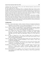
Fig. 11. The simulation results of the toggle mechanism. (‘─’desired curve; ‘ ’actual
trajectory (without friction), ‘ ’actual trajectory (with friction and
0.3
r
f = )) (a) Response
trajectories of the Lagrange multiplier
C
λ
. (b) Response trajectories of the constraint force
1
f
. (c) Response trajectories of the constraint force
2
f
. (d) Response trajectories of the
constraint force
3
f
Force/Motion Sliding Mode Control of Three Typical Mechanisms
305
7. References
[1] Fung, R. F., “Dynamic Analysis of the Flexible Connecting Rod of a Slider-Crank
Mechanism,” ASME Journal of Vibration and Acoustic, Vol. 118, No. 4, pp. 687-
689(1996).
[2] Fung, R. F., and Chen, H. H., “Steady-State Response of the Flexible Connecting Rod of a
Slider-Crank Mechanism with Time-Dependent Boundary Condition,” Journal of
Sound and Vibration, Vol. 199, No. 2, pp. 237-251(1997).
[3] Fung, R. F., “Dynamic Response of the Flexible Connecting Rod of a Slider-Crank
Mechanism with Time-Dependent Boundary Effect,” Computer & Structure, Vol. 63,
No. 1, pp. 79-90(1997).
[4] Fung, R. F., Huang, J. S., Chien, C. C., and Wang, Y. C., “Design and Application of a
Continuous Repetitive Controller for Rotating Mechanisms,” International Journal of
Mechanical Sciences, Vol. 42, pp. 1805-1819(2000).
[5] Lin, F. J., Fung, R. F., and Lin Y. S., “Adaptive Control of Slider-Crank Mechanism
Motion: Simulations and Experiments,” International Journal of Systems Science, Vol.
28, No. 12, pp. 1227-1238(1997).
[6] Lin, F. J., Lin, Y. S. and Chiu, S. L., “Slider-Crank Mechanism Control using Adaptive
Computed Torque Technique,” Proceedings of the IEE Control Theory Application, Vol.
145, No. 3, pp. 364-376(1998).
[7] Lin, F. J., Fung, R. F., Lin, H. H., and Hong, C. M., “A Supervisory Fuzzy Neural
Network Controller for Slider-Crank Mechanism,” Proceedings of the IEEE Control
Applications Conferences, pp. 1710-1715(1999).
[8] Utkin, V. I., Sliding Modes and Their Applications, Mir: Moscow (1978).
[9] Utkin, V. I., “Discontinuous Control System: State of the Art in Theory and Application,”
Preprint 10
th
IFAC World Congress, Vol. 1, pp. 75(1987).
[10] Compere, M. D. and Longoria, R. G., “Combined DAE and Sliding Mode Control
Methods for Simulation of Constrained Mechanical System,” ASME Journal of
Dynamic System, Measurement, and Control, Vol. 122, pp. 691-698(2000).
[11] Su, C. Y., Leung, T. P., and Zhou, Q. J., “Force/Motion Control of Constrained Robots
Using Sliding Mode,” IEEE Transactions on Automatic Control, Vol. 37, No. 5, pp.
668-672(1992).
[12] Grabbe, M. T., and Bridges, M. M., “Comments on “Force/Motion Control of
Constrained Robots Using Sliding Mode”,” IEEE Transactions on Automatic Control,
Vol. 39, No. 1, pp. 179(1994).
[13] Slotine, J. J. E. and Li, W., Applied Nonlinear Control. Englewood Cliffs, NJ: Prentice-Hall
(1991).
[14] Lian, K. Y. and Lin, C. R., “Sliding Mode Motion/Force Control of Constrained Robots,”
IEEE Transactions on Automatic Control, Vol. 43, No. 8, pp. 1101-1103(1998).
[15] Dixon, W. E. and Zergeroglu, E., “Comments on “Sliding Mode Motion/Force Control
of Constrained Robots”,” IEEE Transactions on Automatic Control, Vol. 45, No. 8, pp.
1576(2000).
[16] Fung, R. F., Shue, L. C, “Regulation of a Flexible Slider–Crank Mechanism by
Lyapunov's Direct Method,” Mechatronics, Vol. 12, pp. 503-509(2002).
[17] Fung, R. F., Sun, J. H, “Tracking Control of the Flexible Slider-Crank Mechanism System
Under Impact,” Journal of Sound and Vibration, Vol. 255, pp. 337-355(2002).
Sliding Mode Control
306
[18] McClamroch, N. H., and Wang, D. W., “Feedback Stabilization and Tracking of
Constrained Robots,” IEEE Transactions on Automatic Control, Vol. 33, No. 5, pp. 419-
426(1988).
[19] Fung, R. F., Lin, F. J., Huang, J. S., and Wang, Y. C., “Application of Sliding Mode
Control with A Low Pass Filter to the Constantly Rotating Slider-Crank
Mechanism,” The Japan Society of Mechanical Engineering, Series C, Vol. 40, No. 4, pp.
717-722(1997).
[20] Parviz, E. N., Computer-Aided Analysis of Mechanical System. Prentice-Hall, Englewood
Cliffs NJ (1988).
[21] Fung, R. F. and Chen, K. W., “Constant Speed Control of the Quick-return Mechanism,”
The Japan Society of Mechanical Engineering, Series C, Vol. 40, No. 3, pp. 454-
461(1997).
[22] Fung, R. F. and Yang, R. T., “Motion control of an electrohydraulic actuated toggle
mechanism,” Mechatronics, Vol. 11, pp. 939-946(2001).
[23] Fung, R. F., Wu, J. W. and Chen, D. S., “A variable structure control toggle mechanism
driven by a linear synchronous motor with joint coulomb friction,” Journal of sound
and vibration, Vol. 274, No. 4, pp. 741-753(2001).
[24] Slotine, J. J. E. and Sastry, S. S., “Tracking control of nonlinear system using sliding
surface with application to robot manipulators,” International journal of control, Vol.
38, pp. 465-492(1983).
16
Automatic Space Rendezvous and Docking
Using Second Order Sliding Mode Control
Christian Tournes
1
, Yuri Shtessel
2
and David Foreman
3
2
University of Alabama Huntsville
1,3
Davidson Technologies Inc
USA
1. Introduction
This chapter presents a Higher Order Sliding Mode (HOSM) Control for automatic docking
between two space vehicles. The problem considered requires controlling the vehicles’
relative position and relative attitude. This type of problem is generally addressed using
optimal control techniques that are, unfortunately, not robust. The combination of optimum
control and Higher Order Sliding Mode Control provides quasi-optimal robust solutions.
Control of attitude includes a receiver vehicle passive mode option where the pursuing
vehicle controls the relative attitude using the active pixels of a camera viewing a network of
lights placed on the receiving vehicle, which by sharing considerable commonality with
manual operations allows possible human involvement in the docking process.
2. Problem description
The complexity of satellite formation and automatic space docking arises from the
formulation of Wilshire equations. These equations are nonlinear and exhibit coupling of
normal and longitudinal motions. The problem is compounded by the characteristics of the
on/off thrusters used. Typical solutions to the problem involve application of optimal
control. The problem with optimal control is that it is not robust and it only works well
when a perfectly accurate dynamical model is used. This subject has been investigated
extensively by the research community (Wang, 1999), (Tournes, 2007). Since this is a
navigation and control problem involving two bodies, one question is how to obtain the
measurements to be used. Of course a data link from the receiving vehicle to inform the
pursuer about its state can be used, whereby the pursuer receives the current position
velocity and attitude state of the receiving vehicle. One could also mount distance
measurement equipment on the vehicles such as a Lidar to provide accurate range and
range rate measurements. The exchange of attitude represents a larger challenge, as the
relative motion will be the difference of the measurements/estimations by separate Inertial
Measurement Units (IMU) of their attitude. Such a difference will contain the drift and the
noise of two IMUs.
The transversal aspect of this chapter presents lateral and longitudinal guidance algorithms,
based on measurements of range and range rate without regard to the source of these
Sliding Mode Control
308
measurements which could be provided by a Lidar system
(Tournes, 2007) or interpreted
from visible cues using a pattern of reference lights.
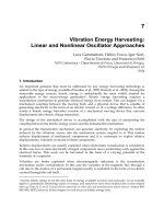
Fig. 1. Notional vehicle.
The attitude aspect presents a workable solution that does not require any reporting by the
receiving unit and is based on a pattern of reference lights, that when viewed by the pursuer
would allow the latter to evaluate the relative attitude orientation error. The quaternion
representing the relative attitude is estimated in real time by a nonlinear curvefit algorithm
and is used as the feedback of a second order sliding mode attitude control algorithm.
For simulation purposes, we assumed the pursuing vehicle (as shown in Fig. 1) to be similar
in characteristics to ESA’s Automated Transfer Vehicle (ESA 2006). Its initial mass is 10000
kg. It is equipped with a main / sustainer orientable thruster providing 4000 N thrust.
Twenty small thrusters of 500 N are used by pairs to steer roll, pitch, and yaw attitude as
well as lateral and normal motion. Regarding axial dynamics, we assume that several axial
thrusters could be used to achieve axial deceleration. We assume that using all of them
would provide a “maximum” braking; using half would provide a “medium” breaking; and
using a quarter would provide “small” braking. A major goal in the study was to obtain
extremely small velocity, position and attitude errors at the docking interface.
3. Governing equations and problem formulation
Equations governing the relative motion of the pursuer with respect to the pursued vehicle
are along in-track, out of plane and normal axis represented by Wilshire equations
(Chobotov, 2002).
()
2( )
sv T
sv T
sv
m
=
+
=
++ × + ×+ × ×
=+ =
rrρ
rrρωρωρωωρ
F
rg g+Γ
ρ = Γ + f(t)
(1)
Where
,,
sv T
rrρ
represent respectively the space vehicle position pursued vehicle position
and relative position vectors;
,
g
Γ
are the thrust and gravity accelerations.
Automatic Space Rendezvous and Docking using Second Order Sliding Mode Control
309
y
x
z
sv
target
ρ
ω
Fig. 2. System of axes used.
3.1 Translational dynamics
The system of axes used is shown in Fig. 2. Equation (1) is linearized, assuming that the
thrust
F is aligned with the pursuer longitudinal axis. Expressing the three components of
gravity vector
g as function of the pursuer position vector, one obtains
2
3
3
2
32
(.) ; (.) 2
(.) ; (.)
(.) ; (.) 2
T
x
xx
y
yy
z
T
zz
F
x
xf f z z x
m
r
F
y
yf f
m
r
F
zr
zf f x x z
m
rr
μωωω
μ
μ
μ
ωωω
=+ =−+++
=+ =−
+
=+ =− +−−+
(2)
Where
x, y, z are relative coordinates;
ω
is a rotational speed of a frame connected to the
pursued vehicle, μ represents the gravitational constant. Functions:
(.)
x
f
,
(.)
y
f
, (.)
z
f
represent the effects in Eq. (1) other than caused by thrust and are treated as disturbances.
They are smooth functions which tend to zero as the vehicles get closer. When variable
attitude mode is in effect, Eq. (2) is generalized to a form
22 2
1 1 (.); 1 (.); (.)
yzxx zyy zz
xfyfzf
δδδ δδ δ
=Γ − − + =Γ − + =Γ +
(3)
Here, FmΓ= ; F (the magnitude of the thrust) can take three discrete values, the vehicle
mass m varies slowly with time,
x
δ
can take discrete values 1,-0, 1. Pursuer pitch and yaw
attitude angles are defined as ()
z
asin
θ
δ
= and
2
(1 ,)
x
yy
atan2
ψ
δδδ
=−respectively.
When fixed attitude mode is in effect, Eq. (2) is written as:
{} {} {}
(.) ; 1,0,1 ; (.) ; 1,0,1 ; (.) ; 1,0,1
zzz yyy xxx
FFF
zf u u yf u u xf u u
mmm
=+ =− =+ =− =+ =−
(4)
3.2 Attitude dynamics
The body attitude is represented by quaternion
(.)
bod
y
Q
the dynamics of which is governed by
Sliding Mode Control
310
(.) (.)
0
0
1
0
2
0
bod
y
bod
y
pqrr
prrq
qrr p
rr q p
⎡⎤
⎢⎥
−−
⎢⎥
=−
⎢⎥
−−
⎢⎥
−−
⎣⎦
(5)
Where (.) represents some non rotating reference, i.e. Earth Centered Inertial and Where p, q,
rr represent the body rates expressed in the body frame. An alternate notation, using
quaternion multiplication (Kuipers, 1999) is:
(.) (.)
body body
=QQΩ
The dynamics p, q, rr are governed by
11
2
()
()
ppp
qcgqq
q
c
gq
rr
l
rF
p
qxxF
rr
xxF
δ
δ
δ
δ
δ
−−
⎡
⎤
⎢
⎥
⎡⎤
⎢
⎥
⎢⎥
==−×+ −
⎢
⎥
⎢⎥
⎢
⎥
⎢⎥
−−
⎣⎦
⎢
⎥
⎣
⎦
Ω I Ω II
(6)
Where I represent the vehicle matrix of inertia,
Ω the rotation matrix in body axes and
,,,, ,,,
pqp q
c
gpq
rr
FFrxx
δ
δδ
represent respectively roll, pitch/yaw thruster maximum force, roll
thrusters radial position, pitch/yaw thruster axial position, and corresponding normalized
control amplitudes in roll, pitch and yaw.
3.3 Problem formulation
3.3.1 Lateral control: The control must steer the vehicle position to the prescribed orbital
plane and orbit altitude. For that matter during the initial rendezvous, out-of-plane and
relative orbit positions with respect to pursued vehicle are calculated at the onset of the
maneuver. The HOSM lateral trajectory control calculates required acceleration to follow the
desired approach profile and calculates the required body attitude represented by
quaternion
(.)
*
bod
y
Q . During subsequent drift, braking and final docking phases the pursuer
is maintained in the orbital plane and at the correct altitude by means of on-off HOSM
control applied by the corresponding thrusters.
3.3.2 Longitudinal control: During initial rendezvous the pursuer accelerates using the main
thrust/sustainer. Corresponding thrust is shut down when the pursuer is in the orbital
plane, has attained the pursued vehicle’s orbit altitude and desired closing rate. During the
drift segment no longitudinal control is applied. The braking segment begins at a range
function of the range rate. Following coast, braking is applied until reaching the terminal
sliding mode condition. On-off deceleration pulses are then commanded by the HOSM
longitudinal control.
3.3.3 Attitude control: During the initial rendezvous, continuous HOSM controls the
attitude such that
(.) (.)
*
bod
y
bod
y
where
(.)
bod
y
Q
represents current body attitude. During
following segments the pursuing vehicle regulates its body attitude so that
(.) (.)
#
bod
y
bod
y
where
(.)
#
bod
y
Q
represents the attitude of the pursued vehicle.
Automatic Space Rendezvous and Docking using Second Order Sliding Mode Control
311
4. Why higher order sliding mode control
HOSM control is an emerging (less than 10 years old) control technique (Shtessel, 2003),
(Shkolnikov, 2000), (Shtessel, 2000), (Shkolnikov, 2005), (Tournes, 2006), (Shtessel, 2010)
which represents a game changer. It should not be confused with first order sliding mode
control which has been used for the last 30 years. Its power resides in four mathematically
demonstrated properties:
1.
Insensitivity to matched disturbances: Consider a system of relative degree n, with its
output tracking error dynamics represented as:
()
(,)
n
x
f
xt u
=
− (7)
where
(,)fxt represents some unknown disturbance. A convergence function
(1)
(,, )
n
uCxxx
−
=
is selected so that the output tracking error
x
in Eq. (7) and its
consecutive derivatives up to degree 1n
−
converge to zero in finite time in the presence of
the disturbance
(,)fxt provided that
(,)
f
xt M<
is bounded. In this application, such a
bound exists (Chobotov, 2002), (Wang, 1999). This property of HOSM control is inherited
from classical sliding mode control (SMC). Being implemented in discrete time, the output
tracking error is not driven to precisely zero but is ultimate bounded in the sliding mode
with sliding accuracy proportional to the k
ith
power of time increment t
Δ
. This property
makes HOSM an enhanced-accuracy robust control technique applicable to controllers and
to observer design.
2.
Dynamical collapse: Unlike traditional control techniques that seek asymptotic
convergence, HOSM achieves finite time convergence in systems with arbitrary relative
degree, just as classical SMC achieves the same result for the system with relative
degree one. This is much more than an academic distinction; it means that when the
sliding mode is reached the effective transfer function of inner loops with relative
degree greater than one becomes an identity.
3.
Continuous / smooth guidance laws: HOSM controllers can yield continuous and even
smooth controls that are applicable in multiple-loop integrated guidance/autopilot
control laws.
4.
Continuous / Discontinuous actuators: HOSM techniques are nonlinear robust control
techniques. When discontinuous actuators such as on-off thrusters must be used, all
linear control laws require a re-design into a discontinuous control law that
approximates the effects of the initial control law. HOSM design produces directly,
when need arises, a discrete pulse width modulated control law that achieves the same
level of accuracy as a linear control law.
5. Docking strategy
It is assumed in Fig. 3 that the automatic docking starts at a relatively large distance (>40-50
km). The pursuer, during Initial Rendezvous manages using its main thrust / sustainer to get
in a coplanar circular orbit with altitude equal to that of the receiving vehicle, but with a
slightly higher longitudinal velocity. Maintaining this altitude will require infrequent
thruster firings by the pursuer. Alternately, one could place the pursuer on a circular
coplanar orbit consistent with its longitudinal velocity and design the control law to track
the orbit associated to its current velocity which “in time” will end up being the same as the
Sliding Mode Control
312
Initial rendezvous
Drift segment
Final docking
Fig. 3. Docking strategy.
pursued vehicle altitude. During the initial rendezvous, the pursuing vehicle is set to the
desired drift velocity relative to the pursued vehicle. This maneuver is represented by
trajectory 0-1-2 in the phase portrait of Fig. 4. During this initial segment, a varying attitude
mode is applied. The transition from variable attitude to fixed attitude takes place when the
normal and out-of plane errors become lower than a prescribed threshold defined as
2222
1( ); 1 3VyzyzV
ε
=+++ <
(9)
x
2
3
4
5
(
Lar
g
e thrust
)
Slidin
g
surface S3
dri
ft
1
06
Note SW3 calculated assuming
thrust applied 15% of time
(
Medium thrust
)
(
Small thrust
)
Fig. 4. Longitudinal control strategy.
During the drift segment, normal and lateral control is applied to keep the pursuer vehicle
at the prescribed altitude and in the prescribed plane. The drift motion (2-3) begins with
Automatic Space Rendezvous and Docking using Second Order Sliding Mode Control
313
222222
();Vxyzxyz V
ε
=
+++++ <
(10)
The end of the drift segment is calculated using Pontyagyn’s Principle of Maximum. Three
switching surfaces are defined as:
222
12 3
() () () () () ()
1;2;3
222
sign x x m t sign x x m t sign x x m t
SW x SW x SW x
FF F
α
=+ =+ =+
(11)
Large, medium, or small thrust is applied as thresholds 1, 2, 3SW SW SW are reached
depending on the braking strategy used and this thrust is applied until the distance from the
terminal switching surface becomes small enough. At that point, the terminal thrust is shut
down. The termination of the decelerating maneuver is governed by
2; 2
xx
xx
σ
σε
=+ >
(12)
Once (12) is satisfied, terminal docking begins: radial and out-of-plane errors are almost null
and the only disturbance left is radial with a magnitude
(.) 2
z
f
x
ω
=
−
and this has already
been greatly reduced by previous in-track braking.
6. HOSM design of the relative navigation
6.1 Normal / Lateral control during initial rendezvous
During the initial phase of the rendezvous, the pursuing vehicle is steered by the continuous
orientation of its main thruster/sustainer. We select the relative normal / lateral positions as
the sliding variables. Given that the ultimate objective of this initial rendezvous is to set the
pursuing vehicle in an orbit coplanar to the pursued vehicle’s orbit and at the same altitude,
we define
(.)
*( ) ;(.) ,z t radial out o
fp
lane
=
to be a profile joining initial pursuer vehicle with
its terminal objective, this profile is designed to be terminally tangent to pursued vehicle
orbit. The initial rendezvous objective is thus, to steer the pursuer trajectory so
that
(.)
() *()zt z t→ . Sliding variable is chosen as:
(.) (.) (.)
*zz
σ
=
− (13)
Applying the relative degree procedure, we differentiate twice the sliding variable before
the control appears, with Eqs. (4, 13) we obtain a dynamics of sliding variable of relative
degree two.
(.) (.)
(.)
(.) (.) (.) (.)
;(.) ,
(.);
dbu z
y
F
dzf b
m
σ
=
−
=− =
(14)
Consider sliding variable dynamics given by a system with a relative degree two.
(,,) () , () 0htktukt
δ
σ
σσ
=
+>
(15)
In the considered case, the controls are continuous. Define auxiliary sliding surfaces
(.)
s as
dynamical sliding manifolds
Sliding Mode Control
314
1/2
(.) (.) (.) (.)
(.) (.) (.)
()
0,0
ssign
s
σ
ϖσ σ
σσ
=+
→⇒ →
(16)
As the sliding manifolds are relative degree 1 with respect to the system, the controller is
now relative degree 1 with respect to the sliding manifold. The corresponding Super-Twist
controllers
are given by:
[]
1/2
(.) (.) (.)
0
(() ()
0.5,0.5
(.)
t
Limit si
g
nsi
g
nd
usss
α
βτ
=− −
−
∫
(17)
Where the Limit [,] is imposed because the relative attitude with respect to the trajectory
must be bounded such as to leave enough longitudinal control authority to steer the
longitudinal relative motion.
6.2 Normal / Lateral control during fixed attitude mode
After reaching the prescribed altitude and the prescribed orbital plane, normal/lateral on-
off thrusters are used to keep the pursuing vehicle at the proper altitude and in the orbital
plane.
With
()
mM
kktk<< and (,,)htL
σσ
≤
; it is shown (Edwards, 1998), (Utkin, 1999), (Levant,
2001), (Shtessel, 2003), (Shkolnikov, 2000), (Shtessel, 2000) that a sliding variable
σ
given by
(10) is stabilized at zero altogether with its derivative
σ
in finite time by means of the
SOSM controller
0.5
( ( )), 0, 0usign sign
ρσλσ σλ ρ
=
−⋅ + > >
(18)
where
()
2
0.5 /
M
Lk
ρλ
>+ . This controller is called a second order sliding mode controller with
prescribed convergence law. It is worth noting that the high frequency switching SOSM
controller (18) achieves the finite time stabilization of
σ
and
σ
at zero in the presence of a
bounded disturbance
(,,)ht
σσ
.
Controller (18) yields on-off control that can be applied directly to the on-off thrusters. Here
we choose
8/secrad
λ
= , and
2
0.1 /ms
ρ
= is imposed by the acceleration achieved by the
on-off thrusters.
6.3 Simulation
The Six Degrees of Freedom simulation was ran in Earth Centered Inertial Coordinates over
rotating spherical Earth
1
. Attitude motion was calculated using Quaternions representing
the body attitude with respect to ECI frame
2
. The simulation was calculated in normalized
units with unit of length being the equatorial radius, the unit of velocity the circular velocity
at the surface level, and the time unit the ratio of previous quantities. The results are
presented in SI units and the gains used in normalized units converted to SI units.
1
The simulation could be easily extended to work over oblate Earth. However since the problem is a
problem of relative motion, this easy extension was not considered
2
The problem to solve is a problem of relative attitude, and for that matter any other reference could
have been chosen such as North East Down.
Automatic Space Rendezvous and Docking using Second Order Sliding Mode Control
315
Integration step used was 10
-6
normalized time units that is about 0.000806 sec. The
integrations were performed using Runge-Kutta 4 algorithm build in the Vissim simulation
software.
Normal motion
Time sec
0
200 400 600 800 1000 1200 1400 1600 1800 2000
Position & velocity errors
-1.0
5
0
.5
1.0
1.5
2.0
Normal position km
Norm al velocity m/s
Fig. 5. Normal position and velocity error.
Normal motion
Time sec
0
200 400 600 800 1000 1200 1400 1600 1800 2000
Position & velocity erro rs
-1.0
5
0
.5
1.0
1.5
2.0
Normal position km
Norm al velocity m/s
Fig. 6. Vehicle relative pitch attitude error.
Sliding Mode Control
316
The results Fig. 5 show that after the initial rendezvous normal/lateral distances to the
receiving vehicle’s orbit are kept within millimeters, millimeters /sec. Figure 6. depicts the
corresponding vehicle attitude.
Thrusters commanded acceleration
Tim e s ec
0
200 400 600 800 1000 1200 1400 1600 1800 2000
low trusters (gs)
015
010
005
0
.005
.010
.015
Commanded lateral acceleration
Commanded Normal acceleration
Fig. 7. Activity of the small thrusters.
The result Fig. 7 exhibits thruster commands during an important interval of activity in the
segment 114-930 sec. The interval 114-537 corresponds to the drift segment during which the
pursuing vehicle is at the same altitude that the pursued vehicle but has larger velocity by
approximately 40 m/s. The interval 537-936 records deceleration to a much smaller
longitudinal relative velocity. From there, as the longitudinal velocity is constantly reduced,
the firing of normal thrusters becomes more and more infrequent. Conversely the activity of
transversal thrusts reduces much more rapidly as this error is driven to zero.
6.3 Longitudinal control during terminal sliding mode phase
The prescribed longitudinal relative motion is defined by sliding variable
Figure 6. displays the corresponding vehicle normal and lateral (out-of-plane) thrusters’
activity.
x
xcx
σ
=
+
(20)
When the longitudinal sliding surface is reached (when
0
x
σ
≈
), this forces the longitudinal
velocity to reduce as the range becomes smaller. Using this surface the pulse width
controller is given by
12
0
()
(); ()
() (1 ,) 0.5 (1,)
(,) ,
t
xxx xxx
wAsign Bsigndu w
PWM
PWM u DeadBand u Triangle
Triangle A f triangular wave amplitude A frequency f
σσ σ τ
νε
=− − =
=−++
=
==
∫
(21)
Automatic Space Rendezvous and Docking using Second Order Sliding Mode Control
317
6.4 Longitudinal breaking strategies and gates
Several control strategies have been analyzed which use braking maneuvers of different
intensity and duration. We present hereafter the medium breaking strategy.
Fig. 8. Longitudinal control strategy 2 medium breaking.
Longitudinal control starts at point 1, the beginning of initial rendezvous. The pursuing
vehicle accelerates using the main thruster / sustainer until point 2 when the relative
prescribed closing velocity is reached. This point is selected such that a 15% duty cycle of
small thruster deceleration would be required to steer the relative position and velocity
approximately to zero. It is followed by a drift segment until reaching the second breaking
curve at point 3, represented by a medium breaking stategy biased by some positive range.
The medium deceleration is applied from 3-5 until reaching the sliding surface. From 5-6 the
longitudinal motion is governed by the linear manifold Eq. (12).
Results in Fig 9 show the variation of longitudinal range and range rate as functions of time.
One can note that after significant initial variations in range and range rate, their values
decrease asymptotically after reaching the sliding surface at t=914.
Longitudinal control
Time s ec
0
500 1000 1500 2000 2500 3000 3500 4000 4500 5000
Position and velocity errors
-40
-20
0
20
40
Range km
Range rate m/s
Fig. 9. Longitudinal control.
Sliding Mode Control
318
Results Fig. 10 show the absence of longitudinal control during the “drift” segment and also
the continuous application of the “medium” deceleration from 700-796 sec. Results in Fig.10
show the pattern of longitudinal thrust. Starting on the left, one can note the sustainer thrust
followed by the drift segment where no longitudinal thrust is applied, the deceleration
pulse, then the deceleration segment where braking thrust is applied continuously;
Longitudinal actuators
Time s ec
0
500 1000 1500 2000 2500 3000 3500 4000 4500 5000
Longitudinal thrust (gs)
050
025
0
.025
.050
Commanded longitudinal acceleration
Fig. 10. Longitudinal thruster activity.
Results Fig. 10 also show the absence of longitudinal control during the “drift” segment and
the continuous application of “medium” deceleration from 700-796 sec. Results in Fig. 10
show the pattern of longitudinal thrust. Starting on the left, one can note the sustainer thrust
followed by the drift segment where no longitudinal thrust is applied, the deceleration
pulse, then the deceleration segment where braking thrust is applied continuously;
thereafter, the firing becomes sparser and the durations of the thrust pulses smaller, and
reaches ”soft kiss” conditions with range and range rate in the sub-millimeter and
millimeter / sec. It is possible to make the docking faster by modifying parameter c in
Eq. (20) and to interrupt it sooner as docking tolerances are reached. Another factor that
may be considered in the automatic docking is the incorporation of cold gas thrusters to
provide small and clean propulsive increments for final docking.
Three gateways are designed to check that the automatic docking is on track; equivalently,
that provided the interceptor position is within the gate, docking can be pursued safely;
specifically, that the margin of error they define can be corrected safely with available
control authority.
For that matter we are going to present the gates from final to initial.
The third gateway is defined at the beginning of the deceleration The outer range is the
minimum range such that if small thrusters are applied continously, the deceleration will
achieve a zero velocity and distance from the receiving station. The deceleration must begin
at the latest when intersecting the outside elliptical contour. The inner contour represents
the minimum time for driving the longitudinal sliding variable to zero. The terminal
deceleration in sliding mode must be initiated before reaching the inner contour.
At point 3 of Fig. 11, the pursuing vehicle begins medium braking, segment 3-5. Point 4 is at
the intersection with the contour where there is enough stopping power to overcome the
disturbances and stop at the origin using the small break. The breaking maneuver with
small break must begin at the latest at point 4. The point 5 is designed to be on the
intersection of the sliding manifold Eq. (12), with the small braking biased contour.
Automatic Space Rendezvous and Docking using Second Order Sliding Mode Control
319
Evidently, the point 5 must be outside the inner elliptical contour that defines the minimum
time needed to drive the terminal sliding surface to the origin.
Fig. 11. Third gate.
The second gate Fig. 12 defines the drift segment. It begins at point 2; the intersection of the
drift segment with SW3 and it ends at point 3 the beginning of the braking maneuver on
biased SW5.
Fig. 12. Second gate.
Sliding Mode Control
320
The first gate (Fig. 13) defines the initial contour where the interceptor must be in the phase
plane to intersect the small partial thrust SW3 with a viable drift velocity value and suffcient
drift time. In any case the initial point 1 must be above SW3 and there is some latitude
regarding the initial velocity and range.
Fig. 13. First gate.
7. Use of active bitmap pixels to control relative attitude
Regulation of pursuer attitude for automated docking can be broken into two functional
segments. While the objects are far apart, the pursuer’s attitude is controlled to align its axial
direction with the relative line of sight and to place its normal direction in the orbital plane.
Control during this segment has been done many times and is not the subject of this
discussion. When the objects are very close, and before docking can occur, the pursuer must
align its mating surface with that of the pursued vessel. In this section, we discuss one
practical method that this alignment can be performed efficiently, reliably and
automatically.
Any geometry will do, but suppose that both mating surfaces are circular and that the target
object is fitted with a series of detectable objects (i.e. lights) equally spaced around the
mating surface. Suppose further that the pursuer is fitted with an array of suitable detectors
which we shall call the Focal Plane Array (FPA) and that this FPA can be considered to lie in
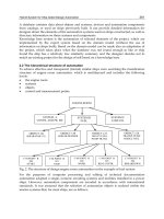
the center of its mating surface. As described in figure 14, if the surfaces are ready for
docking, the pursuer will perceive a circular ring of lights in the center of the FPA. If the
surfaces are offset, then the ring will be offset on the FPA. If the surfaces are misaligned, the
ring will be elliptical rather than circular. The apparent size of this perceived ring of lights
will indicate separation distance; the center will indicate normal and lateral error; the
eccentricity of the ellipse will indicate the degree of angular error; and the orientation of the
ellipse will indicate the relative axis about which the pursuer must rotate for successful
docking. Although we will not address relative roll in this chapter, if one of the lights is
Automatic Space Rendezvous and Docking using Second Order Sliding Mode Control
321
distinct from the others, a roll error could also be deduced. This is nearly equivalent to the
information a human pilot would use to accomplish the same task.
Automated control of attitude for docking is thus reduced to two necessary tasks. First,
information from the FPA must be interpreted (in the presence of noise) to yield a real-time
measure of attitude error. Second, that error must be used to correctly orient the vehicle. We
will apply a nonlinear least-squares curvefit and multidimensional search to the corrupted
pattern of lights in order to estimate the equation of the perceived ellipse. The relative
magnitude and orientation of the semi-major and semi-minor axes of this ellipse are used to
generate a necessary angle of rotation and the unit vector we must rotate about,
respectively. The relative degree approach will be used to generate a second-order sliding
mode controller of the type described in (Levant, 2003). Finally, these methods will be
implemented and tested using simulation.
c
′
d
′
a
a
′′
o
b
b
′′
o
′
Reveals a lateral/normal error
′′
δψ
What we expected
to see
b
′
a
′
b
′′′
a
′′′
d
′′
c
What we see
Fig. 14. Use of light patterns to extract relative position and attitude.
7.1 Mathematical background: Quaternions
The idea of relating two oriented surfaces (equivalently, two reference frames) by a single
rotation about a specified axis is precisely the motivation behind the concept of quaternions.
Since many readers will not be familiar with quaternions, we introduce a few important
concepts here. Those wishing to understand quaternions in greater depth are referred to Dr.
Kuipers’ excellent book (Kuipers, 1999) on the subject.
Let us describe the relationship between two right-hand coordinate systems as a single
rotation about a specified axis. Let us package this description into a 4-vector as follows:
[]
cos
ˆ
ˆ
sin
()
thema
g
nitudeo
f
rotation
the unit vector torotate about
η
η
η
=
⎡⎤
⎡⎤
==
⎢⎥
⎢⎥
=
⎣⎦
⎣⎦
Q
u
u
0
q
q
(22)
It is easily verified that this construct has (Euclidian) norm 1. If we define multiplication of
these objects in a particular way, they exhibit several useful traits. Define:
Sliding Mode Control
322
00 0 0
PQ=p q -p q+p q+q p+p×qi (23)
The following four useful and remarkable properties hold:
1.
For any quaternion Q,
[]
00
1000
t
⎡⎤⎡⎤
===
⎢⎥⎢⎥
−
⎣⎦⎣⎦
**
QQ Q Q
and this is the
quaternion relating any coordinate frame to itself.
2.
Given a vector v in the initial reference frame, the vector part of
*
0
⎡⎤
⎢⎥
⎣⎦
v
is the
equivalent vector in the rotated frame.
3.
Given quaternion P relating frame 1 to frame 2 and quaternion Q relating frame 2 to
frame 3, the product QP is the quaternion relating 1 to frame 3.
4.
If Q is the quaternion relating frame 1 to frame 2 and
⎡
⎤
⎢
⎥
⎢
⎥
⎢
⎥
⎣
⎦
pp
Ω =qq
rr
represents the turning
rate of frame 1 relative to frame 2 (i.e. the body rates) then
0
⎡
⎤
=
⎢
⎥
⎣
⎦
Ω
7.2 Attitude error from FPA measurements
In this exercise we are assuming that the pursuer’s on-board sensor is the only source of
attitude feedback. Specifically, this information takes the form of a set of Cartesian positions
on the FPA corresponding to the location of the docking lights; with the detectors on the
FPA working in the same way as rods on a human retina. Our challenge is to interpret, from
this list of positions, the relative orientation of the pursuer and target docking surfaces.
As discussed in the introduction, if the docking surfaces are not perfectly adjusted, a circular
pattern of indistinguishable lights (Fig. 15a) will appear as an offset ellipse (15b).
Fig. 15a. Circular pattern of docking lights.
Lateral and longitudinal guidance was described earlier in this chaper; thus we are only
concerned that the pursuer’s attitude be modified such that the percieved ellipse become
circular. We proceed in two steps: first determine the equation of the ellipse that most nearly
fits the measurements; then compute attitude error from this equation.
Automatic Space Rendezvous and Docking using Second Order Sliding Mode Control
323
Fig. 15b. Docking lights as seen by pursuer.
The formal equation of an offset, rotated ellipse is:
(
)
()
(
)
(
)
()
(
)
22
22
cos sin sin cos
1
cc cc
yz
yy zz yy zz
ll
φφ φφ
−+− −−+−
+
=
(24)
To perform least-squares curvefit from a set of measured points (x,z), define a function:
()
()
()
()
()
()
2
22
22
cos sin sin cos
1
cc cc
alllights
yz
yy zz yy zz
E
ll
φφ φφ
⎧⎫
−+− −−+−
⎪⎪
=− +
⎨⎬
⎪⎪
⎩⎭
∑
(25)
We will find a local minimum value of E with respect to the parameters
{
}
,,,,
ccyz
yzll
φ
using
the steepest descent method:
()
2
2
22
2
c
cc
c
cc
yy
y
zz
ccyz
z
E
y
yy
E
z
zz
E
ll
l
ll
EEEEE
E
yzll
l
E
ρ
φ
φφ
φ
+−
∂
⎡
⎤
∂
⎢
⎥
⎢
⎥
⎡⎤ ⎡⎤
∂
⎢
⎥
⎢⎥ ⎢⎥
∂
⎢
⎥
⎢⎥ ⎢⎥
∂
⎢
⎥
⎢⎥ ⎢⎥
=−
∂
⎢
⎥
⎢⎥ ⎢⎥
⎛⎞
⎛⎞
⎛⎞ ⎛⎞
∂∂∂∂∂
⎢
⎥
⎢⎥ ⎢⎥
++++
∂
⎜⎟ ⎜⎟
⎜⎟
⎜⎟
∂∂∂∂∂
⎢
⎥
⎢⎥ ⎢⎥
⎝⎠ ⎝⎠
⎝⎠
∂
⎝⎠
⎣⎦ ⎣⎦
⎢
⎥
∂
⎢
⎥
∂
⎣
⎦
(26)
with the ad-hoc addition that, if
EE
+
−
>
then
10
ρ
ρ
←
. This iteration is allowed to continue
until the function E converges to a constant value at which the parameters describing the
“best-fit” ellipse are established
3
.
3
The multivariate search described above requires an initial guess for each parameter. Convergence rate
is sensitive to this guess and to the initial step size ρ. Furthermore, if care is not exercised, this search
may converge to a local (and not global) minimum. An extensive discussion of multivariate search
isoutside the scope of this chapter. outside the scope of this chapter.
Sliding Mode Control
324
The magnitude of rotation necessary for the ellipse to appear circular is described by:
cos cos
l
ll a
l
ηη
=⇒=
z
zy
y
The required axis of rotation is the ellipse semi-major axis, which is described by:
ˆ
ˆˆ
cos sin
φ
φ
=+uyz (27)
The quaternion relating the pursuer’s attitude to that necessary for docking is, therefore:
1
1
cos
2
2
0
0
1
sin cos
1cos
2
2
sin sin
1
1sin
2
2
l
l
l
l
l
l
η
η
φ
φ
η
φ
φ
⎡
⎤
⎛⎞
−
⎢
⎥
⎡⎤
⎜⎟
⎝⎠
⎢
⎥
⎢⎥
⎢
⎥
⎢⎥
⎢
⎥
⎢⎥
⎢
⎥
⎢⎥
==
⎛⎞
⎢
⎥
⎢⎥
+
⎜⎟
⎢
⎥
⎢⎥
⎝⎠
⎢
⎥
⎢⎥
⎛⎞
⎢
⎥
⎢⎥
+
⎣⎦
⎜⎟
⎢
⎥
⎝⎠
⎣
⎦
z
y
z
y
z
y
Q
(28)
7.3 Derivation of the attitude control law
The relative degree approach to derivation of a control law consists of a sequence of general
steps. First, establish an approximate mathematical model for the object to be controlled. If
(as is always the case) this model is imperfect, we include an unknown “disturbance”
function into which all of the uncertainties, approximations and unknowable quantities are
swept. Second, the feedback error is defined. This error must be generated from measured
quantities and must be positive definite. In the third step, a mathematical relationship is
established between the feedback error and the actual control. This relationship is made to
fit a template equation that is well-behaved in the presence of the expected disturbance.
Finally, the relationship is solved to describe the necessary control in terms of the feedback
error, possibly other measured quantities and the disturbance, which is discarded.
Let Q represent the quaternion relating the pursuer body frame to the required attitude for
docking as computed in (24). In practice, the pursued vehicle may be rotating, but because
we derive all our information from the pattern of docking lights, the pursued vehicle’s
rotation is confounded with the pursuing vehicle’s rotation and is thus unknowable.
Therefore we shall consider the desired attitude to be an inertial frame and consider any
error resulting from this supposition to be part of the disturbance function. Further define:
p
p
rr
⎡⎤
⎢⎥
=
⎢⎥
⎢⎥
⎣⎦
Q,ω
is the vector of the pursuer’s body rates
Automatic Space Rendezvous and Docking using Second Order Sliding Mode Control
325
33x
∈I is the pursuer’s matrix of inertia, which is considered nonsingular
33
3
x
⎧
∈
⎪
⎨
∈
⎪
⎩
B
u
such that Bu represents the moment contribution of control in the body axis
The equations of state may be described as:
11−−
=+
=− × + +
1
2
QQ Δ
IIIBuΔ
ω
ωωω
(29)
For docking, we want the pursuer’s body frame to align with the desired frame; this is
equivalent to driving
[]
1000
t
→Q . Because Q has norm 1, driving the vector part to
zero will accomplish this desire. If we consider desired rotation about the body x-axis to be
zero and restrict the remaining axis of rotation to quadrants 1 and 2 (accounting for the
direction of rotation by other means) taking feedback error to be the vector part of Q results
in a positive definite function. Therefore, with obvious notation, let:
[
]
123
= Qσ (30)
ignoring disturbances and differentiating:
[
]
123
= Qω
σ
[]
11
123
123
()
−−
⎡
⎤
=+ =+−×+
⎣
⎦
QQ Q QQ Q I I I Bu
σωω ω ωω (31)
Before proceeding, we will need the following theorem:
Theorem: For quaternions
[] []
00
,
⎡
⎤⎡⎤
==
⎢
⎥⎢⎥
⎣
⎦⎣⎦
pq
PQ
pq
,
[]
{
}
000
123
123
=+
*
PPQ pqpqp (32)
Proof: from Kuipers (p.108):
[]
[]
()
()()
[]
{}
()()()
00
00
000
123
00 0 0 0
2
0000 0 0
123
123
2
000
(0)
(0)
q
−
⎡⎤
=
⎢⎥
++×
⎣⎦
⎡
⎤
+++×
⇒=
⎢
⎥
⎡
⎤
++×− −× ++×
⎢
⎥
⎣
⎦
⎣
⎦
=
+ + ×− ×− ×−××
=+
*
*
pq pq
PQ
pq qp p q
pppqqppq
PPQ
ppqqppq pp pqqppq
PPQ pqpqpppq p pq q pp ppq
ppqp
i
i
□
Define:
(
)
1/2
1,2,3 1,2,3 1,2,3 1,2,3
(,) ( )sign
ρμ
=− σ + σ σSSIGN
σσ
where ρ and μ are positive constants. (33)
It is shown [26] that the equation: ( , )
−
=S
1
,2,3 1,2,3 1,2,3
σ
σσ Δ is finite-time stable and displays
“good” transient behavior in each of its three elements so long as elements of the disturbance
Δ are bounded by the proportionality constant ρ. Substituting for the second derivative in (31):
Sliding Mode Control
326
11
123
()
−−
⎡
⎤
=+−×+
⎣
⎦
SQQ QI I IBuωωω
Pre-multiply both sides by
*
Q and apply the theorem:
[]
(
)
11
123
123
−−
⎡
⎤
=+−×+
⎣
⎦
** *
QS Q QQ Q Q I I I Buωωω
[
]
[
]
22121
00 0 0
123 0
123 123
()()
−−
⎡⎤ ⎡⎤
=+ −×+
⎣⎦ ⎣⎦
**
QS q Q q Q Q q I I q I Buωω ωω
Solve for the control u:
[]
[
]
[]
11
0
2
123 123
123
0
0
1
()
q
−−
⎧
⎫
⎪
⎪
⎡⎤
=−+−×
⎨
⎬
⎣⎦
⎪
⎪
⎩⎭
*
Q
uBI QS Q Q I I
q
ω
ω
ωω
(34)
7.4 Simulation results
In order to demonstrate this method of attitude control for automated docking, a ten-second
interval near the end of a docking mission was simulated. The initial separation is 11 m and
the closing velocity is 1 m/sec. Lateral and longitudinal control are not included in this
exercise, nor is roll attitude. Initially, the docking surfaces are misaligned by .1 radian
(~6 degrees) in the pitch direction and .25 radians(14 degrees) in yaw. Additionally, we have
initial body rates equal to .05 rad/sec away from zero in the pitch and .1 rad/sec towards
zero in yaw. Realistically, seeker error would decrease as the surfaces approach, but for
demonstration purposes, a uniformly-distributed 5% error was added to the y- and z-
positions of each docking light.
The gains ρ and μ of Eq. (33) were empirically set to 5 and 0.25, respectively; these gains
were intentionally not fine-tuned and it was observed that acceptable behavior is exhibited
when either or both of these are halved or doubled.
Results are summarized in Figs. 16 – 18.
Ellipse Characteristics
Time (sec)
0
2 4 6 8 10
40
15
.10
.35
.60
.85
1.10
1.35
1.60 semi-major length (m)
semi-minor length (m)
rotation (rad/pi)
Fig. 16. Characteristics of the curvefit ellipse.
Automatic Space Rendezvous and Docking using Second Order Sliding Mode Control
327
In Fig. 16 we observe that the (normalized) semi-major axis length is constant at unity. This
is necessary, as the apparent length (adjusting for changes in proximity) does not change
with aspect. The semi-minor axis length is initially somewhat less, but quickly converges to
one; this is an indication that the percieved ellipse becomes a percieved circle. At about the
time the semi-minor axis approaches unity, the apparent rotation of the ellipse becomes
chaotic. This is expected – as the FPA image becomes more circular, definition of the semi-
major and semi-minor axes is largely determined by noise.
Sliding Manif old
Time ( sec)
0
2 4 6 8 10
15
10
05
0
.05
.10
pitch surf ace
yaw surface
Fig. 17. Quaternion elements 2 and 3.
Euler A ngle s
Time (sec)
0
2 4 6 8 10
radians
25
20
15
10
05
0
.05
.10
.15
pitch
yaw
Fig. 18. Corresponding pitch and yaw angles.
Sliding Mode Control
328
In Fig. 17 we observe that the sliding variables are driven into a narrow band about zero in
finite time and remain within that band thereafter. Note that actual convergence to the
sliding surface occurs significantly after the quaternion axis (green line of Fig. 16) becomes
chaotic. It is apparent that the averaged reaction to extremely noisy feedback is still useful
for control. If the seeker noise was correlated in time, we might expect to see a small and
persistent error away from zero.
Euler angles are easily extracted from the quaternion elements. In Fig. 18 we see the pitch
misalignment, which started nearer to zero converge first, followed by yaw. After the
transient, both angles are constrained to within about 3 or 4 milliradians (0.2 degrees).
Speed of convergence and ultimate boundary are largely dictated by the gains ρ and μ of
Eq. (33), subject to limitations on thruster force and the need to dominate the sum of all
disturbances.
7.5 Observations
Before concluding this section, let us make some interesting and important observations
concerning the demonstrated method for automatic control of attitude for docking.
First, this automated method is very similar to the approach taken by a human pilot; rather
than assembling position and attitude information from a variety of sources, computing a
time profile and inverting the physical model to produce attitude commands, this method
“sees” that the ring of docking lights is slightly out of round and nudges the controls in
response. This not only increases confidence in the robustness of our method, but introduces
the possibility of Human Assisted Control (HAC) for docking attitude.
Second, there is no Inertial Measuring Device (IMU) input involved in this method. This
means no IMU errors, no acquisition and processing of IMU data, no synchronization of
IMUs between the pursuer and pursued and no provisioning for loss of data. All feedback is
from a single, reliable on-board source. On a related note, there is no participation required
on the part of the pursued object and no communication requirement. This is extremely
favorable because communication increases risk and always introduces delay. Delay is
extremely detrimental to sliding mode control, which is fundamentally based on high-
frequency switching.
Finally, the reader may have spotted a significant flaw in our method. When interpreting the
ring of docking lights as an ellipse on the FPA, the magnitude of rotation and the axis of
rotation can be determined, but there is no inherent way to determine the direction of
rotation. In other words, we cannot tell if the ellipse is tipped “towards” us or “away”. This
perceptive reader is correct; some other method such as Doppler ranging or a comparison of
the relative brightness on each side of the semi-major axis must be used to supply this final
bit of information. While generating the results of Figs. 16-18, we assumed that the
directionality was known and correct.
7.6 Conclusion: Attitude control
It is possible to control relative attitude by simply constructing a quaternion error function of
the pattern of lights. One must note that the algorithm process is very similar to the human
control processes in that the idea is to drive errors to zero. These solutions are enabled by the
property that sliding mode controllers are perfectly insensitive to matched disturbances. Using
this property it is possible to not represent explicitly in the design some dynamical terms of the
sliding variable dynamics and to treat them simply as disturbance terms.