VoIP Technologies Part 10 pdf
Bạn đang xem bản rút gọn của tài liệu. Xem và tải ngay bản đầy đủ của tài liệu tại đây (869.58 KB, 25 trang )
20 VOIP Technologies
Fig. 16. Measured R factor (a) and MOS (b) vs WLAN* traffic data rate for different SIR
visible; in fact, R
max
is nearly 22 Mbit/s for SIR = 6dBand<< 22 Mbit/s for SIR ≤ 1 dB,
as shown by the two upper curves, which, in the range 22 - 34 Mbit/s, assume very high
values (
≥ 70 dB). In this case, further measurements should be performed at lower data rate
to determine the corresponding values R
max
below which packet loss becomes negligible
or even null;
2. in terms of jitter, Fig. 15 shows that scenario A is rather immune even to the simultaneous
presence of AWGN interference and concurrent data traffic. In fact, the estimated jitter
curves appear very close one with another with values not higher than 12 ms, that means
quite negligible with respect to the 150 ms threshold. A different effect can instead be noted
in the wireless-wireless setup, where packet loss significantly worsens upon the increasing
of AW GN interference intensity. Also in this case, the effect of AWGN interference is clearly
visible for SIR valures equal to or lower than 1 dB;
3. Fig. 16 finally shows that at application layer the simultaneous presence of both
competitive WLAN data traffic and AWGN interference is very detrimental even with data
rate values in the range 22
− 25 Mbit/s and for any considered SIR value. The obtained
R factor highlights that “very satisfied” levels of voice quality cannot be obtained for
concurrent data rate levels higher than 22 Mbit/s.
Further tests have been performed at the same setup conditions but with different audio
codecs, i.e. the aforementioned G.723.1 and G.729. The following results have been observed:
A. In terms of packet loss, G.711 is the audio codec that provides better results. In particular,
a nearly 10% worsening of packet loss is observed for both G.723.1 and G.729 regardeless
of the considered intereference data rate.
B. G.711 is also better in terms of jitter, which, for the G.729 codec, assumes very high values,
even up to nearly 75 ms for an interference data rate equal to 35 Mbit/s.
C. The R factor is quite the same for G.723.1 and G.729 codecs, and much higher for G.711.
For instance, in the scenario B and with 25 Mbit/s of interference data rate, t he estimated
R factor is 85 for G.711 and nearly 6 7 for G.723.1 and G.729 codecs.
216
VoIP Technologies
VoIP Over WLAN: What About the Presence of Radio Interference? 21
D. Similarly, MOS is quite the same for G.723.1 and G.729 codecs, and much higher for G.711.
For instance, in the scenario B and with 25 Mbit/s of interference data rate, t he estimated
MOS is 4.3 for G.711 and nearly 3.8 for G.723.1 and G.729 codecs.
6. Conclusion
A number of experimental results have been p r esented in o rder to investigate on the
interference effects of Bluetooth signals, AWGN and WLAN competitive data traffic on IEEE
802.11g WLAN supporting VoIP applications. Cross layer measurements performed in terms
of SIR, jitter, packet loss, R factor and MOS have been carried out with the aim of analyzing
the best configurations of parameters like the interfering WLAN data rate and the measured
SIR at the receiver side. For instance, in both the analyzed scenarios, i.e. wired-wireless and
wireless-wireless WLAN, the maximum interfering WLAN data rate R
max
and the minimum
SIR, SIR
min
, values have been estimated.
It has been demonstrated that the use of VoIP over WLAN can strongly be interfered by the
presence of in-channel noise-like signals, such as AWGN, and of competitive data traffic
generated by a near operating WLAN exploiting the same frequency channel. Therefore,
parameters like SIR and WLAN interference data rate should always be carefully monitored
and, if possible, adjusted beyond or below the thresholds R
max
and SIR
min
, respectively, to be
estimated as suggested in the chapter. The use of G.711 codec is also suggested against the
simultaneous effect of both concurrent data traffic and radio interference.
Many other measurement sessions could be performed to investigate on further interference
phenomena here not considered for more conciseness. For instance, the analysis could be
extended to the study of the interference effects due to burst-like signals or real life ones. It
could also be very interesting extending the study to many other system parameters, like for
instance those c oncerning system’s quality of service.
7. References
Lin, Y. B. & Chlamtac, I. (2000). Wireless and Mobile Network Architectures, John Wiley and Sons,
ISBN 978-0-471-39492-1, New York, US.
Douskalis, B. (1999). IP Telephony: The Integration of Robust VolP Services, Prentice Hall, ISBN
978-0-13-014118-7, New Jersey, US.
IEEE Standard 802.11 (1999). Wireless LAN Medium Access Control (MAC) and Physical Layer
(PHY) Specifications, IEEE computer society.
IEEE Standard 802.15.4 (2003). Wireless Medium Access Control (MAC) and Physical Layer
(PHY) Specifications for L ow-Rate. Wireless Personal Area Networks (LR-WPANs), IEEE
computer society.
IEEE Standard 802.16 (2001). IEEE Standard for Local and Metropolitan Area Networks - Part 16:
Air Interference for Fixed Broadband Wireless Access Systems, IEEE computer society.
Garg, S. & Cappes, M. (2003). An Experimental Study of Throughput for UDP and VoIP Traffic
in IEEE 802.11b Networks, Proceedings of Wireless Communications and Networking,pgs
1748-1753, New Orleans, LA, US, March 2003.
Angrisani, L . & Vadursi, M. (2007). Cross-layer Measurements for a Comprehensive
Characterization of Wireless Networks in the Presence of Interference, IEEE Trans.
on Instrumentation and Measurement, Vol. 56, No. 4, 2007.
Wang, X. G.& Mellor, G.M. (2004). Improving VOIP application’s performance over WLAN
using a new distributed fair MAC scheme, Proceedings of Advanced Information
217
VoIP Over WLAN: What About the Presence of Radio Interference?
22 VOIP Technologies
Networking and Applications, pgs 126-131, ISBN: 0-7695-2051-0, March 2004, Fukuoka,
Japan.
Wang, W. & Li, S.C.L. (2005). Solutions to Performance Problems in VoIP Over a 802.11
Wireless LAN, IEEE Trans. on Vehicular Technology, Vol. 54, No. 1, Jan 2005, pgs
366-384.
Garg, S. & Cappes, M. (2002). On the Throughput of 802.11b Networks for VoIP, TechnicalReport
ALR-2002-012, Av aya Labs, 2002.
El-fishawy, N. A. & Zahra, M. M. & El-gamala, M. (2007). Capacity estimation of VoIP
transmission over WLAN, Proceedings of Radio Science Conference, pgs 1-11, March
2007, Cairo, Egypt.
Prasat, A. R. (1999). Performance comparison of voice over IEEE 802.11 schemes, Proceedings
of Vehicular Technology Conference, pgs 2636-2640, Vol. 5, Sept. 1999, Houston, Tx, US.
Hiraguri, T. & Ichikawa, T. & Iizuka, M. & Morikura, M. (2002). Novel Multiple Access
Protocol for Voice over IP in Wireless LAN, IEEE Int. Symp. on Computers and
Communications, pgs 517-523, ISBN: 0-7695-1671-8, July 2002, Taormina, Italy.
ITU-T Recommendation G.711 (1972). Pulse Code Modulation (PCM) of Voice Frequencies, 1972.
ITU-T Recommendation G.729 (1996). Coding of Speech at 8 kbit/s Using Conjugate-Structure
Algebraic-Code-Excited Linear Prediction (CS-ACELP), 1996.
ITU-T Recommendation G.723.1 (2006). Digital Terminal Equipments - Coding of Analogue Signals
by Methods Other Than PCM. Dual Rate Speech Coder for Multimedia Communications
Transmitting at 5.3 and 6.3 kbit/s, 2006.
ITU-T Recommendation P.800 (1996). Methods for Subjective Determination of Transmission
Quality, 1996.
Schulzrinne, H. & Casner, S. & Frederick, R. & Jacobson, V. (2003). RTP: A Transport protocol for
Real-Time Applications, RFC 3550, July 2003.
Angrisani, L. & Bertocco, M. & Fortin, D.& Sona, A. (2007). Assessing coexistence
problems of IEEE 802.11b and IEEE 802.15.4 wireless networks through cross-layer
measurements, IEEE International Instrumentation and Measurement Technology
Conference, paper n. 7326, ISBN: 1-4244-0588-2, May 2007, Warsaw, Poland.
Botta, A. & Dainotti, A. & Pescape, A. (2007). Multi-protocol and multi-platform traffic
generation and measurement, INFOCOM 2007 DEMO Session, May 2007, Anchorage,
Alaska, USA.
Bertocco, M, & Sona, A. (2006). On the power measurement via a superheterodyne spectrum
analyzer, IEEE Trans. on Instrumentation and Measurement, pgs. 1494-1501, ISSN:
0018-9456., Vol. 55, No. 5, 2006.
218
VoIP Technologies
1. Introduction
VoIP services have been considered as one of the most important services in the next
generation wireless systems. VoIP service requires the same quality of service (QoS)
requirement as constant bit rate services. For this reason, the IEEE 802.16 standard has defined
an unsolicited grant service (UGS) to guarantee the QoS. However, the UGS is inadequate
to support VoIP services with silence suppression because of the waste of radio bandwidth
in the silent-periods. In the UGS, a base station (BS) periodically allocates a maximum-size
radio bandwidth (grant) during the silent-periods even though a subscriber station (SS) does
not have a packet to transmit in the silent-periods. To solve this problem, (Lee et al., 2005)
proposed an extended real time polling service (ertPS) to support VoIP services with silence
suppression. The ertPS can manage the grant-size according to the voice activity in order to
save the radio bandwidth in silent-period. Unfortunately, the waste of radio bandwidth and
the increase of access delay can still exist when the ertPS is applied to the system because the
grant-size and grant-interval used by the ertPS cannot correspond with the packet-size and
the packet-generation-interval of the VoIP services in the application layer.
Recently, the IEEE 802.16’s Task Group m (TGm), which was approved by IEEE to develop an
amendment to IEEE 802.16 standard in 2006, published the draft evaluation methodology
document in which several kinds of VoIP speech codecs are considered such as G.711,
G.723.1, G.729, enhanced variable rate codec (EVRC), and adaptive multi-rate (AMR)
(Srinivasan, 2007). These VoIP speech codecs generate packets with different packet-size and
packet-generation-interval as shown in Table 1. However, the IEEE 802.16 standard does not
define the QoS parameter generation method, because they have focused on only medium
access control (MAC) and physical (PHY) layer. For this reason, IEEE 802.16 based systems
need the QoS parameter mapping algorithm to obtain the features of the VoIP services in
the application layer. Hong and Kwon (Hong & Kwon, 2006) proposed the QoS parameter
mapping algorithm to exploit the feature of the VoIP services in IEEE 802.16 systems which
statistically measures the peak data rate of VoIP services and calculates the QoS parameters.
However, the algorithm needs significant time to measure the VoIP traffic to perform the
statistical analysis, and the QoS parameters cannot correspond to the features of the VoIP
services when the number of samples of the VoIP traffic is not sufficient to analyze the features
of the VoIP service. To overcome these problems, this chapter designs a cross-layer QoS
parameter mapping scheme which exploits the information of the VoIP speech codec included
in the session description protocol (SDP) to generate the QoS parameters for VoIP scheduling
algorithms.
Sung-Min Oh and Jae-Hyun Kim
School of Electrical and Computer Engineering, Ajou University
Republic of Korea
VoIP Features Oriented Uplink Scheduling
Scheme in Wireless Networks
10
2 VoIP Technologies
(a) G.7xx with silence suppression (b) EVRC
(c) AMR
Fig. 1. Traffic models for various VoIP speech codecs
Moreover, this chapter proposes a new cross-layer VoIP scheduling algorithm which exploits
the QoS parameters generated by the proposed QoS parameter mapping scheme. The
conventional VoIP scheduling algorithms have been designed considering a specific VoIP
speech codec. The UGS has been designed to guarantee a QoS for G.7xx (i.e. G.711, G.723.1,
and G.729) without silence suppression, and the ertPS has been developed to support EVRC.
In particular, the ertPS is designed to compensate for the resource inefficiency of the UGS
in the silent-periods. Unfortunately, the ertPS is not an optimal VoIP scheduling algorithm
for the whole VoIP speech codecs. In the ertPS, a BS periodically allocates a minimum-size
grant to a SS every 20 msec regardless of the voice activity in the silent-period. However,
the AMR speech codec generates a packet every 160 msec in the silent-period. Thus, the
ertPS can cause the waste of radio bandwidth in the silent-period when it supports the AMR
speech codec. To overcome this inefficiency of the ertPS, Oh et al (Oh et al., 2008) proposed
a new VoIP scheduling algorithm, which is called as a hybrid VoIP (HV) algorithm in this
chapter. The HV algorithm adapts a random access scheme in the silent-period to save
radio bandwidth. However, it can suffer from an overhead occurred in the silent-period
when the EVRC is applied in the application layer. The problems of VoIP scheduling
algorithms according to the VoIP speech codecs are detailed in section 3. Consequently,
this chapter proposes the cross-layer VoIP scheduling algorithm to support all available VoIP
speech codecs. The main feature of the cross-layer VoIP scheduling algorithm is that it can
dynamically adjust the grant-interval in the silent-period according to the VoIP speech codec
applied in the application layer. By this feature, the proposed scheduling algorithm can save
radio bandwidth guaranteeing a QoS for all VoIP speech codecs in the silent-period. The
description of the proposed scheduling algorithm is presented in section 4.
2. Traffic models for various VoIP speech codecs
This section describes traffic models for various VoIP speech codecs which are presented in
Fig. 1 where each VoIP speech codec has individual features in their packet generation policy
(ITU-T-G711, 2000; ITU-T-G7231, 1996; ITU-T-G729, 2007; 3GPP2-EVRC, 2004; 3GPP-TS-26201,
2001; 3GPP-TS-26092, 2002; 3GPP-TS-26071, 1999). Fig. 1 (a) represents a traffic model for
220
VoIP Technologies
VoIP Features Oriented Uplink Scheduling Scheme in Wireless Networks 3
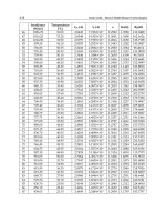
VoIP Speech Codec PS (bytes) PGI (msec)
G.711 160 20
G.723.1 19.88 30
G.729 10 10
EVRC 21.375, 10, 2 20
AMR Voice frame: 11.875, Talk-spurt: 20
12.875, 14.75, 16.75, 18.5, Silent-period: 160
19.875, 25.5, 30.5
SID frame: 5
Table 1. Features of VoIP Speech Codecs (PS: Packet-Size, PGI: Packet-Generation-Interval)
G.7xx with silence suppression. In the silent-period, this model does not generate any packets
so as to save radio bandwidth but a receiver side can suffer from deterioration in the QoS
performance in these situations when the background noise at the transmitter side is high.
The reason for this is that the source controlled rate (SCR) switching in a VoIP speech codec of
the receiver side can take place rapidly so that the EVRC and AMR speech codecs periodically
send packets which include the information of the background noise at the transmitter
side every grant-interval in the silent-period. However, these speech codecs have different
grant-interval; namely the EVRC generates the packets every 20 msec, whereas the AMR
speech codec generates silence indicator (SID) frames every 160 msec in the silent-periods,
as depicted in Fig. 1 (b) and (c).
In talk-spurts, the G.7xx generates fixed-size packets, whereas the EVRC and AMR speech
codecs generate variable-size packets according to the wireless channel or the network
condition. The packet-size is as specified in Table 1. The EVRC generates packets according
to three data rate which are full rate (21.375 bytes), half rate (10 bytes), and eighth rate (2
bytes), where the eighth rate is for the background noise. The AMR speech codec generates
variable-size packets every 20 msec in the talk-spurts and Table 1 represents the variable
packet-sizes for the AMC speech codec.
IEEE 802.16e/m systems can suffer from several problems in supporting these various
features of the VoIP speech codecs. These problems are detailed in the following section.
3. Challenges for VoIP services in IEEE 802.16e/m systems
IEEE 802.16 defined UGS and ertPS to support VoIP services with a QoS guarantee. However,
the conventional VoIP scheduling algorithms can suffer from the waste of radio bandwidth
and the increase of access delay. These problems can be caused by two challenges in the IEEE
802.16e/m systems such as the absence of a QoS parameter mapping scheme and the resource
inefficiency of the conventional VoIP scheduling algorithms.
3.1 Absence of the QoS parameter mapping scheme
The convergence sublayer (CS) defined in (Handley & Jacobson, 1998) connects the MAC layer
with the IP layer. When a session is generated in the application layer, a connection identifier
(CID) is created in the CS. At this time, QoS parameters are needed to guarantee the QoS of
the session. However, the IEEE 802.16 standard does not define a QoS parameter generation
method and hence mismatches between QoS parameters in the MAC layer and the features of
a session in the application layer can occur. Such mismatch problems can cause the waste of
221
VoIP Features Oriented Uplink Scheduling Scheme in Wireless Networks
4 VoIP Technologies
(a) (b)
(c) (d)
Fig. 2. Examples of the mismatch problem between the QoS parameters in the MAC layer
and the features of VoIP services in the application layer; default QoS parameters (grant-size:
38 bytes and grant-interval: 10 msec), VoIP speech codec (G. 711 without silence
suppression), and VoIP scheduling algorithm ((a) UGS and (b) ertPS), {default QoS
parameters (grant-size: 188 bytes and grant-interval: 20 msec), VoIP speech codec (G. 729
without silence suppression), and VoIP scheduling algorithm ((c) UGS and (d) ertPS)}
radio bandwidth or the increase of access delay. To describe the mismatch problems in detail,
this chapter gives examples as shown in Fig. 2.
Figs. 2 (a) and (b) represent the mismatch problems. In this case, the default values of the
QoS parameters are set by considering the G.729 . In addition, VoIP scheduling algorithms,
as shown in Fig. 2 (a) and (b), are UGS and ertPS, respectively. As depicted in Fig. 2 (a),
the access delay increases by 40 msec to transmit a packet due to the mismatch problem. A
BS periodically allocates a fixed-size grant (38 bytes) every 10 msec even though a SS needs
additional bandwidth to transmit a packet, because the UGS cannot request any additional
bandwidth. Due to this problem, the access delay can increase linearly when the system
continuously receives data packets from the upper layer. This anomalistic phenomenon can
cause serious deterioration of the QoS performance for VoIP services. Unlike UGS, the ertPS
can prevent the increase of access delay, as shown in Fig. 2 (b). The reason is that the ertPS
can request additional bandwidth by the bandwidth-request-header. However, the radio
bandwidth (188 bytes) can be wasted every 20 msec; because a BS periodically allocates a
grant (188 bytes) every 10 msec even though data packets are generated every 20 msec.
Figs. 2 (c) and (d) also represent the mismatch problem. In this case, the default values of
the QoS parameters are set by considering the G.711. As depicted in Fig. 2 (c), a packet can
experience an access delay of 10 msec every 20 msec. In addition, 112 bytes of bandwidth is
222
VoIP Technologies
VoIP Features Oriented Uplink Scheduling Scheme in Wireless Networks 5
wasted every 20 msec when UGS is applied to the system. The ertPS can save the waste of
radio bandwidth as shown in Fig. 2 (d). However, the access delay still exists because of the
mismatch between the grant-interval and the packet-generation-interval.
As mentioned above, the mismatch problem can cause the waste of radio bandwidth or
the increase of access delay. To solve the mismatch problem, this chapter proposes a new
cross-layer QoS mapping scheme, which will be described in section 4.
3.2 Resource inefficiency of the conventional VoIP scheduling algorithms
The UGS and ertPS methods are inefficient in their use of the wireless resource. In UGS,
a BS periodically allocates the maximum-size grant to a SS regardless of the voice activity
even though the data rate of the VoIP services with silence suppression decreases in the
silent-periods. Because of this resource inefficiency of the UGS, the ertPS has been designed
to support VoIP services with silence suppression. The ertPS can manage the grant-size
according to the voice activity. In order to change this, the ertPS has two main features. Firstly,
it exploits a generic-MAC-header to inform a BS of the SS’s voice activity. Lee et al (Lee et al.,
2005) defined a Grant-Me (GM) bit using a reserved bit in the generic-MAC-header. When in
a silent-period the voice activity indicated by the GM bit is ’0’ whereas in a talk-spurt, the GM
bit is ’1’. Secondly, a BS periodically allocates a grant to transmit a generic-MAC-header in
the silent-period. By using this feature, a SS can transmit a generic-MAC-header even though
there is no packet to transmit in the silent-period.
On the other hand, the grant for a generic-MAC-header is wasted during the silent-period
from considering the wireless resource aspects. As shown in Fig. 3 (a), a grant is wasted every
20 msec when the G.7xx situation with silence suppression is applied to the system. When the
AMR speech codec is applied to the system, seven grants are wasted every 160 msec during
the silent-period, as shown in Fig. 3 (b).
To overcome this inefficiency of the ertPS, (Oh et al., 2008) proposed a HV algorithm with three
main features. Firstly, a BS does not periodically allocate a grant to a SS in the silent-period
in order to save the uplink bandwidth. Secondly, the HV adopts the random access scheme to
transmit a packet in the silent-period. Thirdly, it also uses the random access scheme when the
voice activity changes from a silent-period to a talk-spurt, because the transition time from one
to the other is unpredictable. The HV exploits a bandwidth-request-and-uplink-sleep-control
(BRUSC) header in order to inform a BS of the SS’s voice activity and request the required
bandwidth. The BRUSC header has a reserved bit which is defined as a silence talkspurt (ST)
bit in (Oh et al., 2008), and this has a bandwidth request (BR) field which can be specified as a
required bandwidth in bytes. In the HV method, the SS transmit a BRUSC header by using the
random access scheme when a packet to transmit is generated in a silent-period, or when the
voice activity changes from being in a silent-period to a talk-spurt. At this time, the grant-size
is the same with the bandwidth required by the BRUSC header.
Unfortunately, the HV algorithm can suffer from collisions when the EVRC is applied to the
system. In case of the AMR speech codec and G.7xx with silence suppression, the collision
cannot affect the QoS performance for the VoIP services, because the transmission rate of a
BRUSC header is very low. However, a SS transmits a BRUSC header every 20 msec during a
silent-period by the random access scheme when the EVRC is applied to the system as shown
in Fig. 3 (c). For this reason, the message overhead required to transmit a packet rapidly
increases because the transmission rate of a BRUSC header increases. For this problem, the HV
algorithm may be inadequate for EVRC. Consequently, this chapter proposes the cross-layer
VoIP scheduling algorithm to support the whole VoIP speech codecs with efficient use of radio
223
VoIP Features Oriented Uplink Scheduling Scheme in Wireless Networks
6 VoIP Technologies
(a) ertPS for G.7xx with silence suppression (b) ertPS for AMR speech codec
(c) HV algorithm for EVRC
Fig. 3. Resource inefficiency of the conventional VoIP scheduling algorithms
bandwidth.
4. Proposed cross-layer framework for VoIP services
In order to overcome the challenges of the VoIP services in IEEE 802.16e/m systems
mentioned in section 3, we design the cross-layer framework for VoIP services which is
shown in Fig. 4. It consists of the cross-layer QoS parameter mapping scheme and the
new cross-layer VoIP scheduling algorithm. The description of the cross-layer QoS parameter
mapping scheme and the cross-layer VoIP scheduling algorithm are as follows.
4.1 Cross-layer framework for VoIP services
We propose the cross-layer QoS parameter mapping scheme to compensate for the absence
of the QoS parameter mapping scheme in IEEE 802.16e/m systems. The cross-layer QoS
parameter mapping scheme consists of three functions such as the QoS parameter creation
function, CID creation function, and CID mapping function as shown in Fig. 4.
4.1.1 QoS parameter creation function
The QoS parameter creation function is the main function in the cross-layer QoS parameter
mapping scheme. It generates the QoS parameters using the session information in the
application layer. When a VoIP session is opened in the application layer, the session initiation
function activates a session initiation protocol (SIP) to connect a session between the end
devices. At this time, the SIP message includes a SDP to deliver the session information, e.g.
media type, transport protocol, media format, and so on, for guaranteeing the required QoS. In
SDP, a field ’m’ presents the media information such as m= (media) (port) (transport) (format
list). For example, ’m=audio 49170 RTP/AVP 0’ means that media is audio, port number
is 49170, transport protocol is real time protocol (RTP) with audio video profile (AVP), and
224
VoIP Technologies
VoIP Features Oriented Uplink Scheduling Scheme in Wireless Networks 7
Fig. 4. Cross-layer framework for VoIP services
voice codec is G.711 (0) (Handley & Jacobson, 1998). In this chapter, the proposed scheme
uses the field ’m’ to identify the kinds of VoIP speech codec applied in the application layer.
The features of VoIP services can be identified by the kinds of VoIP speech codec as shown
in Table 1. For this reason, the QoS parameter creation function can obtain the features of the
VoIP services such as the packet-size and packet-generation-interval from the SDP. Therefore,
the QoS parameter creation function can generate the QoS parameters using the features of
VoIP services as shown in Table 2.
4.1.2 CID creation function
The CID creation function generates a CID between a BS and a SS. It transmits a dynamic
service addition request (DSA-REQ) message which includes the QoS parameter set, as shown
in Table 2, to a call admission control function in a BS. The call admission control function
decides whether the system supports the VoIP service or not based on the QoS parameter set
QoS parameter set Values
Maximum sustained traffic rate PS × PGI
Maximum traffic burst PS
Minimum reserved traffic rate PS × PGI
Minimum tolerable traffic rate PS × PGI
Unsolicited grant interval PGI
Unsolicited polling interval PGI
SDU inter-arrival interval PGI
Table 2. QoS Parameter Mapping Example for the VoIP Scheduling Algorithms
225
VoIP Features Oriented Uplink Scheduling Scheme in Wireless Networks
8 VoIP Technologies
in the DSA-REQ message, and it sends a DSA response (DSA-RSP) message which includes a
CID if the system can support the VoIP services. The CID creation function delivers the CID
to the CID mapping function, when it receives the DSA-RSP message from the call admission
control function.
4.1.3 CID mapping function
When the CID mapping function receives a CID from the CID creation function, it updates a
CID table which consists of CID and the information of the user datagram protocol (UDP)/IP
header such as the source/destination UDP port number, source/destination IP address, and
protocol, and so on. The CID mapping function identifies a packet received from the IP layer
using the information of the UDP/IP header, and it searches the CID which corresponds
with the information of the UDP/IP header. For examples, the CID mapping function can
identify a packet which includes a SIP message using the UDP port number because the
UDP port number of SIP is 5060 or 5061. In addition, it can identify a VoIP packet using a
source/destination IP address. The reason is that the source/destination IP addresses of the
packets in a VoIP session are fixed. After the packet identification and CID mapping, the CID
mapping function stores the packets in a queue which corresponds with the CID. The IEEE
802.16 systems transmit the packets stored in the queue by using VoIP scheduling algorithms.
4.2 Cross-layer VoIP scheduling algorithm
In order to solve the inefficiency of the conventional VoIP scheduling algorithms mentioned
in section 3, we propose the new cross-layer VoIP scheduling algorithm. This proposed
algorithm has three main features. Firstly, it exploits the QoS parameters, e.g. the
grant-size and the grant-interval, generated by the cross-layer QoS parameter mapping
scheme. Secondly, it adjusts the grant allocation policy according to the kinds of VoIP
speech codec in the silent-period to save the uplink bandwidth. When the G.7xx with silence
suppression is applied in the application layer, a BS stops the periodic grant allocation during
the silent-periods in the proposed algorithm. When the EVRC or AMR speech codecs are
applied in the application layer, a BS periodically allocates a grant every 20 msec or 160 msec
during silent-periods, respectively. Thirdly, it adopts the random access scheme only when the
voice activity changes from a silent-period to a talk-spurt. In addition, the proposed algorithm
uses a BRUSC header to inform a BS of the SS’s voice activity, as in the HV algorithm. In this
chapter, we define that the ST bit ‘0’ means a silent-period, whereas the ST bit ‘1’ means a
talk-spurt.
4.2.1 In case of silent-period
Figs. 5 (a), (b), and (c) represent the cross-layer VoIP scheduling algorithm for G.7xx, AMR
speech codec, and EVRC, respectively. As shown in Fig. 5, a SS sends a BRUSC header with
the ST bit ’0’ by using the polling scheme when the voice activity changes from a talk-spurt
to a silent-period. When a BS receives a BRUSC header with the ST bit being ’0’, the BS stops
the grant allocation or periodically allocates the grant. In case of G.7xx, the BS stops the
periodic grant allocation in order to save radio bandwidth in the silent-period. In case of the
AMR speech codec and EVRC, the BS periodically allocates a grant every 160 msec and 20
msec during the silent-period, respectively. The grant-size corresponds with the bandwidth
specified in the BR field of the BRUSC header.
226
VoIP Technologies
VoIP Features Oriented Uplink Scheduling Scheme in Wireless Networks 9
(a) for G.7xx with silence suppression (b) for the AMR speech codec
(c) for EVRC
Fig. 5. Cross-layer VoIP scheduling algorithm
4.2.2 In case of talk-spurt
A BS periodically allocates a grant to a SS. The grant-size can be variable according to the
data rate of the AMR speech codec. The proposed algorithm uses a BRUSC header or
grant-management subheader for the variable data rate in the talk-spurt, similar to the HV
algorithm. When the voice activity changes from a silent-period to a talk-spurt, a SS transmits
a BRUSC header with the ST bit ‘1’ by the random access scheme, as shown in Fig. 5. In
the random access scheme, a SS transmits a ranging-request (RNG-REQ) message through a
ranging subchannel to obtain the radio bandwidth in order to transmit a BRUSC header. A
RNG-REQ message includes an orthogonal ranging code randomly selected by the SS. The
grant-size is determined by the packet-size. When a BS receives the BRUSC header with the
ST bit as ‘1’, the BS allocates a grant to the SS at the next frame, and it periodically assigns a
grant to the SS every grant-interval.
5. Performance evaluation
This section represents the performance evaluation results for the cross-layer QoS parameter
mapping scheme and cross-layer VoIP scheduling algorithm. In order to compare the resource
efficiency and QoS performance, we evaluate the system performance in terms of the average
number of the allocated subchannel and average access delay. The average number of the
allocated subchannel indicates the total number of subchannels, which is allocated by a BS
per second. The average access delay means the average time to transmit a packet from a SS
to a BS. In addition, we analyze the VoIP capacity according to the VoIP scheduling algorithms
where the VoIP capacity means the maximum tolerable number of VoIP users.
227
VoIP Features Oriented Uplink Scheduling Scheme in Wireless Networks
10 VoIP Technologies
VoIP speech codecs in Scenarios Default values Default values
application layer Grant-size Grant-interval
G.723.1 without Scenario 1 188 20
silence suppression Scenario 2 30 10
G.11 without Scenario 1 40 30
silence suppression Scenario 2 30 10
G.729 without Scenario 1 188 20
silence suppression Scenario 2 40 30
Table 3. Simulation Scenarios for the QoS Parameter Mapping Scheme
5.1 Simulation results for the cross-layer QoS parameter mapping scheme
The end-to-end performance evaluation simulator for the cross-layer framework has been
built as shown in Fig. 4. In the end-to-end performance evaluation simulator, the whole
functional blocks are modeled, and these are represented in Fig. 4. In addition, we considers
the IEEE 802.16e/m orthogonal frequency division multiple access (OFDMA) system that
uses 5msec time division duplex (TDD) frame size, 10 MHz bandwidth, and 1024 fast
Fourier transform (FFT). In order to implement the channel variation, we consider the path
loss, log-normal shadowing, and frequency-selective Rayleigh fading according to the user’s
mobility. To evaluate the performance for the QoS parameter mapping scheme, we consider
one VoIP user in a cell. In addition, we assume that the IEEE 802.16 systems define the QoS
parameters related to the VoIP services as the default values considering a specific VoIP speech
codec, because the IEEE 802.16 standard does not mention the QoS parameters generation
method. The default values are defined as shown in Table 3 and we consider the VoIP speech
codecs as G.723.1, G.711, and G.729 without silence suppression, and defines two scenarios
for each VoIP speech codec applied in the application layer, as shown in Table 3.
Fig. 6 presents the simulation results for the QoS parameter mapping scheme. Figs. 6 (a) and
(b) show the simulation results when the UGS is applied to the system, whereas Figs. 6 (c)
and (d) indicates the simulation results when the ertPS is applied to the system. As shown in
Fig. 6 (a), the average access delay can go to infinity when the UGS is applied to the system,
if the grant-size is smaller than the packet-size which is specified by the VoIP speech codec.
The reason is that the access delay linearly increases when the number of transmitting packets
increases because of a queuing delay of the whole VoIP packets, see Fig. 2 (a). On the other
hand, the proposed algorithm can reduce the access delay to 3 msec. In case of G.723.1 and
G.729, the average access delay of scenario 1 and 2 increases by 4 8 msec compared to that
of the proposed algorithm. This increase of the access delay is caused by the mismatch of
the QoS parameters and features of the VoIP services. However, the average access delay can
not affect the QoS of the VoIP services because the maximum tolerable delay is defined, in
(Srinivasan, 2007), as 50 msec. Unfortunately, these cases can suffer from resource inefficiency
in term of the average number of allocated subchannel, as shown in Fig. 6 (b). Except for
the G.729 with scenario 2, the average number of allocated subchannel increases by 400
∼
1200 subchannels per second compared to that obtained for the new proposed algorithm. In
case of G.711, the average number of allocated subchannels for scenarios 1 and 2 are much
smaller than that of the proposed algorithm. However, the SS experiences long access delays
to transmit packet in scenarios 1 and 2. These cases can cause a serious deterioration of the
QoS performance for VoIP services. Consequently, the system can waste wireless resources as
well as increase the access delay, if the system uses the default values for the QoS parameters
of VoIP services when the UGS is applied to the system. As shown in Figs. 6 (a) and (b), the
228
VoIP Technologies
VoIP Features Oriented Uplink Scheduling Scheme in Wireless Networks 11
proposed algorithm can save the waste of wireless resources and as well as reduce the access
delays.
Unlike the UGS, the ertPS can manage the grant-size according to the packet-size. For this
reason, the ertPS can improve the system performance even though the system exploits the
default values for the QoS parameters of VoIP services. As shown in Figs. 6 (c) and (d), the
access delay and the average number of allocated subchannels when using the conventional
algorithm with the ertPS decrease compared to those obtained for the conventional algorithm
with the UGS. The average access delay can be reduced from ”infinity” to less than 10 msec
in the case of G.711. However, the waste of radio bandwidth and the increase of access delays
still exist because of the mismatch of the grant-interval and the packet-generation-interval.
In the case of G.723.1, the SS has to wait for a grant in scenario 1 because a BS periodically
allocates a grant every 20 msec even though a packet is generated every 30 msec in the
application layer. In scenario 2 of G.723.1, the SS does not need to wait for a grant because a
BS allocates a grant every 10 msec. However, this case can waste two grants every 30 msec.
For this inefficiency, the average number of allocated subchannel increases by about 200 %
compared to the proposed algorithm as shown in Fig. 6 (d). In the case of G.729, a transmitting
packet is delayed because the grant-interval is larger than the packet-generation-interval.
For this reason, the average number of allocated subchannel decreases in scenarios 1 and 2
compared to that of the proposed algorithm whereas the average access delay increases by 10
16 msec. Therefore, the cross-layer QoS parameter mapping scheme can improve the system
performance in terms of the number of allocated subchannels and access delays.
5.2 Numerical results for the cross-layer VoIP scheduling algorithm
This subsection represents the system performance for the new cross-layer VoIP scheduling
algorithm in terms of the VoIP capacity. The VoIP capacity means the maximum supportable
number of VoIP users. In order to analyze the system performance, the voice traffic has been
modeled as an exponentially distributed ON-OFF system with mean ON-time 1/λ and mean
OFF-time 1/μ. Fig. 7 represents the one-dimensional Markov chain for N independent VoIP
users (Oh et al., 2008). In Fig. 7, each state indicates the number of VoIP users in the ON
state. Since the sum of the whole steady-state probability is unit, the steady-state probability
is derived as
p
N
(k)=
N
k
μ
λ + μ
k
λ
λ + μ
(N−k)
,
k
= 0,1,2, ···, N. (1)
The average number of VoIP users in the silent-period (N
OFF
)is
N
OFF
(N)=
Nλ
λ + μ
, (2)
where N is the number of VoIP users.
In this chapter, the unit of the grant-size is defined as the number of slots. The average number
of uplink slots required every grant-interval for a VoIP user in each scheduler is given by
S
UGS
= S
ON max
, (3)
S
ert P S
=
S
ON
λ
+
S
GMH
μ
, (4)
229
VoIP Features Oriented Uplink Scheduling Scheme in Wireless Networks
12 VoIP Technologies
Ϭ
ϱ
ϭϬ
ϭϱ
ϮϬ
Ϯϱ
ϯϬ
* * *
WƌŽƉŽƐĞĚ
^ĐĞŶĂƌŝŽϭ
^ĐĞŶĂƌŝŽϮ
$YHUDJH DFFHVVGHOD\PVHF
,QILQLW\
(a) average access delay with UGS
Ϭ
ϮϬϬ
ϰϬϬ
ϲϬϬ
ϴϬϬ
ϭϬϬϬ
ϭϮϬϬ
ϭϰϬϬ
ϭϲϬϬ
ϭϴϬϬ
ϮϬϬϬ
ϮϮϬϬ
'͘ϳϮϯ͘ϭ '͘ϳϭϭ '͘ϳϮϵ
WƌŽƉŽƐĞĚ
^ĐĞŶĂƌŝŽϭ
^ĐĞŶĂƌŝŽϮ
$YHUDJHQXPEHURIDOORFDWHG
VXEFKDQQHOVXEFKDQQHOVVHFRQG
(b) average number of allocated subchannels with
UGS
* * *
3URSRVHG
6FHQDULR
6FHQDULR
$YHUDJH DFFHVVGHOD\PVHF
(c) average access delay with ertPS
3URSRVHG
6FHQDULR
6FHQDULR
$YHUDJHQXPEHU RIDOORFDWHG
VXEFKDQQHOVXEFKDQQHOVVHFRQG
(d) average number of allocated subchannels with
ertPS
Fig. 6. Simulation results for the cross-layer QoS parameter mapping scheme
S
HV
(N, F)=
S
ON
λ
+
S
SI
+ S
BRUSC
R
HV
(N, F)
(T
GIS
/T
GIT
)μ
, (5)
S
pro
(N, F)=
S
ON
λ
+
S
SI
+ S
BRUSC
R
pro
(N, F)
(T
GIS
/T
GIT
)μ
, (6)
where S
ON max
, S
ON
, S
SI
, and S
GMH
are the number of uplink slots required to send
a maximum-size speech frame, variable-size speech frame, silence(or noise) frame, and
generic-MAC header, respectively. F is the number of bandwidth request ranging codes. Note
that the S
GMH
in (4) can be changed to S
SI
in the EVRC, because the EVRC generates a noise
frame every packet-generation-interval. T
GIT
(sec) and T
GIS
(sec) indicate the grant-interval
during the talk-spurts and the grant-interval during the silent-periods, respectively. In (5) and
(6), R
HV
and R
pro
represent the average number of retransmissions for a BRUSC header in the
HV algorithm and the new proposed algorithm, respectively.
The average number of uplink slots required every grant-interval for a VoIP user in the
UGS and ertPS is independent on the number of VoIP users and the number of bandwidth
230
VoIP Technologies
VoIP Features Oriented Uplink Scheduling Scheme in Wireless Networks 13
1 1
1Ȝ
ȝ
1Ȝ
ȝ
Ȝ
1ȝ
Ȝ
1ȝ
Fig. 7. Markov chain model for N independent VoIP users with exponentially distributed
ON-OFF system
request ranging codes, because a BS periodically allocates a grant to a SS every grant-interval.
However, in the HV, a SS sends a BRUSC header to transmit a SID frame every TGIS by the
random access scheme in the silent-period. For this reason, the average number of contending
users (N
C
(N)) in a frame is
N
C HV
(N)=N
OFF
(N) ×
T
MF
T
GIS
, (7)
where T
MF
is the MAC frame size. In (7), the second term on the right side means the
transmission rate of one user in a frame. In the random access scheme, the SS transmits
a ranging-request (RNG-REQ) message through a ranging subchannel to obtain the radio
bandwidth to transmit a BRUSC header. A RNG-REQ message includes an orthogonal
ranging code randomly selected by the SS. When several SSs simultaneously choose the same
orthogonal ranging code in a ranging subchannel, they experience a collision. In the random
access scheme, other SSs should not select the ranging code which is already selected by a SS
in a frame. Thus, the success probability (P
SU C
(N, F)) in a frame is given by
P
SU C
(N, F)=
1
−
1
F
N
C HV
(N)−1
. (8)
The average number of retransmissions in the HV algorithm is given by
R
HV
(F)=
∞
∑
k=0
kP
SU C
(N, F)(1 − P
SU C
(N, F))
k−1
=
1
P
SU C
(N, F)
. (9)
By using (2), (7), and (8), the average number of retransmission in the HV can be derived as
R
HV
(N, F)=
1
−
1
F
1−
Nλ
λ+ μ
×
T
MF
T
GIS
. (10)
In the proposed algorithm, a SS transmits a BRUSC header by the random access scheme only
when a voice activity changes from a silent-period to a talk-spurt, unlike in the HV algorithm.
231
VoIP Features Oriented Uplink Scheduling Scheme in Wireless Networks
14 VoIP Technologies
Thus, the average number of contending users in a frame is equal to N
OFF
(N) × T
MF
. For this
reason, the average number of retransmissions in the new proposed algorithm is
R
pro
(N, F)=
1 −
1
F
1−
Nλ
λ+ μ
×T
MF
. (11)
At this time, the VoIP capacity (m) for each VoIP scheduling algorithm can be defined as
follows.
m
(N, F)=
T
GIT
T
M
F
×
S
TOT
S(N, F)
, (12)
where S
TOT
is the total number of uplink slots in a frame (Srinivasan, 2007) and S(N, F) means
the average number of uplink slots required every T
GIT
for each VoIP scheduling algorithm
such as S
UGS
, S
ert P S
, S
HV
, and S
pro
. In (12), the term on the right side represents the product of
the number of frame during the grant-interval of the talk-spurt and the maximum supportable
number of VoIP users in a frame. Unfortunately, the S
(N, F) of HV and proposed algorithm is
given with respect to the number of VoIP users and the number of bandwidth request ranging
codes as shown in (5), (6), (10), and (11). For this reason, it is difficult to analyze the VoIP
capacity in the HV and proposed algorithms.
For the simple analysis process, we approximately analyze the average number of
retransmission as follows.
R
HV
(N, F)=
1
−
1
F
1−
Nλ
λ+ μ
×
T
MF
T
GIS
= 1 +
λT
MF
N
(λ + μ)T
GIS
×
1
F
+
λT
MF
N
(λ+μ)T
GIS
×
λT
MF
N
(λ+μ)T
GIS
+ 1
2
×
1
F
2
+ ···.(13)
By using MacLaurin series, R
HV
(N, F) can be written as (13). Here, IEEE 802.16 defines
the number of orthogonal ranging codes as 256 where the ranging code consists of initial,
handover, bandwidth request, and periodic ranging codes. However, the number of ranging
codes in a frame can be above 256 because the number of ranging slots which consists of 256
ranging codes can be one or more. Thus, F can be a sufficiently large number. For this reason,
R
HV
(N, F) can be approximately given by
R
HV
(N, F) ≈ 1 +
λ
λ + μ
×
T
MF
T
GIS
×
1
F
× N, (14)
where 1/F is much less than one. Here, (14) is substituted for (5). Fig. 8 depicts the average
number of uplink slots required every grant-interval for a VoIP user (S
HV
(N, F)) according to
the number of VoIP users and number of bandwidth request ranging code when VoIP speech
codec is the EVRC. As shown in Fig. 8, N and F can be neglected in terms of S
HV
(N, F).
In addition, this result is similar to the case of the AMR speech codec and G.7xx, because
those speech codecs generate packets by using the lower transmission rate in the silent-period.
Therefore, S
HV
(N, F) can be approximately represented as
S
HV
≈
S
ON
λ
+
S
SID
+ S
BRUSC
(T
GIS
/T
GIT
)
. (15)
As in the HV algorithm, the new proposed algorithm can approximately analyze the
S
pro
(N, F) as (16), because the proposed algorithm transmits a BRUSC header only when the
232
VoIP Technologies
VoIP Features Oriented Uplink Scheduling Scheme in Wireless Networks 15
0 100 200 300 400
4
4.5
5
5.5
6
6.5
7
7.5
8
8.5
S
HV
(N,F)
N
F = 200
F = 300
F = 400
16 QAM 1/2
QPSK 1/2
Fig. 8. S
HV
(N, F) vs. N and F (MCS level = QPSK 1/2 and 16 QAM 1/2, VoIP speech codec =
EVRC, S
TOT
= 144 slots, T
MF
= 5 msec, FFT size = 1024, λ = 2.5, μ = 1.67, and bandwidth = 10
MHz)
voice activity changes from silent-period to talk-spurt.
S
pro
≈
S
ON
λ
+
S
SID
+ S
BRUSC
(T
GIS
/T
GIT
)
. (16)
By using (14) and (15), (12) can be derived as
m
=
T
GIT
T
MF
×
S
TOT
S
, (17)
where S is the average number of uplink slots required every T
GIT
for each VoIP scheduling
algorithm. In (17), the VoIP capacity can be easily analyzed, because m is not dependent on
the N and F.
Fig. 9 presents numerical results for the VoIP capacity according to the modulation and coding
scheme (MCS) levels. It can be seen that the HV and the proposed algorithm can increase the
VoIP capacity except for the EVRC compared to the conventional ertPS and UGS, respectively.
The reason is that the algorithms can save the uplink bandwidth in the silent-period by using
the random access or the adaptation of the grant-interval. However, the HV and the proposed
algorithm could not obtain the gain in terms of VoIP capacity when the VoIP speech codec
is the EVRC, as shown in Fig. 9 (e). The HV is particularly inefficient in using the radio
bandwidth compared to the ertPS when the VoIP speech codec is the EVRC, because the HV
transmits a BRUCS header to send a noise frame of the EVRC every 20 msec. By using this
feature of the HV, the VoIP capacity decreases by 29 % compared to when the ertPS is used.
Unlike the HV, the proposed algorithm can efficiently use the radio bandwidth because of the
adaptation of the grant-interval when the VoIP speech codec is the EVRC as well as the G.711
and AMR speech codec.
233
VoIP Features Oriented Uplink Scheduling Scheme in Wireless Networks
16 VoIP Technologies
(a) G.723.1 with silence suppression (b) G.729 with silence suppression
(c) G.711 with silence suppression (d) AMR
(e) EVRC
Fig. 9. VoIP capacity vs. VoIP scheduling algorithms and MCS levels (S
TOT
= 144 slots, T
MF
=
5 msec, FFT size = 1024, λ = 2.5, μ = 1.67, compressed RTP/UDP/IP header size = 3 bytes and
bandwidth = 10 MHz)
234
VoIP Technologies
VoIP Features Oriented Uplink Scheduling Scheme in Wireless Networks 17
As shown in Fig. 9, the gain of the HV and the proposed algorithm depends on the kinds of
VoIP speech codec in the application layer. The gain increases by 70 % when the VoIP speech
codec is G.723.1 or G.729, as shown in Figs. 9 (a) and (b). The G.723.1 and G.729 generate
a small-size voice frame in talk-spurt, whose size is 19.88 bytes and 10 bytes, respectively.
For this reason, the number of supportable VoIP users increases with respect to other VoIP
speech codecs due to the saved bandwidth in the silent-periods. From these numerical results,
the HV and the proposed algorithm can support 150
∼ 400 VoIP users more than the other
algorithms. Consequently, the HV and the proposed algorithm, which do not periodically
allocate a grant in the silent-period, can increase the VoIP capacity and the proposed algorithm
can in particular increase the VoIP capacity by 15 %
∼ 70 % regardless of the kinds of VoIP
speech codec in the application layer.
6. Conclusion
VoIP traffic can have various features according to the kinds of VoIP speech codecs, hence
wireless systems need to consider the features of VoIP speech codec. In this chapter, we
have considered variable packet-size and packet-generation-interval for main VoIP speech
codecs, and proposed a new cross-layer framework to efficiently support a VoIP service in
IEEE 802.16 systems. The cross-layer framework for a VoIP service consists of a cross-layer
QoS parameter mapping scheme and a cross-layer VoIP scheduling algorithm. The cross-layer
QoS parameter mapping scheme directly obtains the QoS parameters for a VoIP service using
the QoS information of the application layer. The cross-layer VoIP scheduling algorithm
efficiently supports a VoIP service based on the QoS parameters generated by the proposed
cross-layer QoS parameter mapping scheme. By the performance evaluation results, it has
been shown that the new algorithm can efficiently support a VoIP service regardless of the
kinds of VoIP codec in the application layer.
7. References
3GPP-TS-26071 (1999). 3GPP TS 26.071 v3.0.1: Mandatory speech codec speech processing
functions AMR speech codec; general description.
3GPP-TS-26092 (2002). 3GPP TS 26.092 v5.0.0: AMR speech codec; comfort noise aspects.
3GPP-TS-26201 (2001). 3GPP TS 26.201 v5.0.0: AMR wideband speech codec; frame structure.
3GPP2-EVRC (2004). 3GPP2 C.S0014-A v1.0: Enhanced variable rate codec.
Handley, M. & Jacobson, V. (1998). RFC 2327 - SDP: Session description protocol.
Hong, S. E. & Kwon, O. H. (2006). Considerations for voip services in IEEE 802.16 broadband
wireless access systems, Proceedings of IEEE VTC spring, pp. 1226–1230.
IEEE (2006). IEEE standard for local and metropolitan area networks - part 16: air interface
for fixed and mobile broadband wireless access systems amendment 2.
ITU-T-G711 (2000). ITU-T recommendation G.711 appendix II: A comfort noise payload
definition for ITU-T G.711 use in packet-based multimedia communication systems.
ITU-T-G7231 (1996). ITU-T recommendation G.723.1 appendix A: Silence compression
scheme.
ITU-T-G729 (2007). ITU-T recommendation G.729: Coding of speech at 8 kbit/s using
conjugate-structure algebraic-code-excited linear prediction.
Lee, H. W., Kwon, T. S. & Cho, D. H. (2005). An enhanced uplink scheduling algorithm based
on voice activity for voip services in IEEE 802.16d/e systems, IEEE Commun. Lett.
Vol. 9: 691–692.
235
VoIP Features Oriented Uplink Scheduling Scheme in Wireless Networks
18 VoIP Technologies
Oh, S. M., Cho, S. H., Kwun, J. H. & Kim, J. H. (2008). VoIP scheduling algorithm for AMR
speech codec in IEEE 802.16e/m system, IEEE Commun. Lett. Vol. 12(No. 5).
Oh, S. M. & Kim, J. H. (2005). The analysis of the optimal contention period for broadband
wireless access network, Proceedings of IEEE PWN 05, pp. 215–220.
Srinivasan, R. (2007). Draft IEEE 802.16m evaluation mothodology document.
236
VoIP Technologies
1. Introduction
The voice over Internet protocol (VoIP) service is widely supported in wireless orthogonal
frequency division multiple access (OFDMA) systems such as a mobile worldwide
interoperability for microwave access (WiMAX) system and a long term evolution (LTE)
system. In wireless OFDMA systems, a base station (BS) broadcasts information to users
about new resource assignments for every frame, where each resource is represented by
time symbols and subchannels (IEEE, 2009; Ghosh et al., 2005). The representations of the
allocated resources are usually broadcast at t he level of a low modulation and coding scheme
(MCS) because the BS must ensure that all users can receive the signaling information.
The allocation process generates a substantial signaling overhead that influences the system
resource utilization. In particular, the performance of VoIP services is seriously affected by the
signaling overhead because of following reasons: First, the amount of signaling information
is too large compared with the small-sized VoIP packets. Second, the symmetry between the
downlink and uplink causes immense downlink overheads. Third, a BS may periodically
allocate resources to VoIP users because the voice traffic are periodically generated and the
voice traffic is delay sensitive.
In OFDMA-based systems such as IEEE 802.16e/m or 3GPP LTE, a BS allocates resources
to users on a frame-by-frame basis and does not remember allocation information from one
frame to next. This type of scheduling is referred to as dynamic scheduling. Dynamic scheduling
allows the BS to schedule each frame independently. However, the signaling overhead
increases with the increase of users that are served in the frame. As a means of reducing
the signaling overhead, persistent scheduling has been proposed for VoIP services which has a
periodic traffic pattern and a relatively fixed payload size. The persistent scheduling allows
a BS to allocate resources persistently for multiple frames and therefore the BS can reduce
the signaling overhead by obviating the need to send signaling information in every frame.
The IEEE 802Rev2, the IEEE 802.16m and the 3GPP LTE standards support the persistent
scheduling for efficient VoIP services.
Many researchers have evaluated the performance of VoIP services in wireless OFDMA
systems. In (Kwon et al., 2005), the capacity of VoIP services was evaluated through a
simulation framework in the IEEE 802.16e OFDMA system but without the development
of an analytical model. The performance of wireless OFDMA systems was studied in
(Niyato & Hossain, 2005a;b). None of these studies, however, considered the signaling
overhead. Although other studies have evaluated how the signaling overhead affects the
system performance in the wireless OFDMA system, they failed to consider the algorithm
Jaewoo So
Sogang University
Republic of Korea
Scheduling and Capacity of VoIP Services in
Wireless OFDMA Systems
11
2 Vo IP Te chnologies
for reducing the signaling overhead (Gross et al., 2006; So, 2008). In (Ben-Shimol et al.,
2006), persistent scheduling was introduced for constant bit rate voice sessions; however,
no analytical model was used and no consideration was given to the adaptive modulation
and coding (AMC) scheme for data transmissions. In (Wan et al., 2007), a cross-layer packet
scheduling and subchannel allocation scheme was proposed for IEEE 802.16e OFDMA
systems. Each packet is prioritized in relation to its channel quality but no consideration
is given to the signaling overhead. Furthermore, scheduling based on channel quality
is problematic when applied to delay-sensitive VoIP services. In (Jiang et al., 2007) and
(Shrivastava & Vannithamby, 2009b), the performance of persistent scheduling in wireless
OFDMA systems was evaluated in terms of the VoIP capacity but no analytical model
was developed. In (Shrivastava & Vannithamby, 2009a) and (McBeath et al., 2007), group
scheduling was proposed as a solution to the problem of persistent scheduling. Users are
clustered into multiple groups, and the resource allocation for individual users has some
persistence within each group’s resources. However, none of these studies developed an
analytical model. In (So, 2009), the performance of persistent scheduling was mathematically
analyzed but the downlink resources for data transmissions and the signaling message
transmissions were assumed to be separated. In a practical system, the downlink resources
are shared by the data transmissions and the signaling message transmissions.
This chapter introduces the concepts of two scheduling schemes for VoIP services, dynamic
scheduling and persistent scheduling, in terms of resource allocations. Moreover, we develop
an analytical model to evaluate the capacity of VoIP services according to the scheduling
schemes by considering the AMC scheme in data transmission. The remainder of the chapter
is organized as follows: Section 2 gives a description of the system model; Section 3 introduces
the dynamic scheduling and the persistent scheduling for VoIP services; Section 4 analyzes
the capacity of VoIP services in view of the throughput and the signaling overhead; Section 5
shows the numerical and simulation results; and finally, Section 6 presents conclusions.
2. System model
2.1 System description
We considers a downlink (DL) VoIP transmission from a BS to users in a time d ivision duplex
(TDD)-based mobile WiMAX system of the IEEE 802.16Rev2 standard. In an OFDMA-based
WiMAX system, each resource is represented in slot units; a slot is a two-dimensional entity
with a time symbol space and a subchannel space. One slot carries 48 data subcarriers
(IEEE, 2009). The TDD-based mobile WiMAX system is operated on a frame basis, where
each frame consists of a DL subframe and an uplink (UL) subframe (IEEE, 2009). The
DL subframe consists of a preamble, a frame control header (FCH), a DL-MAP message, a
UL-MAP message, and data bursts. By broadcasting a MAP message, the BS indicates the
location, size, and encoding of data bursts. The duration of a frame is denoted by T
f
.
2.2 Channel model
The probability density function of the instantaneous received signal-to-noise ratio (SNR), γ,
at the user is denoted by f
γ
(γ).IfN denotes the total number of MCS levels available in the
downlink, there are N regions defined by the thresholds γ
1
< γ
2
< ··· < γ
N+1
. When the
instantaneous received SNR, γ, falls in region n,thatis,whenγ
n
≤ γ < γ
n+1
, the MCS level
n is used, where n
∈N = {1,2,···, N}.Whenγ < γ
1
, no data is assumed to be sent. The
238
VoIP Technologies
Scheduling and Capacity of VoIP Services in Wireless OFDMA Systems 3
probability that the SNR γ falls in the nth region is given by (Alouini & Goldsmith, 2000)
P
γ
(n)=
γ
n+1
γ
n
f
γ
(γ)dγ
=
Γ(m, mγ
n
/γ) − Γ(m, mγ
n+1
/γ)
Γ(m)
,(1)
where Γ
(m) is the gamma function which equals Γ(m)=
∞
0
t
m−1
exp(−t)dt, Γ(m, x) is the
complementary incomplete gamma function which equals Γ
(m, x)=
∞
x
t
m−1
exp(−t)dt, m is
the Nakagami fading parameter, and
γ is the average SNR.
Wireless channel is described by a finite state Markov chain taking the discrete adaptive
modulation and coding into consideration, as shown in Fig. 1. Assuming slow fading
conditions, the state transition probability of the MCS level during the f rame duration T
f
is given by (Liu et al., 2005; Razavilar et al., 2002)
P
t
(i, j)=
⎧
⎪
⎪
⎨
⎪
⎪
⎩
(N
i+1
T
f
)/P
γ
(i),ifj = i + 1, j ∈N
(
N
i
T
f
)/P
γ
(i),ifj = i − 1, j ∈N
1 − P
t
(i,i + 1) − P
t
(i,i − 1),ifj = i, j ∈N
0, o therwise,
(2)
where i is the MCS level in the current frame and j is the MCS level in the next frame. The
level crossing rate, N
i
, is expressed as follows (Liu et al., 2005):
N
i
=
2π
mγ
i
γ
f
d
Γ(m)
mγ
i
γ
m−1
exp
−
mγ
i
γ
,(3)
where f
d
is the maximum Doppler shift given in hertz.
2.3 VoIP traffic model
The G.729 codec generates a 20 byte encoded voice frame every T
v
= 20 milliseconds (Bi et al.,
2006). Hence, the average size of voice data per a medium access control (MAC) packet can
be expressed as follows:
L
v
=
T
s
20 milliseconds
× 20 bytes, (4)
where T
s
is the scheduling period. For example, if the BS schedules voice frames every T
s
= 40
milliseconds, the value of L
v
becomes 40 bytes. The constant overhead at the MAC layer is
13 bytes including a 6 byte generic MAC header, a 4 byte cyclic redundancy check (CRC),
and a 3 byte IP header, because the IP header can fit into 3 bytes as a result of robust header
compression. The packet structures are depicted in Fig. 2. The VoIP packets are assumed to
be transmitted in accordance with a simplified first-in-first-out scheduling model. Moreover,
the VoIP packet uses an AMC scheme at the physical layer.
0
1 2
N-1
N
Fig. 1. Finite states Markov channel model
239
Scheduling and Capacity of VoIP Services in Wireless OFDMA Systems
4 Vo IP Te chnologies
Compressed
header
Voice frame
Payload CRCGMH
Encoded and modulated data
3 bytes L bytes
Service data unit
MAC packet
at the data link layer
6 bytes 4 bytes
Burst
at the physical layer
Channel encoding
with AMC
v
Fig. 2. Packet structure
The VoIP traffic has been modeled as a n exponentially distributed on-off model with a mean
on-time of α
−1
= 1secondandameanoff-timeofβ
−1
= 1.5 second (Ozer et al., 2000). We
use the two-state Markov-modulated Poisson process (MMPP) to model the aggregate VoIP
traffic requested from N
v
users (Heffes & Lucantoni, 1986; Shah-Heydari & Le-Ngoc, 1998).
The two-state MMPP is represented by the transition rate matrix, R, and the Poisson arrival
rate matrix, Λ, as follows:
R
=
−r
1
r
1
r
2
−r
2
, Λ
=
λ
1
0
0 λ
2
.(5)
We determine the four parameters, λ
1
, λ
2
, r
1
,andr
2
, by using the index of dispersion for
counts (IDC) matching technique as follows (Shah-Heydari & Le-Ngoc, 1998; Baiocchi et al.,
1991; Huang et al., 1996):
λ
1
= A
∑
M
v
j=0
j π
j
∑
M
v
i=0
π
i
, λ
2
= A
∑
N
v
j=M
v
+1
j π
j
∑
N
v
i=M
v
+1
π
i
,(6)
where π
j
=
(
N
v
j
)
p
j
(1 − p)
N
v
−j
, p = β/(α + β), M
v
= N
v
· p,andA, which is the emission
rate in the on state, equals 1/T
v
. The transition rates are as follows:
r
1
=
2(λ
2
− λ
avg
)(λ
avg
− λ
1
)
2
(λ
2
− λ
1
)λ
avg
(IDC(∞) − 1)
(7)
r
2
=
2(λ
2
− λ
avg
)
2
(λ
avg
− λ
1
)
(λ
2
− λ
1
)λ
avg
(IDC(∞) − 1)
,(8)
where λ
avg
= N
v
· A · p and IDC(∞) is taken from (Heffes & Lucantoni, 1986).
3. Scheduling schemes
3.1 Dynamic scheduling
In the conventional mobile WiMAX system, the BS broadcasts a DL-MAP message for every
frame to inform the allocations of radio resources in the downlink. A DL-MAP message
240
VoIP Technologies