Ultra Wideband Communications Novel Trends System, Architecture and Implementation Part 14 pdf
Bạn đang xem bản rút gọn của tài liệu. Xem và tải ngay bản đầy đủ của tài liệu tại đây (2.39 MB, 25 trang )
Ultra Wideband Communications: Novel Trends – System, Architecture and Implementation
314
mobility dimension, and from the other, LTE in femtocell applications is expected to become
an important part of next-generation cellular networks.
Fig. 1 shows the network architecture integrating the complete optical path (FTTH and in-
building distribution network) and also the user radio path for a converged service
provision. The network provides triple-play services. HD content is provided by UWB, LAN
connectivity is provided by WiMAX, and cellular phone connectivity is provided by LTE.
This architecture permits a centralized network management strategy to be used in the LTE,
WiMAX, and UWB terminals in a given user area.
In addition, UWB in the 60-GHz band has been reported as a very interesting approach for
next-generation integrated PON-radio systems (Beltrán et al., 2011) and for interference-
sensitive scenarios like on-board plane equipment (Beltrán & Llorente, 2010a). 60-GHz UWB
systems would benefit from the unlicensed worldwide availability of the 60-GHz band
together with the maturity and intrinsic coexistence characteristics of UWB technology.
60-GHz radio is about to become easily available for consumer applications and permits
secure multi-Gbit/s wireless communications with reach exceeding typical WPAN.
OLT
DWDM
core network
or MAN
feeder fibre
distribution fibres
(4-12 fibres)
FDH
SSMF
ONT
WiMAX
UWB
LTE femtocell
ONT
3PLAY
distribution
MAN: Metropolitan area network. OLT: Optical line terminal. ONT: Optical network terminal. SSMF:
Standard single-mode fibre. FDH: Fibre distribution hub. DWDM: Dense wavelength division
multiplexing
Fig. 1. Integrated FTTH and in-building optical and radio transmission of triple-play radio
Optical techniques are critical for future-proof, versatile and high-capacity service
provisioning via UWB-over-fibre in optical access networks. Optical techniques can also
benefit from the well-known advantages offered by microwave photonics devices, such as
light weight, small size, and immunity to electromagnetic interference (Capmany &
Novak, 2007).
1.1 Next-generation access networks
FTTH network architectures are the foundation of next-generation optical access. In practice,
many access technologies are commonly referred to as FTTx when in fact they are simply
combinations of optical fibre and twisted pair or coaxial cable networks. This has created some
confusion though as FTTx covers several different architectures and protocols. In fact, some of
Digital Subscriber Lines (DSL) and Hybrid Fibre Coax (HFC) networks have been qualified as
FTTx networks due to their use of fibre in the access, as a PON does. Hence, it is best when
referring to a deep fibre penetration network to specify its actual architecture. The most
UWB-over-Fibre in Next-Generation Access Networks
315
common architectures are: Fibre-to-the-Home (FTTH), Fibre-to-the-Building (FTTB), FTTCurb
(FTTC) and FTTNode (FTTN) (Kunigonis, 2009).
Fibre-to-the-premises (FTTP) is a term used in several contexts: as a blanket term for both
FTTH and FTTB, or in the cases where the fibre network includes both homes and small
businesses. Each of these has a different physical architecture as depicted in Fig. 2, and its
main characteristics are described below:
FTTH pushes fibre all the way to individual residential wells. FTTH is completely
absent copper in the outside plant and provides at least 30 Mbps service, but due to the
inherent characteristics of optical fibre can provide literally infinite bandwidth.
FTTB typically uses the Point-to-Point (P2P) architecture in the outside plant providing
a dedicated fibre to each building or block of buildings. The fibre is terminated at a
Remote Terminal (RT) which is an active device requiring powering and security
typically located in the basement, communications room or utility closet. Usual FTTB
applications have been providing at least 10 Mbps. If twisted pair is installed to provide
requirement bandwidth services it can reach up to 50 Mbps.
FTTC, also called Fibre-to-the-Cabinet (FTTCab), extends fibre to a street-side cabinet or
Digital Loop Carrier (DLC). Typically uses ADSL2 technology pushing fibre 150-700 m
from the subscriber terminating at a RT.
FTTN is similar in architecture to FTTC except that the RT is positioned much further
from the subscribers up to 1500 m and can serve 3-500 subscribers. Both utilize existing
twisted pair outside plant to connect to the customer. In this case, bandwidth is dictated
by two factors: DSL technology and copper loop length.
Fig. 2. FTTx Deployment
Signals over copper are significantly degraded over long distances directly affecting the
bandwidth capacity. In the most extreme conditions (4-5 km) some customers may not even
be able to be served by DSL. In some cases the carrier will use both twisted pairs to boost the
bandwidth throughput. Due to shorter copper loop lengths in a FTTC network the operator
has improved scalability from a bandwidth perspective.
Fibre penetration directly correlates to the bandwidth throughput of each defined
architecture and therefore the service capability for the operator. The bandwidth
requirements of each network operator differ but all are growing. Fibre penetration is also
an indicator on the CAPEX and OPEX expected. Deep fibre will result in a higher CAPEX
for existing neighbourhoods, but is actually near cost parity with all architectures for new
builds. Deep fibre will deliver the maximum amount of OPEX savings comparably.
Ultra Wideband Communications: Novel Trends – System, Architecture and Implementation
316
FTTH enables the delivery of savings due to reductions in cost for network, central office
and outside plant operations as well as customer service. Network reliability dramatically
increases as well with FTTH ensuring a steady stream of revenue and enhanced customer
satisfaction (Kunigonis, 2009).
1.2 State-of-the-art of radio-over-fibre systems
Wireless communication has been experiencing phenomenal growth for some time. It is now
the fastest growing sector of the telecommunications industry. While voice and low bit-rate
data were the main wireless services in the past, the focus of today’s wireless networks has
clearly shifted towards high bit-rate data services. The proliferation of WiFi hotspots and the
introduction of new cellular systems (such as 3G, LTE, and HSPA) and other high-data-rate
wireless systems such as WiMAX (IEEE 802.16e) are some examples. With the advent of
popular bandwidth services such as HD video or on-line gaming, these and other wireless
systems are under pressure to offer higher data speeds in order to enable the delivery of
such services to the ever increasing number of wireless users.
Some ways of increasing the data throughput to the wireless users are: using antenna
diversity through multiple-input-multiple-output (MIMO) system configurations, greater
RF bandwidth or smaller radio cells. As the radio channel is a shared medium, wireless
users end up competing for bandwidth in any given radio cell. By reducing the cell size, the
number of users sharing bandwidth may be reduced, thereby considerably increasing the
share of the average data throughput available to each user in the cell. However, this
approach of deploying small radio cells leads to a tremendous increase in the density of the
required radio access points. This presents significant challenges in terms of the extensive
feeder network required to interconnect the large number of radio access points (antennas)
(Sauer et al., 2007). For this reason, the capacity of the wireless system is ultimately
dependent on the utilized RF bandwidth. The ISM band frequencies at 2.4 and 5-GHz are
severely congested with a multitude of consumer products using those frequencies.
Therefore, the most promising path towards high-data rate (Gbit/s) wireless
communication is to migrate to higher carrier frequencies, which offer much more
bandwidth (Razavi, 2008). For instance the FCC has set aside 7-GHz contiguous bandwidth
for wireless data communication in the 60-GHz band (57 – 64-GHz).
Radio-over-fibre technology has long been proposed as an effective way to deal with the
demands of small-radio-cell networks (Sauer et al., 2007). This chapter discusses the use of this
technology in using UWB-over-fibre techniques in the 3.1-10.6-GHz and in the 60-GHz band.
2. UWB-over-fibre performance in optical access and in-building networks
Radio-over-fibre transport of UWB wireless signals, i.e. radio transmission over a shared
optical media fibre, is a rapid and cost-effective solution to extend the UWB radio range to
in-home, in-building or even wide area applications. The application scenario in this case is
UWB range extension.
Two major UWB implementations are mainstream nowadays: OFDM-based and impulse-
radio. The compared performance of the two UWB implementations along different optical
access fibre links was demonstrated in the literature (Llorente et al., 2008). The experimental
results demonstrate the feasible distribution of 1.25 Gbit/s UWB signals achieving BER
operation of 10
-9
at 50 km with both IR-UWB and OFDM-UWB implementations where
impulse-radio UWB is more affected by the frequency response of the electrical devices.
UWB-over-Fibre in Next-Generation Access Networks
317
The in-building network distribution performance was evaluated in (Beltrán et al., 2009).
Comparing impulse radio and OFDM UWB it is observed that impulse-radio UWB requires
less optical launched power than its OFDM-UWB counterpart for successful standard
single-mode fibre (SSMF) transmission over a distance of 300 m. In the case of in-building
distributions different optical media can be employed, such as multi-mode fibre (Beltrán et
al., 2009), plastic optical fibre (POF) (Lethien et al., 2009) or bend-insensitive optical fibre
(Beltrán et al., 2011).
The spectral efficiency in these systems can be maximised by the distribution of
polarization-multiplexed UWB (PM-UWB) signals is a suitable technique for the provision
of wireless connectivity to a large number of users. This approach provides a higher spectral
efficiency and the user capacity is doubled compared with UWB on a single wavelength.
The maximum transmission reach of the proposed PM-UWB technique has been
investigated in (Morant et al., 2009b) demonstrating successful transmission of 1.2 Gbit/s
OFDM-UWB signals with 0.76 bit/s/Hz spectral efficiency at PON distances up to 25 km.
3. Multi-service coexistence with UWB
With the recent introduction of radio standards as Mobile WiMAX or LTE the coexistence
issues of UWB with other licensed radio signals appear as a possible issue. From one side,
WiMAX is considered as an effective but challenging approach to extend IPTV services in
the wireless and mobility dimension, and from the other, LTE in femtocell applications is
expected to become an important part of next-generation cellular networks. UWB
coexistence with WiMAX and LTE is herein addressed.
The most important similarity between UWB, LTE and WiMAX is the OFDM signalling.
LTE and WiMAX technologies also employ Viterbi and turbo accelerators for further error
correction. From the viewpoint of chip designer view, it is possible to reuse gates if you have
to support both schemes in the same chip set. For these reasons, recently it has been
proposed to provide triple-play services, mainly data, voice and video using a simultaneous
transmission of WiMAX, LTE and UWB standard signals. In particular, this proposal
implies the simultaneous radio-over-fibre transmission of the full standard OFDM signals in
coexistence in optical access networks as it can be observed in Fig. 3.
FTTH
PON
Central
Office
Downstream data
Upstream data
d
UWB
WiMAX
LTE
Fig. 3. Application scenario for bi-directional 3PLAY (LTE, WiMAX and UWB) distribution
in FTTH access networks and radio propagation at user premises
Ultra Wideband Communications: Novel Trends – System, Architecture and Implementation
318
This provides to the user a higher aggregated capacity and simplifies the overall
architecture as it is transparent to the service provided and simplifies the deployment cost at
customer premises as no transmodulation or recodification is needed and the different
services could be received with standard equipment without additional set-top box.
3.1 Wireless standard overview
3.1.1 WiMAX
WiMAX stands for Worldwide Interoperability for Microwave Access and it is a wireless
standard for transmitting data using radio waves. It is a radio technology known as last mile
application that allows reception of data by microwave and radio wave transmission. The
protocol that characterizes this technology is the IEEE 802.16. One of the main goals of this
radio technology is to provide broadband services in areas where the deployment of cable or
fibre for the low density of population has a very high cost per user as in rural environments.
WiMAX Forum is the standardization body authorized to certify compliance and
interoperability between equipment from different manufacturers, which means that any
equipment that does not have this certification, cannot guarantee its interoperability with
other products. The profiles of WiMAX equipment that is currently on the market use
frequencies of 2.5 GHz and 3.5 GHz.
Currently there are two different mobility profiles contained within the 802.16 standard.
One with fixed access (802.16d), which establishes a radio link between base station and user
equipment located in the user's home, to the fixed environment. The maximum theoretical
speeds that are available are 70 Mbps with a bandwidth of 20 MHz, however, in real
environments could achieve speeds of 20 Mbps shared by all the users of the cell with a cell
radius of up to 6 km. And a second one with complete mobility 802.16e, which allows the
movement of the user in a manner similar to GSM / UMTS.
3.1.2 LTE
LTE (Long Term Evolution) is a 3GPP standard proposed for mobile Internet services like data
transmission over 300 meters and high-definition video thanks to OFDM access (OFDMA)
technology. The most common frequency band in commercial available devices is 2.6 GHz, but
also operates at 800 MHz, 1.5 GHz, 1.8 GHz and 3.5 GHz. The novelty of LTE is that the radio
interface based on OFDMA for the downlink (DL) and YSC-FDMA for uplink (UL). The
modulation chosen by the 3GPP standard makes the different antenna technologies (such as
multiple input multiple output or MIMO) have greater ease of implementation, which
improves the performance in even quadrupling the data transmission efficiency.
3.2 Performance evaluation
Following with the radio-over-fibre techniques described in Section 2, polarization
multiplexing could be used for the transmission of different radio services in each
polarization. This was demonstrated in (Perez et al., 2009) with a simultaneous UWB and
WiMAX service provision in two orthogonal polarizations achieving 25 km PON reach with
only 2 dB EVM penalty compared with a UWB single-polarization distribution scheme.
However the polarization multiplexing technique becomes more complex as the number of
services increases, as the orthogonality of the different optical lights is affected. For this
reason the coexistence of different radio standards for multiple service provision was
further investigated using radio-over-fibre techniques.
UWB-over-Fibre in Next-Generation Access Networks
319
In (Morant et al., 2011a) it is proposed and demonstrated the bi-directional radio-over-fibre
transmission of triple-format LTE, WiMAX and UWB full-standard OFDM signals in
coexistence. Coarse wavelength division multiplexing (CWDM) is employed to map the
uplink and downlink optical signals in 1300 nm and 1550 nm respectively. Moreover, the
optical-to-radio and radio-to-optical interfaces was investigated in (Morant et al., 2011b) for
the triple-play transmission including the wireless transmission at customer premises after
the radio-over-fibre distribution through a PON.
(3)
MZM
PC
(2)
CENTRAL OFFICE
FTTH
d (m)
(1)
LTE+ WiMAX + UWB
CW laser
PD
EVM
EVM
LTE+ WiMAX + UWB
PD
PC
CW laser
Amp#1
Amp#3Amp#2
Amp#2
(4)
(5)
(6)
USER PREMISES including optical-to-radio and radio-to-optical interfaces
CWDM
1550 nm
1300 nm
RADIO LINK
Fig. 4. Block diagram of the experimental setup for the demonstration of triple-play
bi-directional UWB-over-fibre transmission
Fig. 4 depicts the experimental setup used for the demonstration of triple-play bi-directional
transmission evaluating the optical access performance (connecting point (2) to (3), and (4)
to (5)) and the radio performance at customer premises with wireless transmission at
different radio distances d(m).
In the optical access evaluation the launch power level of the lasers at both sides of the
communication are changed and different lengths of the PON are evaluated in order to
emulate a fibre-to-the-home deployment up to 120 km standard single-mode fibre. The
triple-play signal comprises: a UWB channel full WiMedia compliant (ECMA-368, 2008a) in
center frequency at 3.96 GHz with 528 MHz bandwidth. The LTE and WiMAX signals are
generated with two vector signal generators (VSG). The first one generates an advanced LTE
signal using frequency division duplex at 2.6-GHz with full-filled 16QAM in 20 MHz
bandwidth, and the second one a fixed IEEE 802.16 WiMAX signal at 3.5-GHz using 16QAM
in 24 MHz bandwidth. The three standard OFDM signals are combined together and
applied to Mach-Zehnder modulators working at quadrature bias point for each 1300 nm
and 1550 nm path. Both paths are combined using CWDM splitters and the signal is
transmitted through SSMF. Signal detection was accomplished using 10-GHz bandwidth
(b)
-22.08 dB
UWB
-27.24 dB
WiMAX
EVM= -22.64 dB
LTE
L= 50.6 km
(a)
-22.28 dB
UWB
-24.9 dB
WiMAX
EVM= -21.65 dB
LTE
L= 101.8 km
1550 nm
1300 nm
Fig. 5. Received constellations of LTE, WiMAX and UWB at different points of the
experimental setup of Fig. 4: (a) after 101.8 km SSMF [Point (2)] for the 1550 nm downstream
path, and (b) after 50.6 km SSMF for the 1300 nm upstream path
Ultra Wideband Communications: Novel Trends – System, Architecture and Implementation
320
photodiodes followed by electrical amplification. As it can be observed it is a straight-
forward deployment where the signals are only photodetected, amplified and radiated to
the final user, without needing any upconversion in frequency or remodulation of the
signals. This simplifies the overall scheme and provides transparency to the system, as any
other full-standard signal could be transmitted in the same architecture only designing the
power levels necessary at the central office.
At both ends of the architecture the error vector magnitude (EVM) of each OFDM standard
signal is measured and compared with the maximum EVM limit stated in current
regulations: -17 dB for ECMA-368 UWB using dual-carrier modulation (DCM) or -14.5 dB
for UWB in QPSK (ECMA-368, 2008a), -24.43 dB for 802.16 WiMAX using 16QAM (IEEE
802.16, 2009a), and -18 dB for GPP LTE using 16QAM (3GPP TS 36.101, 2009).
It is demonstrated that up to 50.6 km SSMF can be reach for successful transmission of the
triple play signals in passive optical networks without amplification or regeneration stages.
This maximum reach is limited by the performance of the 1300 nm path that has higher
losses at the fibre than the 1550 nm path, as it can be observed in Fig. 5 that the 1550 nm can
achieve more than 100 km SSMF transmission.
The experimental results show up that signal with less than 14 dB signal-to-noise ratio (SNR)
do not fulfil the wireless channel specifications. This can be observed in the received electrical
spectrums shown in Fig. 6, where it can be appreciated that when the signals are less than the
required limits, the SNR is very similar in both directions: 24.2 dB in the 1550 nm path after
101.8 km, and 23.5 dB in the 1300 nm path after 50.6 km SSMF. This confirms that, for the same
PON reach, the 1300 nm path needs more launch power than the 1550 nm path.
Fig. 6. Electrical spectrum examples and signal-to-noise ratio values working at (a) 1550 nm
(after SSMF length of L=101.8 and 121 km) and (b) 1300 nm (L=50.6 and 63.3 km)
In the radio performance evaluation, the wireless path is included as depicted in Fig. 4.
Fig. 7 shows the degradation of the received constellations at different points of the system.
Clearly defined constellations and the EVM values below the regulation threshold indicate
that a reliable opto-electronic link was established after 20.2 km SSMF and 3 m radio
transmission in both directions.
4. UWB in the 60-GHz band
UWB technology is capable of providing multi-Gbit/s wireless communications. Maximum
capacity in actual UWB devices is 480 Mbit/s per band as of WiMedia specification v1.2
(WiMedia, 2007; ECMA, 2008a). This gives an overall capacity of 6.72 Gbit/s per user when the
UWB-over-Fibre in Next-Generation Access Networks
321
(d)
(b) -24.52 dBEVM=-18.2 dB -16.29 dB
LTE WiMAX UWB
-24.52 dBEVM=-20.63 dB
-16.01 dB
-31.9 dBEVM=-24.6 dB -24.21 dB
LTE WiMAX UWB
(c)
(a)
Point (2)
Point (4)
Point (3)Point (6)
-48.22 dBEVM=-45.8 dB -25.23 dB
Fig. 7. Received constellations of LTE, WiMAX and UWB at different points of the
experimental setup of Fig. 4: (a) input of the MZ [Point (1)] and (b) after 20.2 km SSMF and 3 m
radio transmission [Point (3)] for the 1550 nm downstream path, and (c) radiated signal for
upstream [Point (4)] and (d) after 20.2 km SSMF and 3 m radio for the 1300 nm upstream path
fourteen OFDM bands are combined. This capacity is supported in commercially-available
single-chip UWB implementations (Alereon, 2009). The maximum theoretical UWB capacity
would be achieved when the fourteen UWB bands are used bearing 1024 Mbit/s each as of
WiMedia specification v1.5 (WiMedia, 2009a) giving 14.336 Gbit/s aggregated bitrate per
user. Nevertheless, no commercial equipment to date supports this configuration. UWB
capacity is further restricted outside the U.S. by regulation in force in each country due to
coexistence issues (WiMedia, 2009b). UWB operation in the 60-GHz band is an open
opportunity to provide potential data rates of >3 Gbit/s worldwide (Beltrán & Llorente,
2010a). 60-GHz radio is about to become easily available for consumer applications and
permits secure multi-Gbit/s wireless communications with reach exceeding typical WPAN.
UWB operation in the 60-GHz band is interesting for several reasons:
1. The unlicensed frequency range regulated for generic 60-GHz radio worldwide (within
57–66 GHz) can allocate very well the UWB bandwidth in current regulation (up to
7.5 GHz).
2. UWB is a mature technology with efficient software and single-chip solutions are also
available. This permits UWB to be introduced in devices with specific space and power
requirements, like mobile phones.
3. UWB is, in origin, a coexistence technology. Translating UWB technology from the
3.1−10.6-GHz band to the 60-GHz band opens the opportunity of coexistence with other
wireless transmissions in the band.
4. UWB operation in the 60-GHz band permits extending the transmission reach by
increasing the EIRP spectral density over −41.3 dBm/MHz, as in current UWB
regulation worldwide, up to 13 dBm/MHz, as permitted in regulation in force in the
band.
60-GHz UWB-over-fibre systems have been considered for two main applications. First,
indoor distributed antenna systems (DAS) where 60-GHz UWB signals are distributed
over fibre links from a central unit to remote antenna units (RAUs). This application is
particularly interesting in interference-sensitive scenarios such as in-aircraft cabins
(Beltrán & Llorente, 2010a). The fibre length in indoor DAS application is in the range of a
Ultra Wideband Communications: Novel Trends – System, Architecture and Implementation
322
few hundred meters. In the second application, 60-GHz UWB signals are distributed from
a central office through FTTH networks with further 60-GHz UWB wireless transmission
in home (Beltrán & Llorente, 2010b; Beltrán et al., 2011). The approach in (Beltrán &
Llorente, 2010b) can potentially integrate 60-GHz FTTH networks with 24-GHz and
W-band optical networks exploiting chromatic dispersion of the fibre links. Cost-effective
standard single-mode fibre (SSMF) is widely used in FTTH networks with distances up to
approximately 40 km (Hülsermann et al., 2010). Recently-developed bend-insensitive
single-mode fibre (BI-SMF) opens up an interesting opportunity for 60-GHz UWB-over-
fibre to be deployed at indoor environments including in-home optical distribution as
extension of the FTTH network. BI-SMF maintains the transmission properties of SSMF
and is backwards compatible with SSMF. BI-SMF presents much lower bending loss than
SSMF facilitating installation where tight corners and staples are required, thus reducing
installation cost (Li et al., 2010). BI-SMF can also reduce the size of fibre installation and
optical cabinets.
4.1 60-GHz radio
Millimetre-wave radio in the 60-GHz band is an open opportunity to support multi-Gbit/s
services to multiple televisions and computers distributed throughout a dwelling/office
replacing pervasive, HDMI and high-speed Internet cabling. 60-GHz transmission uses up
to 9 GHz of frequency range available for unlicensed use over a short range. The increased
free space loss in the 60-GHz band limits coverage area compared with links operating at
lower frequencies enabling higher frequency reuse per indoor environment and secure
communications (Daniels & Heath, 2007). In addition, the increased atmospheric attenuation
in the 60-GHz band is the reason that 60-GHz links cannot cover the outdoor distances
achieved by other millimetre-wave links without employing very large and very high gain
antennas (Wells, 2009).
60-GHz frequency permits to employ directional and high-gain antennas with size much
smaller than the lower frequency bands. This facilitates radio coexistence, provides
multipath robustness, and makes it possible to have very small radios with multiple
antennas solutions, enabling MIMO, beamforming and beam steering, which enhances the
channel capacity and also supports non-line-of-sight (NLOS) communications.
International 60-GHz standards have been recently launched, leading to consumer
electronics products, which are overviewed in Section 4.1.2.
4.1.1 Worldwide regulatory status
Current regulation in force for unlicensed use of 60-GHz radio worldwide is summarized in
Table 1. The frequency range in the 60-GHz band can allocate very well the UWB bandwidth
in current regulation (up to 7.5 GHz). Up to 9 GHz bandwidth is permitted in the EU and
for indoor use in Australia, 7 GHz bandwidth is allocated in the U.S. and Canada,
and 7 GHz in Japan (with 2.5 GHz maximum transmission bandwidths). There is a
worldwide overlap in 5 GHz bandwidth in the range from 59 GHz to 64 GHz. In addition,
60-GHz UWB could operate at EIRP spectral density up to 13 dBm/MHz. This allows
extending UWB range by increasing EIRP spectral density over −41.3 dBm/MHz provided
that the increment in radio path attenuation at 60 GHz is compensated. Relatively high
transmitter power employing shorter antennas allow for lower-power shorter-distance
communications.
UWB-over-Fibre in Next-Generation Access Networks
323
Country
Frequency
Range
Usage Maximum EIRP
Maximum
transmitter
power
Reference
EU
57 – 66
GHz
Indoor
only
13 dBm/MHz
40 dBm
Not Defined ETSI, 2009
Indoor
and
Outdoor
-2 dBm/MHz
25 dBm
Australia
57 – 66
GHz
Indoor
only
43 dBm 13 dBm
ComLaw,
2009
U.S.
57 – 64
GHz
Not
Defined
43 dBm peak
(= 18 μW/cm
2
@ 3 m)
40 dBm average
(= 9 μW/cm
2
@ 3 m)
27 dBm
FCC, 2008
Canada
57 – 64
GHz
Not
Defined
IC, 2007
Japan
59 – 66
GHz
Not
Defined
57 dBm 10 dBm
ARIB,
2005
Table 1. Current regulatory status in the 60-GHz band in major worldwide markets
4.1.2 Standardization status
A number of technologies capable of providing multi-Gbit/s wireless communications in
the 60-GHz band targeting different markets have been proposed in the recent years. These
technologies are summarized in Table 2. WirelessHD-based chips have been integrated into
consumer electronic products such as TVs and wireless adapters. The operation of an
ECMA-387-compliant link has also been demonstrated using a single-chip solution (ECMA,
2008b). In addition, the 802.11ad draft standard is expected to seamlessly integrate 60-GHz
Wi-Fi into existing 2.4 GHz and 5 GHz Wi-Fi networks thus enabling next-generation tri-
band radios.
Standard Status
Theoretical
maximum
bitrate
Remarks Reference
WirelessHD
v1.0 Jan.
2008 v1.1
May 2010
28 Gbit/s
Target WVAN
applications: Cable
replacement for HDMI,
etc. OFDM only up to 10
Gbit/s in current market-
available products
WirelessHD,
2010
ECMA-387 Dec. 2008
25.402
Gbit/s
Target WPAN applications
single-carrier and OFDM
ECMA, 2008b
IEEE
802.15.3c
Oct. 2009 5 Gbit/s
Target WPAN applications
single-carrier and OFDM
IEEE, 2009b
WiGig July 2010 7 Gbit/s
Based on IEEE 802.11
target WLAN applications
single-carrier and OFDM
WiGig, 2010
Table 2. Standards in the 60-GHz band
Ultra Wideband Communications: Novel Trends – System, Architecture and Implementation
324
4.2 Integrated optical access and pico-cell transmission performance
Photonic generation of UWB signals can be a competitive solution supporting A/V
streaming in the 60-GHz band due to the inherent coexistence characteristics of UWB, giving
the benefit of seamless integration of optical transmission (access network) and radio
provision (user pico-cell). Furthermore, optical frequency up-conversion at the central office
is an interesting approach to reduce overall complexity and cost by centralized network
management and simplified RAUs.
Fig. 8 shows a simple approach for photonic generation and integrated FTTH and radio
transmission of 60-GHz UWB signals (Beltrán et al., 2011). At the central office, a 10-Gbit/s
1550-nm vertical-cavity surface-emitting laser (VCSEL) is employed for electro-optical
conversion of baseband UWB signals. The optical UWB signal is modulated with a RF signal
(local oscillator) in a Mach-Zehnder intensity modulator (MZM) to perform frequency up-
conversion. The MZM is biased at the minimum transmission point to generate a double
sideband with supressed optical carrier signal. The two sidebands beat in the photodetector
located at the RAU, yielding the UWB signal up-converted to the second harmonic of the local
oscillator frequency. This up-conversion technique reduces RF power fading induced by
chromatic dispersion of the fibre link (Schmuck, 1995) and the frequency requirement of the
up-conversion devices at expense of reduced RF power (Ma et al., 2007). The baseband signal
is also available after photodetection and it could be radiated meeting current UWB regulation.
At the receiver, the received 60-GHz UWB signal is down-converted by electrical mixing with
a local oscillator signal and digitized to be processed by digital signal processing (DSP).
(3)
MZM
PC
(2)
CENTRAL OFFICE
60-GHz RAU
60-GHz RECEIVER
FTTH
Pico-cell
2∙f
LO
f
LO
Amp
Amp
A/D
PD
BPF
Baseband
UWB
0
(1)
f
c
f
c
f
c
+f
LO
f
c
−f
LO
2∙f
LO
VCSEL
Fig. 8. Photonic generation and integrated FTTH and radio transmission of UWB signals in
the 60-GHz band. PC: Polarization controller. LO: Local oscillator. PD: Photodetector. BPF:
Band-pass filter. Amp: Amplification. A/D: Analogue-to-digital conversion
Performance of both impulse-radio UWB and standard OFDM UWB signals at 1.44 Gbit/s
has been evaluated experimentally employing the scheme in Fig. 8. FTTH PON links
employing optical amplification at the central office and 5-m wireless distance (directional
antennas, line-of-sight path) is evaluated. Signals at point (3) in Fig. 8 are digitized at
40 GS/s.
4.2.1 OFDM UWB
An OFDM UWB signal fully-compliant with the ECMA-368 standard (ECMA, 2008a) is
generated at point (1) in Fig. 8 employing commercially-available dongles. The signal
comprises the Band #1, Band #2, and Band #3 employing the time-frequency codes TFC5,
TFC6, and TFC7 as specified in the standard. Random data are modulated in each band
UWB-over-Fibre in Next-Generation Access Networks
325
employing dual-carrier modulation (DCM) at 480 Mbit/s, thus providing an aggregated
bitrate of 1.44 Gbit/s and a spectral efficiency of 0.91 bit/s/Hz.
The OFDM UWB signal is up-converted to 64.5 GHz and filtered at 58.125–61.875 GHz. The
down-converted OFDM UWB signal at point (3) in Fig. 8 is demodulated employing
commercially-available software. Fig. 9(a) shows performance in terms of EVM as a function
of the optical power at point (2) in Fig. 8 for Band #1. Performance is evaluated for each
OFDM UWB band and is limited by Band #1. Two optical transmission cases are
considered: 40 km of SSMF and a 50-km dispersion-managed link comprising 25 km of
SSMF and 25 km of inverse dispersion fibre (IDF) (Mukasa et al., 2006). The optical receiver
sensitivity at EVM< −17 dB (ECMA, 2008a) is 1 dBm and −2 dBm for 40 km SSMF and
25-km SSMF+25-km IDF, respectively.
Minimum EVM for optical back-to-back (B2B) is limited by optical SNR. The chromatic
dispersion of 40-km SSMF distorts the signal degrading the minimum EVM with respect to
B2B. However, this degradation does not translate into penalty on optical receiver
sensitivity. This is ascribed to gain in the fibre RF transfer function induced by the
interaction of the chirp of the direct-modulated VCSEL with fibre chromatic dispersion
(Wedding, 1994). The gain improves SNR limited by electrical noise at low received optical
power, thus improving EVM. The gain in the power level as well as signal distortion for
40 km of SSMF with respect to B2B can be verified in Fig. 2(b). In addition, 25 km of IDF
compensates for RF power fading induced by 25-km SSMF dispersion. The optical receiver
sensitivity improvement for 25-km SSMF+25-km IDF with respect to B2B in Fig. 2(a) is again
ascribed to the interplay between VCSEL chirp and residual dispersion of the dispersion-
managed link. Fig. 2(c) shows examples of DCM-OFDM constellation diagrams at different
EVM values.
2.8 3.2 3.6 4.0 4.4 4.8 5.2
-80
-70
-60
-50
-80
-70
-60
-50
Power (dBm)
Frequency (GHz)
Band #1 Band #2Band #3
5
0
5
0
5
0
5
(a) (b) (c)
B2B, −2.5 dBm
40-km SSMF, −2.7 dBm
EVM= −16.1 dBm
EVM= −19.5 dBm
-1 0 1
15
10
05
00
05
10
15
5
0
5
0
5
0
5
-1
0
1
-8 -6 -4 -2 0 2 4 6 8
-22
-20
-18
-16
-14
-12
-10
-8
EVM (dB)
Received optical power (dBm)
B2B 40-km SSMF
25-km SSMF+25-km IDF
-1 0 1
-1
0
1
Fig. 9. Performance of the 60-GHz OFDM UWB signal measured at point (3) in Fig. 8
integrating optical and 5-m wireless transmission. (a) EVM for Band #1. (b) RMS spectrum
(resolution bandwidth: 5 MHz). (c) Constellation diagrams for Band #1
4.2.2 Impulse-radio UWB
An impulse-radio UWB signal is generated by an arbitrary waveform generator (AWG) at
23.04 GS/s at point (1) in Fig. 8. The UWB pulse is a fifth-order derivative Gaussian shape
comprising a single band in good compliance with the UWB EIRP spectral density mask in
current regulation (FCC, 2002), as shown in Fig. 10. A pseudo random binary sequence
(PRBS) with a word length of 2
11
–1 is modulated employing bi-phase modulation (binary
Ultra Wideband Communications: Novel Trends – System, Architecture and Implementation
326
phase-shift keying BPSK) at 1.44 Gbit/s. Compared with other modulation formats such as
on-off keying (OOK) and pulse position modulation (PPM), BPSK modulation reduces
spectral peaks at multiples of the data rate, thus providing better power efficiency under the
UWB mask. Power efficiency is critical to extend UWB reach. This system has potential
ranging capabilities taking advantage of the excellent accuracy of impulse-radio UWB when
short pulses are employed.
The impulse-radio UWB signal is up-converted to 64.66 GHz and filtered at
58.125−61.875 GHz. The down-converted impulse-radio UWB signal at point (3) in Fig. 8 is
demodulated employing custom DSP. The DSP comprises re-sampling, low-pass filtering,
matched filtering with the original UWB pulse shape, bit synchronization and calculation of
the optimum decision threshold. Fig. 10 shows performance in terms of bit error rate (BER)
as a function of the optical power at point (2) in Fig. 8. Two optical transmission cases are
considered: 25 km of SSMF (5.2-dB loss) and 40 km of SSMF (7.7-dB loss). The optical
receiver sensitivity at BER< 2.2·10
−3
(BER limit including forward error correction) is
−12.5 dBm and −15.6 dBm, respectively. The maximum received optical power in the
experiment is 10 dBm so that the optical power budget apart from fibre loss is 17.3 dB and
17.9 dB, respectively. Fig. 10 shows examples of BPSK eye diagrams.
BER is limited by electrical noise. Decreasing the received optical power further increases
BER due to the reduction in signal-to-noise ratio (SNR). In addition, BER improves after
optical transmission with respect to optical B2B. This is ascribed to gain in the fibre RF
transfer function induced by the interaction of the chirp of the directly-modulated VCSEL
with fibre chromatic dispersion (Wedding, 1994), like for the OFDM UWB signal.
-17-16-15-14-13-12-11-10 -9
6
5
4
3
2
-log(BER)
Received optical power (dBm)
Time (ns)
0 0.5 1 1.5 2 2.5 3 3.5
Amplitude (a.u)
1
0.5
0
-0.5
-1
Frequency (GHz)
0 2 4 6 8 10 12
PSD (dB)
0
-10
-20
-30
-40
-50
(a) (b)
(c)
1
0.5
0
-0.5
-1
Normalized Amplitude
-0.2 0 0.2
Time (ns)
40-km SSMF, BER= 1∙10
−4
B2B, BER= 8.57∙10
−6
1
0.5
0
-0.5
-1
40-km SSMF
B2B 25-km SSMF
Fig. 10. (a) Impulse-radio UWB signal applied to the AWG. The UWB EIRP spectral density
mask in current regulation (FCC, 2002) is shown via a dashed line; Performance of the
60-GHz impulse-radio UWB signal measured at point (3) in Fig. 8 integrating optical and
5-m wireless transmission: (b) BER. The forward error correction limit of 2.2·10
−3
is shown
via a dashed line. (c) Eye diagrams
5. Conclusion
In this chapter, UWB radio-over-fibre in FTTH access networks with PON architecture is
proposed as a next-generation optical access solution. Optical and radio transmission
UWB-over-Fibre in Next-Generation Access Networks
327
performance is investigated employing commercially-available UWB transmitters, fully
compliant with the ECMA-368 standard. Standard OFDM UWB transmission is reported in
FTTH PON access including radio transmission.
The coexistence characteristics of UWB with WiMAX and LTE radio, the most limiting
impairment in next-generation optical access, are reported considering bidirectional full-
standard triple-play provision. Successful full-duplex provision of triple-play services via
UWB in coexistence with standard OFDM-based WiMAX and LTE radio is possible up to
20.2 km of SSMF including 3 m radio propagation.
UWB operation in the 60 GHz radio band has been also proposed as an interesting approach.
The 60 GHz UWB systems proposed could operate in a dual 3.1−10.6 GHz/60 GHz
configuration if desired. 60-GHz band operation would re-use and extend UWB technology in
terms of range and flexibility, and is the focus of this work.
Finally, the performance of the two mainstream UWB implementations -dual-carrier
modulation orthogonal frequency division multiplexing (DCM-OFDM) and binary phase-
shift keying impulse radio modulation- is also described in this chapter. The results
presented permit, from an application point-of-view, to select a given UWB implementation
depending on network reach and system complexity desired.
6. References
3GPP, 3GPP TS 36.101 V8. (December 2009). 3rd Generation Partnership Project; Technical
Specification Group Radio Access Network; Evolved Universal Terrestrial
Radio Access (E-UTRA); User Equipment (UE) radio transmission and reception
(Release 8)
Alereon, Inc. (December 2009). AL5301 Chipset, Available from
ARIB, STD-T74 v1.1. (November 2005). Millimeter-Wave Data Transmission Equipment for
Specified Low Power Radio Station (Ultra High Speed Wireless LAN System)
Beltrán, M. & Llorente, R. (2010). 60-GHz ultra-wideband radio-over-fibre system using a
novel photonic monocycle generation. IEEE Transactions on Microwave Theory and
Techniques, Vol. 58, No. 6, (June 2010), pp. 1609-1620, ISSN 0018-9480
Beltrán, M. & Llorente, R. (2010). Optical generation with FTTH transmission of 60 GHz
impulse-radio ultra-wideband signals, Proceedings of OSA Access Networks and In-
house Communications (ANIC), paper AWC7, ISBN 978‐1‐55752‐896‐4, Karlsruhe,
Germany, June 17-22, 2010
Beltrán, M., Jensen, J. B., Yu, X., Llorente, R., Rodes, R., Ortsiefer, M., Neumeyr, C., & Tafur
Monroy, I. (2011). Performance of a 60-GHz DCM-OFDM and BPSK-impulse ultra-
wideband system with radio-over-fibre and wireless transmission employing a
directly-modulated VCSEL. IEEE Journal on Selected Areas in Communications, Special
Issue on “Distributed Broadband Wireless Communications,“ Vol. 29, No. 6, (June 2011),
ISSN 0733-8716
Beltrán, M., Morant, M., Perez, J., & Llorente, R. (2009). Performance Evaluation of OFDM
and Impulse-Radio Ultra-Wideband over Fibre Distribution for In-Building
Networks, Proceedings of IEEE International Conference on Ultra-Wideband, ISBN 9781-
4244-2931-8, Vancouver, Canada, September 9-11, 2009
Capmany, J. & Novak, D. (2007). Microwave Photonics combines two worlds. Nature
Photonics, Vol. 1, (June 2007), pp. 319-330
Ultra Wideband Communications: Novel Trends – System, Architecture and Implementation
328
ComLaw, F2009C00545. (July 2009). Radiocommunications (Low Interference Potential
Devices) Class Licence 2000
D. Dardari, D., A. Conti, A., U. Felner, U., A. Giorgetti, A., & and M. Z. Win, M. Z. (2009).
Ranging with ultrawide bandwidth signals in multipath environments. Proceedings
of the IEEE, Vol. 97, No. 2, (February 2009), pp. 404–426, ISSN 0018-9219
Daniels, R. C. & Heath, R. W. (2007). 60 GHz wireless communications: Emerging
requirements and design recommendations. IEEE Vehicular Technology Magazine,
Vol. 2, No. 3, (September 2007), pp. 41-50, ISSN 1556-6072
ECC, Amended ECC/DEC/(06)12. (October 2008). ECC Decision of 1 December 2006
amended 31 October 2008 on supplementary regulatory provisions to Decision
ECC/DEC/(06)04 for UWB devices using mitigation techniques
ECMA International, ECMA-368. (December 2008). High rate ultra wideband PHY and
MAC standard
ECMA International. (December 2008). ECMA publishes 60 GHz standard, Available from
2060%20GHz%20Standard.htm
Etoh, M., Bossen, F., Chu, W., Lashkari, K. (2005). Chapter 8. Multimedia Coding
Technologies and Applications. In: Next Generation Mobile Systems 3G and Beyond.
ISBN 9780470091531, Ed. John Wiley & Sons, June 2005
ETSI, EN 302 567 v1.1.1. (March 2009). Broadband Radio Access Networks (BRAN); 60 GHz
Multiple-Gigabit WAS/RLAN Systems; Harmonized EN covering the essential
requirements of article 3.2 of the R&TTE Directive
FCC, FCC 02-48. (April 2002). Revision of part 15 of the Commission’s rules regarding ultra-
wideband transmission systems
FCC, FCC 15.255. (October 2008). Operation within the band 57–64 GHz
FTTH Council (2009). The Advantages of Optical Access. The FTTH Council Europe, February
2009.
Hülsermann, R., Breuer, D., & Lange, C. (2010). Impact of network reliability on network
costs in next generation access networks, Proceedings of 12th International Conference
on Transparent Optical Networks (ICTON), paper Tu.A3.1, ISBN 978-1-4244-7797-5,
Munich, Germany, July 2010
IC, RSS-210. (June 2007). Low-power Licence-exempt Radiocommunication Devices (All
Frequency Bands): Category I Equipment
IEEE, 802.15.3c-2009. (October 2009). IEEE Standard for Information technology -
Telecommunications and information exchange between systems - Local and
metropolitan area networks - Specific requirements. Part 15.3: Wireless Medium
Access Control (MAC) and Physical Layer (PHY) Specifications for High Rate
Wireless Personal Area Networks (WPANs) Amendment 2: Millimeter-wave-based
Alternative Physical Layer Extension
IEEE, IEEE 802.16. (2009). Standard for local and metropolitan area networks Part 16: Air
Interface for Fixed Broadband Wireless Access Systems
Jackson, M. (2009). BT shows first fibre-optic broadband rollout plans. Available at:
March 2009
Japan Today (2008). KDDI to launch 1Gbps fibre-optic service in Oct. Available at:
/>fibre-optic-service-in-oct, September 27, 2008
UWB-over-Fibre in Next-Generation Access Networks
329
Koonen, T. (2006). Fibre to the Home/Fibre to the Premises: What, Where, and When?.
Proceedings of the IEEE, Vol. 94, no. 5, (May 2006), pp. 911-934, ISSN 0018-9219
Kazovsky, L. G., Shaw, W-T, Gutierrez, D., Cheng, N., & Wong, S-W. (2007). Next-
Generation Optical Access Networks. IEEE Journal of Lightwave Technology, Vol. 25,
Issue 11, pp. 3428-3442, (November 2007), ISSN 0733-8724
Kunigonis, M. (2009). FTTH Explained: Delivering efficient customer bandwidth and
enhanced services. Corning Cable Systems, 2009
Lethien, C., Loyez, C., Vilcot, J-P., Kassi, R., Rolland, N., Sion, C., & Rolland, P-A. (2009).
Review of Glass and Polymer Multimode Fibres Used in a Wimedia Ultrawideband
MB-OFDM Radio Over Fibre System. IEEE Journal of Lightwave Technology, Vol. 27,
No. 10, (May 2009), ISSN 0733-8724
Li, M J., Tandon, P., Bookbinder, D. C., Bickham, S. R., McDermott, M. A., Desorcie, R. B.,
Nolan, D. A., Johnson, J. J., Lewis, K. A. & Englebert, J. J. (2010). Ultra-low bending
loss single-mode fibre for FTTH, Proceedings of Optical Fibre Communication
Conference (OFC) 2010, paper PDP10, ISBN 978‐1‐55752‐884‐1, San Diego, USA,
March 21-25, 2010
Llorente, R., Alves, T., Morant, M., Beltrán, M., Perez, J., Cartaxo, A., & Marti, J. (2008).
Ultra-Wideband Radio Signals Distribution in FTTH Networks. IEEE Photonics
Technology Letters, Vol. 20, No. 11, (June 2008), pp. 945-947, ISSN 1041-1135
Ma, J., Yu, J., Yu, C., Xin, X., Zeng, J., & Chen, L. (2007). Fibre dispersion influence on
transmission of the optical millimeter-waves generated using LN-MZM intensity
modulation. IEEE Journal of Lightwave Technology, Vol. 25, No. 11, (November 2007),
pp. 3244-3256, ISSN 0733-8724
Morant, M., Pérez, J., Llorente, R. & Marti, J. (2009). Combined Analysis of OFDM-UWB
Transmission in Hybrid Wireless-Optical Access Networks. IEEE Photonics
Technology Letters, Vol. 21, No. 19, (October 2009), pp. 1378-1380, ISSN 1041-1135
Morant, M., Perez, J. Llorente, R., & Marti, J. (2009). Transmission of 1.2 Gbit/s Polarization-
Multiplexed UWB Signals in PON with 0.76 Bit/s/Hz Spectral Efficiency.
Proceedings of Optical Fiber communication/National Fiber Optic Engineers Conference
OFC/NFOEC 2009, paper OTuJ6, Optical Society of America, ISBN 978-1-55752-865-
0, San Diego, CA, March 22-26, 2009.
Morant, M., Quinlan, T., Llorente, R., & Walker, S. (2011). Full Standard Triple-Play Bi-
Directional and Full-Duplex CWDM Transmission in Passive Optical Networks,
Proceedings of Optical Fibre Communication Conference and Exposition (OFC) and
National Fibre Optic Engineers Conference (NFOEC), paper OWB3, Optical Society of
America, ISBN 978-1-55752-906-0, Los Angeles, USA, March 6-10, 2011.
Morant, M., Quinlan, T., Walker, S., & Llorente, R. (2011). “Real World” FTTH Optical-to-
Radio Interface Performance for Bi-directional Multi-Format OFDM Wireless Signal
Transmission. Proceedings of Optical Fibre Communication Conference and Exposition
(OFC) and National Fibre Optic Engineers Conference (NFOEC), paper NTuB6, Optical
Society of America, ISBN 978-1-55752-906-0, Los Angeles, USA, March 6-10, 2011.
Mukasa, K., Imamura, K., Shimotakahara, I., Yagi, T., & Kokura, K. (2006). Dispersion
compensating fibre used as a transmission fibre: inverse/reverse dispersion fibre.
Journal of Optical and Fibre Communications Reports
, Vol. 3, No. 5, (2006), pp. 292-339
Perez, J., Mora
nt, M., Cavallin, L., Beltrán, M., Gaudino, R., Llorente, R. (2009). Experimental
Analysis of WiMedia-defined UWB and WiMAX 802.16e Coexistence in Personal
Ultra Wideband Communications: Novel Trends – System, Architecture and Implementation
330
Area Networks, Proceedings of ICT Mobile Summit 2009, ISBN 978-1-905824-12-0,
Santander, Spain, June 10-12, 2009
Prat, J. (Ed.) (2008). Next-Generation FTTH Passive Optical Networks, Springer, ISBN 978-1-
4020-8469-0
Pyramid Research (2010). Research in Focus: IPTV. 2010 Closes with 46.2m IPTV
Subscriptions Worldwide. IPTV EXCERPT Q4 2010. Retrieved from
Razavi, B.(2008). Gadgets gab at 60-GHz. IEEE Spectrum, Vol. 45, No. 2, (February 2008), pp.
46-58
Saorin, R. (2009). A Business Model Based on FTTH Infrastructure Neutral Operator to
Provide Service to Several Operators. FTTH Council Europe Conference, February
2009
Sauer, M., Kobyakov, A., George, J. (2007). Radio over fibre for picocellular network
architectures. IEEE Journal of Lightwave Technology, Vol. 25, No. 11, (November
2007), pp. 3301-3320, ISSN 0733-8724
Schmuck, H. (1995). Comparison of optically millimeter-wave system concepts with regard
to chromatic dispersion. Electronics Letters, Vol. 31, No. 21, (October 1995), pp. 1848-
1849
Wedding, B. (1994). Analysis of fibre transfer function and determination of receiver
frequency response for dispersion supported transmission. Electronics Letters, Vol.
30, No. 1, (January 1994), pp. 58-59, ISSN 0013-5194
Wells, J. (2009). Faster than fibre: The future of multi-Gb/s wireless. IEEE Microwave
Magazine, Vol. 10, No. 3, (May 2009), pp. 104-112, ISSN 1527-3342
Werbach, K. (2009). Radio Revolution. The Coming Age of Unlicensed Wireless. Ed. New
America Foundation, Washington, DC.
WiMedia Alliance. (August 2009). WiMedia PHY Specification 1.5, Available from
WiMedia Alliance. (January 2009). Regulatory Status, Available from
WiMedia Alliance. (May 2007). Spectrum Extension Release (1.2), Available from
Wireless Gigabit Alliance. (July 2010). Specification whitepaper : Defining the Future of
Multi-Gigabit Wireless Communications, Available from
WirelessHD Alliance. (May 2010). WirelessHD Specification version 1.1, Available from
Wisair. (June 20, 2010). Wisair to unveil the WSR602 NEW wireless USB single chip in
Computex Taipei. Available from
17
60 GHz Ultra Wideband Multiport Transceivers
for Next Generation Wireless Personal
Area Networks
Nazih Khaddaj Mallat
1
, Emilia Moldovan
2
, Serioja O. Tatu
2
and Ke Wu
1
1
Ecole Polytechnique de Montréal / Poly-Grames Research Center
2
Université du Québec / Institut National de la Recherche Scientifique
Canada
1. Introduction
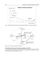
Ultra wideband (UWB) communications is one of the most promising recent developments
in wireless world for high-speed applications as shown in figure 1. In addition, the use of
millimeter-waves has allowed in recent years the development of wireless communications:
unlicensed short-range (57 – 64 GHz), outdoor semi-unlicensed point to point links (71 - 76
GHz, 81 - 86 GHz, and 92 - 95 GHz), automotive radar (76 - 77 GHz), and imaging sensor (84
– 89 GHz and 94 GHz) systems.
Fig. 1. High-speed wireless applications
The use of microwave frequencies (3.1–10.6 GHz) for UWB systems is actually subject of
intensively research. In order to analyze a different very promising approach, this chapter
proposes the use of a millimeter-wave carrier for UWB communication systems. Through
Ultra Wideband Communications: Novel Trends – System, Architecture and Implementation
332
the very recent researches, it is known that millimeter-wave technology enables the design
of compact and low-cost wireless transceivers which can permit convenient terminal
mobility up to Gb/s data-rates.
The chapter is organized as follows:
Section 2 provides an overview of millimeter-wave technology (60 GHz), compared
with other microwave band communications (5 GHz).
Section 3 states the UWB conventional definition, given by Federal Communications
Commission (FCC), and how to use this special technology into millimeter-wave range.
Section 4 analyses a proposed 60 GHz wireless multiport millimeter-wave system
dedicated to high-speed UWB communications.
Conclusions are summarized at the end of the chapter.
2. Millimeter-wave technology for high-speed communications
Due to the recent dramatic growth of high-bandwidth commercial wireless
communications, the microwave communication bands are becoming over crowded.
Moreover, the ever increasing high-speed and large-channel capacity digital data rates used
in multimedia wireless communications are requiring millimeter-wave bandwidths
(frequencies between 30 GHz and 300 GHz). For example, a TV at home will be able to
access all sources in the house: a "box" in the lounge, a PlayStation in the bedroom, or a
DVD reader in another room through a wireless system focusing on the 60 GHz band.
The 60 GHz band is of much interest since a massive amount of unlicensed spectrum (5
GHz) has been allocated worldwide for dense wireless local communications (Cabric et al,
2006; Park & Rappaport, 2007; Engen, 1977; Yacabe et al, 2001). A couple of multimedia
applications calling for wireless transmission over short distances are existing, such as
wireless IEEE 1394 (actually this is an international standard digital interface that can run
up to 400 Mb/s over a thin cable), wireless high-resolution TV and videoconferences,
wireless internet download of lengthy files, wireless direct communication between
notebooks and related devices, patient monitoring in hospitals (patients can freely walk
within the hospital grounds with devices that transmit ECG (Electro-Cardio-Gram), blood
pressure information, etc), remote controls, and wireless embedded systems, etc. This
wide range of applications requires low–cost equipment operating at hundred of megabits
per second.
In the European Advanced Communication Technology and services (ACTS) program, the
40 and 60 GHz have been addressed by various research projects with target radio bit rates
of 150 Mb/s. In Japan, the Multimedia Mobile Access Communication (MMAC) committee
is looking into the possibility of Ultra-high speed wireless indoor LANs supporting 156
Mb/s using 40 and 60 GHz. In the United States, the Federal Communications Commission
(FCC) sets aside the 59-64 GHz frequency band for general unlicensed applications. This is
the largest contiguous block spectrum ever allocated. Thus, a spectral space has been
assigned around 60 GHz having a worldwide overlap, as shown in figure 2.
The 60 GHz band can not only achieve very high data rates several Gbit/s but has many
other characteristics for applications in millimeter wave range:
An atmospheric oxygen absorption of 10-15 dB/Km. Indeed, the oxygen have a
resonant frequency of 60 GHz. So the transmitted energy is absorbed very quickly by
oxygen in the air. (90 % of energy is absorbed by oxygen at 60 GHz).
88 dB/Km due to the free space path loss as demonstrated using Friis transmission
equation:
60 GHz Ultra Wideband Multiport Transceivers
for Next Generation Wireless Personal Area Networks
333
Fig. 2. Unlicensed bandwidth – 60 GHz
2
2
4
rtr
tr fs
t
PGG
GG A
P
R
(1)
P
r
and P
t
= Power of the received and transmitted signals, respectively
G
r
and G
t
=Gain of the antennas of receiver and transmitter, respectively
= free-space wavelength
R= distance between transmitter and receiver
2
2
4
fs
A
R
(2)
8
9
310
5
60 10
c
mm
f
(3)
c = speed of the light
f = frequency
The Friis path loss equation shows that, for equal antenna gains, path loss increases
with the square of the carrier frequency. Therefore 60 GHz communications must
content with an additional 22 dB of path loss when compared to an equivalent 5 GHz
system. Then, the free space path loss will be around 88 dB for 10 m and 68 dB for a
distance of 1 m, at this very high carrier frequency. The space path loss attenuation for a
distance of 10m is calculated for different frequencies, as shown in table 1.
One of the major limitations of the maximum range for a link at 60 GHz is the attenuation
due to rain. In fact, the rainfall of a region is even considered as limiting factor more than
the absorption of oxygen. The 60 GHz links shall be constructed in specific way to be able
to overcome the rain limitations and will therefore vary according to different regions.
The maximum distance increases when the rate of rainfall decreases. In regions with
moderate rainfall, attenuation due to rain can be twice higher than oxygen and can be up
to three times higher in regions with high rainfall.
Ultra Wideband Communications: Novel Trends – System, Architecture and Implementation
334
Frequency Wavelength Free Path Attenuation
2.4 GHz 125 mm 30 dB
5 GHz 60 mm 66 dB
60 GHz 5 mm 88 dB
Table 1. Space attenuation for different frequencies
The very high attenuation suffered by the 60 GHz links permits the frequency reuse
in very close areas. Thus it is possible to deploy multiple devices operating at the
same frequency in a high density pattern and without any risk of interference
between them.
The 60 GHz band advantage is to be in the millimeter wave length range. Thus, it is
very small, allowing high degree integration for all elements: filters, passive
components and antennas. The 60 GHz antennas have a smaller form factor than 5 GHz
antennas, as antenna dimensions are inversely proportional to carrier frequency. For
example, to obtain an antenna with a gain of 40 dBi and beam width of 1°, the size of
the antenna at 60 GHz will be ten times smaller than at 6 GHz. Therefore, at 60 GHz it is
possible to produce very compact low-cost antennas with higher directivity. In fact,
future high data-rate WLAN will be certainly realized using smart antennas to reduce
the power consumption, the link budget and the multipath effects.
This high and severe attenuation makes the 60 GHz band unsuitable for long-range (>2
Km) communications, so it can be entirely dedicated for short-range use (<50 m), where
this supplementary attenuation has no significant impact. This makes the 60 GHz band of
hugely interesting for many types of short-range wireless applications, as WPANs
(Wireless Personal Area Networks) and WLANs (Wireless Local Area Networks). These
products are proprietary systems or based on the IEEE 802.11 standards. These products
operate in the 2.4 and 5.8 GHz bands and provide a user capacity up to 54 Mb/s.
Currently, IEEE 802.15.3c and WirelessHD, the two well-known 60 GHz standards for
WLANs and WPANs, are capable to deliver Gb/s streamed video and audio (Daniels &
Health, 2010).
In the last decade, intensive researches have been done, especially in terms of designing new
millimeter wave components operating over the V-band frequency (50 - 75 GHz). Through
those papers and publications, it has been proved that the millimeter-wave frequencies
enable the design of compact low-cost wireless millimeter-wave communications front-ends
which can permit convenient terminal mobility up to Gb/s data-rates (Smulders et al, 2007;
Smulders, 2002; Collonge et al, 2003; Tatu & Moldovan, 2007).
3. UWB in millimeter-wave communications
Before explaining how the UWB characteristics can be reflected in millimeter-wave
communications, let’s first give a brief description of UWB principles.
The recent development of digital technologies in civil and military fields (radar, instrument
for earth observation and space, etc ) associated with the telecommunications (WiFi /
WiMAX, WLAN, GPS) demonstrates the great possibility to optimize the use of allocated
frequency bands. The FCC defines UWB as "any radio technique that has a bandwidth
exceeding 500 MHz or greater than 25% of its center frequency”. The UWB technology is
60 GHz Ultra Wideband Multiport Transceivers
for Next Generation Wireless Personal Area Networks
335
dedicated for transmitting wireless data with a throughput up to several hundreds of
Mbit/s. UWB presents itself as an evolution of both Bluetooth and USB wireless. It is a radio
technology based on the generation of very short duration pulse over a wide frequency
band, hence its name.
In the United States, the FCC has reserved microwave frequency bands between 3.1 and 10.6
GHz for UWB devices. However, in Europe, the frequencies are reduced to the band
between 6 and 10 GHz (3 GHz less than in the U.S.). UWB technology is used for
radar/sensors, communications, radio astronomy, imaging systems and automotive anti-
collision systems. Currently, UWB is already authorized for licensed use in the United
Kingdom for the defects detection in runways.
UWB is a good alternative for domestic radio networks (WLAN and WPAN) that is found in
the networked home, hotel, conference locations, administrative sites, and all places that do
not want the hassle of wiring. Figure 3 gives an idea about the possible applications of
UWB, regarding the mobility, costs, speed, and cost, etc.
Fig. 3. UWB applications
Although these excellent advantages for microwave UWB, there are some disadvantages at
the same time:
Relatively low frequency carrier
Low data rate compared to huge ones required in the actual market
Frequency distortion over wide bandwidth
Compared to conventional microwave UWB technology, 60 GHz millimeter-wave
communications will operate in currently unlicensed spectrum (57 – 64 GHz) and will
provide high data-rates up to several Gb/s, as detailed in paragraph 2. Hence, the
millimeter-wave communications can be largely considered to be used for UWB purposes
(WLANs and WPANs). This is the main concern of the following paragraph.
Ultra Wideband Communications: Novel Trends – System, Architecture and Implementation
336
4. UWB at 60 GHz: different approaches
There are many different ways to use the UWB at millimeter-wave frequencies. In this
paragraph, two approaches are considered:
Transposition of conventional impulse radio at millimeter-wave
Direct use of inherent wide-band into a multi-port interferometer
4.1 Up-conversion of an UWB impulse radio signal (IR-UWB) in the 60 GHz frequency
range.
(Deparis et al, 2005) have demonstrated that the impulse radio-UWB used in the 60 GHz
band can provide both transceiver simplicity, and high data rate. Their proposed transmitter
contains a voltage controlled oscillator (VCO) working at 30 GHz, a double frequency up-
converter to reach the 60 GHz frequency, and a pulse generator (1
st
pulse generator) to
generate the pulse position modulation (PPM) pulses in order to modulate the transmitted
signal at 60 GHz. This modulation is realized with a switch in ∏-topology, as shown in
figure 4. After amplification, Gaussian pulses are transmitted over several GHz bandwidth
centered into the 60 GHz band (Tatu el al, 2009).
At the meanwhile, the receiver is composed of a low noise amplifier (LNA), a detector at 60
GHz, and a fast sampling and hold - S/H (Win & Scholtz, 2000; El Aabbaoui et al, 2005;
Deparis et al, 2004). A pulse generator (2
nd
pulse generator) is used to control the S/H
circuit. The receiver may contain either a mixer or a detector. If a mixer is implemented, a
millimeter-wave oscillator is needed. However, the oscillator is not needed when a topology
with detector is chosen, as shown in figure 5.
Fig. 4. Transmitter at 60 GHz.
Fig. 5. Receiver at 60 GHz.
X2
Switchin∏
topology
A
1
st
pulse
generator
Detector
60GHZ
ADC
2
nd
pulse
generator
LNA
Correlator
S/H
60 GHz Ultra Wideband Multiport Transceivers
for Next Generation Wireless Personal Area Networks
337
The main advantage of this architecture is that no phase information is needed, and thus, no
sophisticated coherent stable sources or carrier recovery circuits are involved. This impulse
radio-UWB/60 GHz approach can offer transceiver simplicity, high-data rate and is suitable
for future low-cost high speed wireless transceivers.
4.2 Proposed 60 GHz transceiver based on six-port circuits
The main objective of this paragraph is to analyze and discuss a 60 GHz transceiver based
on six-port circuits. Our target is to provide a transmission bandwidth exceeding 500 MHz,
so the proposed architecture can be considered as part of UWB communications systems.
4.2.1 S-parameters and scattering matrix
For high frequencies and since it is very difficult to measure the voltage signal and energy,
the scattering parameters [S] are used instead and considered as a convention for describing
the RF and microwave waves. In microwave circuits, the required parameters are the
amplitude and the phase of the signals. Many electrical properties can be expressed using
the S-parameters such as the transmission coefficients, return loss and SWR (standing wave
ratio) parameters. S-parameters can be calculated using analytical techniques of network
analysis or measured with vector network analyzer equipment. Once identified, these S-
parameters can be set in matrix form, called scattering matrix. For example, a two-port
network microwave system as shown in figure 6 is represented as follows:
Fig. 6. Quadripole microwave system.
The wave’s equations and the S-parameters scattering matrix are:
1111122
bSaSa
(4)
2211222
bSaSa
(5)
111121
221222
bSS a
bSS a
(6)
a
i
: Incident wave
b
i
: Reflected wave
S
11
: Input reflection coefficient
S
12
: transmission coefficient
S
21
: transmission coefficient (gain)
S
22
: Output reflection coefficient
Ultra Wideband Communications: Novel Trends – System, Architecture and Implementation
338
4.2.2 Six-port modeling versus conventional: architecture equivalence
The six-port circuit is a conventional linear passive component, which consists of several
couplers, connected by transmission lines. The idea of using a six-port structure to determine
the phase of a microwave signal was first presented in 1964 (Cohn & Weinhouse, 1964). The
six-port circuit can be considered as a black box with two inputs, one for the reference signal
from local oscillator and one for the RF signal to identify, and four outputs. Using an
appropriate algorithm, the amplitude and phase of the RF signal to identify can be determined
by measuring the four power signals of the diodes at the outputs of the six-port.
The six port model used in this chapter consists of four 90° hybrid couplers interconnected
by transmission lines and four power detectors, as shown in figure 7 (Tatu et al, 2005, 2006).
The signals a
5
and a
6
are two normalized waves’ inputs and related to local oscillator
(LO) and radio-frequency signals, respectively. As known, the hybrid coupler splits
Fig. 7. Six-Port block diagram.
a signal with a 90° phase shift between output ports while maintaining high isolation
between the ports. Based on this definition and using the power equations of hybrid
couplers, the four outputs wave’s equations b
i
can be resolved as shown in the following
equations:
56
1
22
aa
b
jj
(7)
56
2
22
aa
b
j
(8)
56
3
22
aa
b (9)
56
4
22
aa
bj (10)
2
5
a
Z
0
5
6
a
4
2
6
1
3
5
a
2
5
a
2
6
a
2
6
a
j
65
2
1
aja
65
2
1
jaa
65
2
1
aa
65
2
1
aaj
90
Z
0