Wind Farm Impact in Power System and Alternatives to Improve the Integration Part 12 potx
Bạn đang xem bản rút gọn của tài liệu. Xem và tải ngay bản đầy đủ của tài liệu tại đây (1.43 MB, 25 trang )
Wind Farm – Impact in Power System and Alternatives to Improve the Integration
264
10
20
30
40
50
60
20
40
60
0
0.2
0.4
0.6
0.8
1
Original State
Next State
Transition Probability
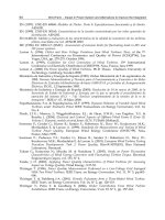
Fig. 15. Gaussian transition probabilities for M = 64 states
10
20
30
40
50
60
20
40
60
0
0.2
0.4
0.6
0.8
1
Original State
Next State
Transition Probability
Fig. 16. Weibull transition probabilities for M = 64 states
Modeling Wind Speed for Power System Applications
265
0 2 4 6 8 10 12 14 16 18
0
0.02
0.04
0.06
0.08
0.1
0.12
0.14
0.16
Wind speed m/s
State Probability
Theoritical
Statistical
Fig. 17. Weibull state probabilities for M = 16 states
-3 -2 -1 0 1 2 3
0
0.02
0.04
0.06
0.08
0.1
0.12
0.14
Normalized wind speed m/s
State probability
Theoritical
Statistical
Fig. 18. Gaussian state probabilities for M = 16 states
Wind Farm – Impact in Power System and Alternatives to Improve the Integration
266
Applying the quantization process and Markov state model to the decomposed wind speed
signals presented in Figure 10 (16-year time series in hourly resolution) results in log normal
distribution of wind speed state probabilities. The final results of the state probabilities are
shown in Figures 19 - 21. Figures 22 – 24 show the transition probabilities for each
decomposed wind speed signal. It is shown that smooth transitions appear in medium and
low frequency component signals (i.e., centered around the diagonals), while high
frequency component transition probabilities exhibit significant non-uniformities and
disruptions due to fast changes and high frequencies variations driving the high frequency
decomposed wind speed signal.
Fig. 19. Lognormal state probabilities (M = 128) for high frequency wind signal.
Modeling Wind Speed for Power System Applications
267
Fig. 20. Lognormal state probabilities (M = 128) for medium frequency wind signal.
Fig. 21. Lognormal state probabilities (M = 128) for low frequency wind signal.
Wind Farm – Impact in Power System and Alternatives to Improve the Integration
268
Fig. 22. Lognormal transition probabilities (M = 128) for high frequency wind signal.
Fig. 23. Lognormal transition probabilities (M = 128) for medium frequency wind signal.
Modeling Wind Speed for Power System Applications
269
Fig. 24. Lognormal transition probabilities (M = 128) for low frequency wind signal.
5. Conclusion
This chapter characterizes wind speed signal using stochastic time series distribution models.
It presents a short term wind speed prediction model using a linear prediction method by
means of FIR and IIR filters. The prediction model was based on statistical signal
representation by a Weibull distribution. Prediction accuracies are presented and they show
independencies on past value expect for the most recent one. These in turn validate a Markov
process presentation for stationary wind speed signals. The chapter also studies the integration
of a complete wind speed pattern from a decomposition model using Fourier Transform for
different wind time series models defined by different frequencies of each wind pattern.
Uniform quantization and discrete Markov process have been applied to the short, medium
and long term wind speed time series signals. The actual state and transition probabilities
have been computed statistically based on the counting method of the quantized time series
signal itself. Theoretical state probabilities have been also computed mathematically using
the fitted PDF model. A comparison of the statistical and theoretical state probabilities
shows a good match. Both low and medium frequency signals exhibit smooth variation in
state transition probabilities, while the high frequency component exhibit irregularity due to
fast, short term variations.
6. References
[1] GE Energy, (March 2005), Report on “The Effects of Integrating Wind Power on Transmission
System Planning, Reliability, and Operations” Prepared for:The New York State
Wind Farm – Impact in Power System and Alternatives to Improve the Integration
270
Energy Research and Development Authority. Available online:
[2]
C. Lindsay Anderson, Judith B. Cardell, (2008), “Reducing the Variability of Wind
Power Generation for Participation in Day Ahead Electricity Markets,” Proceedings
of the 41
st
Hawaii Inter national Conference on System Sciences, IEEE.
[3]
Kittipong M., Shitra Y., Wei Lee, and James R., (Nov. 2007), “An Integration of ANN
Wind Power Estimation Into Unit Commitment Considering the Forecasting
Uncertainty,” IEEE Transactions On Industry Applications, Vol., 43, No. 6,
[4]
Marcos S. Miranda, Rod W. Dunn, (2006), “One-hour-ahead Wind Speed Prediction
Using a Bayesian Methodology,” IEEE.
[5]
D. Hawkins, M. Rothleder, (2006), “Evolving Role of Wind Forecasting in Market
Operation at the CAISO,” IEEE PSCE, pp. 234 -238,
[6]
Alberto F., Tomas G., Juan A., Victor Q., (Aug. 2005), “Assessment of the Cost
Associated With Wind Generation Prediction Errors in a Liberalized Electricity
Market,” IEEE Transactions on Power Systems, Vol. 20, No. 3, pp. 1440-1446,.
[7]
Dale L. Osborn, (2006), “Impact of Wind on LMP Market,” IEEE PSCE, pp. 216-218.
[8]
Cameron W. Potter, Micheal Negnevistsky,(2005) “Very Short-Term Wind Forecasting
for Tasmanian Power Generation”, IEEE, TPWRS Conference.
[9]
National weather station, available online,
[10]
B. A. Shenoi, (2006), “Introduction to Digital Signal Processing and Filter Design” John
Wiley & Sons, Inc.
[11]
F. Castellanos, (Aug. 2008), ” Wind Resource Analysis and Characterization with
Markov’s Transition Maatrices,” IEEE Transmission and Distribution Conf., Latin
America,
[12]
Noha Abdel-Karim, Mitch J. Small, Marija Ilic, (2009), “Short Term Wind Speed
Prediction by Finite and Infinite Impulse
[13]
Response Filters: A State Space Model Representation Using Discrete Markov Process”,
Powertech Conf. Bucharest, 2009.
[14]
P. P. Vaidyanathan, (2008), The Theory of Linear Prediction, California Institute of
Technology, 1
st
ed., Morgan & Claypool, 2008
[15]
Yang HE, (2010), Modeling Electricity Prices for Generation Investment and
Scheduling Analysis., Thesis proposal, University of Hong Kong.
12
Modelling and Simulation of a 12 MW
Active-Stall Constant-Speed Wind Farm
Lucian Mihet-Popa
1
and Voicu Groza
2
1
Politehnica University of Timisoara
2
University of Ottowa
1
Romania
2
Canada
1. Introduction
The conventional energy sources such as oil, natural gas, or nuclear are finite and generate
pollution. Alternatively, the renewable energy sources like wind, solar, tidal, fuel cell, etc
are clean and abundantly available in nature. Among those the wind energy has the huge
potential of becoming a major source of renewable energy for this modern world. In 2008, 27
GW wind power has been installed all over the world, bringing world-wide install capacity
to 120.8 GW (GWEC publication, 2009).
The wind energy industry has developed rapidly through the last 20-30 years. The
development has been concentrated on grid connected wind turbines (wind farms) and their
control strategies. Conventional stall wind turbines are equipped with cage rotor induction
generators, in which the speed is almost constant, while the variable speed and variable
pitch wind turbines use doubly-fed induction generators or synchronous generators in
connection with a power converter (partial rate or full rate). The variable speed wind
turbine has a more complicated electrical system than the fixed-speed wind turbine, but it is
able to achieve maximum power coefficient over a wide range of wind speeds and about (5-
10) % gain in the energy capture can be obtained (Hansen, A.D. et.al, 2001).
In this paper a complete simulation model of a 6 x 2 MW constant-speed wind turbines (wind
farm) using cage-rotor induction generators is presented using data from a wind farm installed
in Denmark. The purpose of the model is to simulate the dynamical behaviour and the
electrical properties of a wind turbine existing in a wind farm. The wind farm model has also
been built to simulate the influence on the transient stability of power systems. The model of
each wind turbine includes the wind fluctuation model, which will make the model useful also
to simulate the power quality and to study control strategies of a wind turbine.
2. Wind turbine modelling
In order to simulate the wind turbine as a part of a distribution system, models have been
developed for each element and implemented in the dedicated power system simulation
tool DIgSILENT Power Factory.
The purpose of the model is to simulate the dynamical behaviour and the electrical
properties of a wind turbine. The modelling of the wind turbine should create a model as
Wind Farm – Impact in Power System and Alternatives to Improve the Integration
272
simple as possible from a mechanical point of view, but capable of providing a good
description of the electrical characteristics of a wind turbine.
The wind turbine model consists of different component models: wind model, aerodynamic
model, transmission model and of the electrical components such as induction generator,
soft-starter, capacitor bank and transformer model (Mihet-Popa, 2004). Aerodynamics is
normally integrated with models for different wind conditions and structural dynamics.
The wind turbine is characterized by the non-dimensional curves of the power coefficient C
p
as a function of both tip speed ratio λ, and the blade pitch angle, θ
pitch
. The tip speed ratio is
the ratio of linear speed at the tip of blades to the speed of the wind.
As shown in Fig. 1, the wind model generates an equivalent wind speed u
eq
, which, together
with the blade pitch angle θ
blade
and rotor speed ω
rot
, are input to the aerodynamic block. The
output of the aerodynamic model is the aerodynamic torque T
rot
, which is the input for the
transmission system together with the generator speed ω
gen
. The transmission system has as
output the mechanical torque T
hss
on the high-speed shaft, which is used as an input to the
generator model. Finally, the blade angle control block models the active control loop, based
on the measured power and the set point.
A simplified block diagram of the wind turbine model is presented in Fig. 1.
2.1 The wind speed model
The wind models describe the fluctuations in the wind speed, which influence the power
quality and control characteristics of the wind farm. Thus, the wind speed model simulates
the wind speed fluctuations that influence the fluctuations in the power of the wind
turbines. The wind acting on the rotor plane of a wind turbine is very complex and includes
both deterministic effects (mean wind, tower shadow) and stochastic variations due to
turbulence (Mihet-Popa, 2003).
Fig. 1. The block diagram of a simplified model for a constant-speed wind turbine using
induction generator.
The simulations shown in Fig. 2 illustrate the effect of the rotational sampling. This hub
wind speed is used as input to the rotor wind model to produce an equivalent wind speed
Modelling and Simulation of a 12 MW Active-Stall Constant-Speed Wind Farm
273
(u
eq
), which accounts for the rotational sampling on each of the blades. The wind speed
(wspoint), which influences the power quality, should be filtered to generate a hub wind
speed (wsfic).
Figure 2 shows a simulation result for one wind turbine, based on a look-up table, at an
average wind speed of 10 m/s.
As expected, both wind speed models fluctuate with three times the rotational frequency
(3p).
2.2 The aerodynamic model
A wind turbine is essentially a machine that converts the kinetic energy of the moving air
(wind) first into mechanical energy at the turbine shaft and then into electrical energy (Heier
S., 1998).
Fig. 3 describes the conversion of wind power (P
WIND
) into mechanical (P
MEC
) and thereafter
into electrical power (P
EL
).
Fig. 2. Rotor wind speed and hub wind speed model.
The interaction of the turbine with the wind is complex but a reasonably simple
representation is possible by modelling the aerodynamic torque or the aerodynamic power
as described below. Aerodynamic modelling also concerns the design of specific parts of
wind turbines, such as rotor-blade geometry and the performance prediction of wind farms.
The force of the wind creates aerodynamic lift and drag forces on the rotor blades, which in
turn produce the torque on the wind turbine rotor (Hansen et. al, 2003).
Wind Farm – Impact in Power System and Alternatives to Improve the Integration
274
PWIND
PMEC
PEL
n 1
n 2
3
IG
Fig. 3. A block diagram of the power conversion in a wind turbine.
The aerodynamic torque is given by:
3
1
(, )
2
aero
rot p pitch
rot
P
TRC
(1)
Where P
aero
is the aerodynamic power developed on the main shaft of a wind turbine with
radius R at a wind speed u
eq
and air density ρ. It is expressed by:
23
1
(, )
2
aero e
qp p
itch
PRuC
(2)
The air density ρ is depending on the temperature and on the pressure of the air.
The dimensionless power coefficient C
p
(λ, θ
pitch
) represents the rotor efficiency of the turbine.
It is taken from a look-up table, which contains the specific aerodynamic characteristics for
the turbine.
This coefficient depends on the tip speed ratio /
rot e
q
Ru
and on the blade angle θ
pitch
,
ω
rot
denotes the rotor speed. For a constant speed turbine, the power coefficient decreases
when the wind speed increases (λ small). This fact is used in the passive stall control wind
turbine.
The efficiency coefficient (C
p
) changes with different negative values of the pitch angle (0
0
, -
1
0
, -2
0
, -3
0
) but the best efficiency is obtained for θ
pitch
=0
0
.
The aerodynamic model is based on C
p
curves for the given rotor blades.
2.3 Transmission system model
To describe the impact of the dynamic behaviour of the wind turbine, a simple model is
considered, where the tower bending mode and the flap-bending mode of the wind turbine
are neglected.
It is assumed that all the torsion movements are concentrated in the low speed shaft, as T
lss
.
Emphasis is placed on the parts of the dynamic structure of the wind turbine, which
contributes to the interaction with the grid, i.e. which influence the power. Therefore only
the drive train is considered in the first place because the other parts of the wind turbine
structure have less influence on power.
The drive train model is illustrated in Fig. 4.
The rotor is modelled by inertia
rot
I , low speed shaft only by a stiffness
s
k (the torsion
damping is neglected), while the high-speed shaft is assumed to be stiff. Thus the
transmission is described by the following equations:
Modelling and Simulation of a 12 MW Active-Stall Constant-Speed Wind Farm
275
rot
rot lss
rot
d
ITT
dt
(3)
gen
lss
srot
gear
dT
k
dt n
(4)
It is also assumed that the losses in the gearbox are zero, thus the gear transmits ideally from
the low speed to high speed. The output of the model is:
lss
hss
g
ear
T
T
n
(5)
where
n
gear
is ratio of the gear box.
Fig. 4. Drive train model of the wind turbine.
2.4 The induction generator model
The induction machine model is a combined mechanical and electro-magnetic model. The
mechanical model includes the inertia of the generator rotor in the generator model.
Induction generators are 4/6 pole single cage machines (2MW/500kW) implemented using
their nominal nameplate parameters.
The torque–slip and short-circuit test curves are used as a definition in the built–in
DigSILENT asynchronous machine model.
Electrical parameter variations and different cage rotors with rotor current displacement can
also be considered (DIgSILENT Power Factory user manual, 2010).
In the simulations presented in the following the induction generator is a single cage
machines implemented using their nominal nameplate parameters, as can be seen in Fig. 5.
To wider the range of the output electrical power the generators are with double stator
windings (2/0.5MW).
The switching between 4/6 pole operation is made as a function of output power.
2.5 The soft-starter model
In order to reduce the transient current during connection of the induction generator to the
grid a soft starter is used. The soft-starter could minimize the impact of machine starting on
the electrical network and also could helps to prolong the life of mechanical components.
Wind Farm – Impact in Power System and Alternatives to Improve the Integration
276
Fig. 5. Induction generator of 2 MW rating power implemented in DIgSILENT simulation
tool based on its torque-slip curve and name plate values.
A soft-starter is an ac voltage controller in which the voltage is adjusted through the setting
of the thyristors firing angle (Deleroi & Woudstra, 1991).
The soft-starter is designed to meet the industrial requirements of wind generator
applications. In DIgSILENT Power Factory the soft starter is a stand-alone element. The
commutation devices are 2 thyristors connected in anti-parallel for each phase.
The soft-starter modelling and its control implementation are described in details and a set
of simulations are performed using DIgSILENT software simulation tool.
When the wind generator is driven to just bellow synchronous speed (approximately 93 %),
under the action of its aerodynamic rotor, the soft starter is connected and using the firing
angle control the machine is connected over the grid.
The connection diagram of soft starter fed a 4/6 poles double stator windings induction
machine is presented in Fig. 6 a). Figure 6 b) shows the fully controlled topology with a
delta-connected load. If thyristors are delta-connected, their control is simplified and their
ratings considerably reduced. The delta arrangements generate, in the load, all the odd
harmonics, but no triple harmonics. Harmonics of order 5, 7, 11, 13 … remain.
Modelling and Simulation of a 12 MW Active-Stall Constant-Speed Wind Farm
277
K_byp
K1
K2
K_G500
Softstarter
G2000 G500
3~ 3~
960V
firing angle
control
open
closed
a)
b)
Fig. 6. a) Connection diagram of the soft-starter with induction generators and schematic
diagram of the soft-starter with delta connected load, b).
To get the controller started, two or three switches must be fired simultaneously to provide
the path for current necessary to maintain the on-state. Switching variables may be
introduced for 2 thyristors connected in anti-parallel for each phase and defined as equal to
1 when a given thyristor is conducting and equal to 0 otherwise. It can easily be
demonstrated that the output voltages of the controller (soft-starter) are given by (6):
AB
ab
bc BC
ca CA
11
ab - a - b
22
V
V
11
V =-c bc -b×V
22
VV
11
-c-a ca
22
(6)
Wind Farm – Impact in Power System and Alternatives to Improve the Integration
278
Depending on the firing angle, three modes of operation of the soft-starter can be
distinguished, with a purely resistive load (Rombaut, et. al, 1987):
1.
060
: 2 or 3 switches conducting (in either direction);
2.
60 90
: 2 switches conducting;
3.
90 150
: none or two switches conducting.
Analysis of operation of the controller with RL load is difficult since the extension angle and
the so-called limit angle must be known. Mode 2, characterized by rapid changes of the
output currents is impossible due to the load inductance. The ranges of the two remaining
operation modes are φ ≤ α < α
lim
for mode 1 and α
lim
≤ α < 150° for mode 3. The limit angle
can be determined numerically from (7):
3()
lim
3()
lim
4
sin( )
21
3
sin( )
2
tg
tg
e
e
(7)
The equations for the RMS output voltage, of the fully controlled soft-starter with purely
resistive and inductive loads are provided bellow:
Resistive load:
133
sin(2 )
24
out in
VV
(8)
for 0 60
133
sin(2 )
24 6
out in
VV
(9)
for 60 90
15 3 3
sin(2 )
42 4 3
out in
VV
(10)
for 90 150
Inductive load
15 3
3sin(2)
22
out in
VV
(11)
for 90° ≤ α < 120°
15 3
3sin(2)
22 3
out in
VV
(12)
for 120° ≤ α < 150°
The envelope of control characteristics given by (8) through (12) is shown in Fig. 7. The
relationship between the firing angle and the resulting amplification of the soft starter is
Modelling and Simulation of a 12 MW Active-Stall Constant-Speed Wind Farm
279
highly non-linear and depends additionally on the power factor of the connected element. In
the case of a resistive load α can vary between 0 (full on) and 90 (full off) degrees. While in
the case of a purely inductive load α varies between 90 (full on) and 180 (full off) degrees.
For any power factor in between, it will be somewhere between these limits, as can also be
seen in Fig. 7.
In DIgSILENT the control parts (electrical controllers) of the wind turbine system, as the
soft-starter control implementation, are written in the dynamic simulation language DSL.
DSL implementation includes a complete mathematical description of (time-) continuous
linear and nonlinear systems. A DSL model can also be converted into a graphical
representation.
Fig. 7. Control characteristic, Vout=f(α), for a fully controlled soft-starter (Rombaut, 1987).
Fig. 8 shows the soft-starter composite model implemented in DIgSILENT, in which
“Control slot” represents the soft-starter controller while “Soft starter slot” is a block for
checking the soft-starter state (working / bypassed).
Fig. 8. Soft-starter composite model implemented in DIgSILENT.
The firing angle (α) is calculated according to the amplification factor (K
in
) so that if Kin
varies from 0 to 1, α will take values starting from a1 down to a2, (Mihet-Popa, L. et.al,
2008).
Wind Farm – Impact in Power System and Alternatives to Improve the Integration
280
221
0
1
180
in
aaaK
(13)
In witch a1, a2-maximum and minimum angles in degrees and a, b, c-switching variables for
thyristors;
3. Control strategies for wind turbines
Wind turbines are designed to produce electrical energy as cheaply as possible. Therefore
there are generally designed so that they yield maximum output power at wind speeds
around (12-15) meters per second (Hansen, 2001).
In case of stronger winds it is necessary to waste a part of the excess energy of the wind in
order to avoid damaging the wind turbine. All wind turbines are therefore designed with
some sort of power control.
There are two different ways of doing this safely on modern wind turbines: pitch control
and active stall control, as will be described as follows.
3.1 Pitch controlled wind turbines
On a pitch controlled wind turbine the electronic controller checks the output power of the
turbine several times per second. When the output power becomes too high, it sends an
order to the blade pitch mechanism which immediately pitches (turns) the rotor blades
slightly out of the wind. Conversely, the blades are turned back into the wind whenever the
wind drops again. The rotor blades thus have to be able to turn around their longitudinal
axis (to pitch). During normal operation the blades will pitch a fraction of a degree at a time
- and the rotor will be turning at the same time. Designing a pitch-controlled wind turbine
requires some clever engineering to make sure that the rotor blades pitch exactly the amount
required. The pitch mechanism is usually operated using hydraulics or electric stepper
motors (Heier, 1998 & Muljadi, 1999).
As with pitch control it is largely an economic question whether it is worthwhile to pay for
the added complexity of the machine, when the blade pitch mechanism is added.
3.2 Stall controlled wind turbines
Stall controlled (passive stall controlled) wind turbines have the rotor blades bolted onto the
hub at a fixed angle. The geometry of the rotor blade profile however has been
aerodynamically designed to ensure that the moment when the wind speed becomes too
high ; it creates turbulence on the side of the rotor blade which is not facing the wind. This
stall prevents the lifting force of the rotor blade from acting on the rotor. As the actual wind
speed in the area increases, the angle of attack of the rotor blade will increase, until at some
point it starts to stall. If you look closely at a rotor blade for a stall controlled wind turbine
you will notice that the blade is twisted slightly as you move along its longitudinal axis. This
is partly done in order to ensure that the rotor blade stalls gradually rather than abruptly
when the wind speed reaches its critical value. The basic advantage of stall control is that
one avoids moving parts in the rotor itself, and a complex control system (Mihet-Popa, L.,
2003).
A normal passive-stall controlled wind turbine will usually have a drop in the electrical
power output for higher wind speeds, as the rotor blades go into deeper stall. On the other
hand, stall control represents a very complex aerodynamic design problem, and related
Modelling and Simulation of a 12 MW Active-Stall Constant-Speed Wind Farm
281
design challenges in the structural dynamics of the whole wind turbine, e.g. to avoid stall-
induced vibrations.
3.3 Active stall controlled wind turbines
An increasing number of larger wind turbines (1 MW and more) are developed with an
active stall power control mechanism. Technically the active stall turbines resemble pitch-
controlled turbines, since they have pitch able blades. In order to get a reasonably large
torque (turning force) at low wind speeds, the wind turbines will usually be programmed to
pitch their blades much like a pitch controlled wind turbine at low wind speeds. Often they
use only a few fixed steps depending upon the wind speed.
When the turbine reaches its rated power, however, it will notice an important difference
from the pitch controlled wind turbines: If the generator is about to be overloaded, the
turbine will pitch its blades in the opposite direction from what a pitch-controlled wind
turbine does. In other words, it will increase the angle of attack of the rotor blades in order
to make the blades go into a deeper stall, thus wasting the excess energy in the wind.
One of the advantages of active stall is that one can control the active power more accurately
than with passive stall, so as to avoid overshooting the rated power of the turbine at the
beginning of a gust of wind. Another advantage is that the wind generator can be run
almost exactly at the rated power of the machine at all high wind speeds.
3.4 Rotor efficiency under stall and pitch controlled wind turbines
The output power of wind turbines varies with wind speed, but is not proportional to it, as
the energy that the wind contains increases with the cube of the wind speed. At low wind
speeds (1-3 m/s), wind turbines are shut down, as they would be able to generate little or no
power (Fig. 9).
Wind turbines only start-up at wind speeds between 2.5 and 5 m/s, known as the “cut-in”
wind speed. “Nominal” or “rated” wind speed, at which nominal output power is reached,
is normally between 12 and 15 m/s. The precise value depends on the ratio of generator
capacity to rotor surface area, and is a design variable. Finally, any wind turbine has a “cut-
out wind speed”: this is the wind speed at which the turbine is shut down to avoid
structural overload. Its value is around 25 m/s for IEC Wind class I and II turbines. For IEC
Wind Class III turbines, which generate maximum output power at lower wind speeds, the
cut-out value is in the range of 17-20 m/s. Wind turbines are shut down if the 10-minute
average of the wind speed is above this design value. Below nominal wind speed, the aim is
to maximize rotor efficiency (Fig. 9).
The rotor efficiency depends on the ratio of the rotor blade tip speed and wind speed,
known as the “tip speed ratio” (λ), described by:
/
rot e
q
Ru
(14)
The tip speed ratio of a fixed speed wind turbine cannot be controlled, as the rotor speed (and
thus the blade tip speed) is fixed. Nevertheless, the tip speed ratio varies with wind speed, and
thus reaches the optimum value at one wind speed only in case of fixed speed designs (or at
two speeds if the wind turbine can operate at two different, but constant, rotor speeds).
With a variable speed wind turbine, the tip speed ratio varies, and depends both on wind
speed and rotor speed. For maximum rotor efficiency, the tip speed ratio must be
Wind Farm – Impact in Power System and Alternatives to Improve the Integration
282
maintained at the value that corresponds to optimum rotor efficiency (usually 6-9) at all
times. This is achieved by controlling the rotor speed accordingly. The higher aerodynamic
efficiency that is thus achieved explains why a variable speed turbine generates more energy
for the same wind speed regime.
At wind speeds below nominal, the aim is to extract energy from the wind as efficiently as
possible; however, this ceases to apply above nominal wind speed, as this would overload
the generator and/or the converter system. Above nominal wind speed, therefore, the
mechanical power extracted from the wind must remain constant. To achieve this, the
aerodynamic rotor efficiency must be reduced when the wind speed increases, as can also be
seen in Fig. 9.
Fig. 9. Typical power curves and operation areas of a stall (dashed line) and pitch controlled
(solid line) wind turbines.
In a stall controlled wind turbine, the blades are designed such that the rotor efficiency
“collapses” at high wind speeds. Due to the blade design, this behaviour is intrinsic, and no
active control systems are required to achieve the aerodynamic efficiency reduction. In a
pitch controlled wind turbine, the blades are gradually turned out of the wind, so the wind
impact angle changes and the aerodynamic efficiency is reduced. In this case active stall
control is applied, by means of hydraulics or an electric drive system. The input variable for
the pitch controller is the rotor speed, as it is depicted in Fig. 10.
Modelling and Simulation of a 12 MW Active-Stall Constant-Speed Wind Farm
283
The higher the rotor speed, the more the blades are turned out of the wind. The blades are
turned back into the wind when the rotor speed falls. In general, fixed speed turbines use
stall control for technical reasons, while variable speed turbines are usually equipped with
pitch control.
Fig. 10. Rotor speed control principle for wind speeds above nominal.
The active-stall concept is similar to normal stall power limitation, except that the whole
blade can be rotated backwards (in the opposite direction as is the case with pitch control)
by a few (3-5) degrees at the nominal speed range in order to give better rotor control. The
application of this concept is more or less restricted to fixed speed turbines.
Typical active-stall representatives are the Danish manufacturers Bonus (1 MW and over)
and NEG Micon (now Vestas) (1.5, 2 MW and over).
The difference from active pitch control is not only that the range of blade angle variation is
less, but also that the direction of the variation is opposite.
3.5 Control design for an active-stall constant speed wind turbine
A common control concept for megawatt-size wind turbines/wind farms without power
electronic converters is the active stall regulation. An active stall wind turbine is a stall
controlled turbine with variable pitch angle. At high wind speeds, the pitch angle is
adjusted to obtain the desired rated power level. When connecting the wind generator to the
grid, the pitch angle is also adjusted in order to obtain a smooth connection. The use of
active stall control also facilitates the emergency stopping of the turbine.
The control strategy called active-stall constant-speed involves the combined interaction
between wind model, pitch control and the aerodynamics of the wind turbine, as can be
seen in Fig. 11.
The blade angle control block models the active-stall control of the wind turbine based on
the measured power and the reference one (Sorensen, P. et.al, 2001).
The most used electrical generator of an active-stall constant-speed turbine is a cage rotor
induction generator connected to the grid through a soft-starter, as it is shown in Fig. 11.
A clear difference between stall and active stall controlled wind turbines is a pitch actuator
system for variable pitch angles, as can be seen in Fig. 12, which allows the stall effect to be
controlled.
The model of the pitch control system is based on the measured generator power (P
m
) and
the aerodynamic power (P
aero
) of wind turbine as a function of measured wind speed (v
wind
)
at different pitch angles (θ).
Wind Farm – Impact in Power System and Alternatives to Improve the Integration
284
Fig. 11. Block diagram of an active-stall controlled wind turbine with constant speed using a
cage-rotor induction generator
Fig. 12. The block diagram of blade pitch angle control system.
The measured power is compared with its reference (P
ref
) and the error signal (P
err
)
multiplied by pitch angle of power control (f
1
(v
av
)) is sent to the PI-controller producing the
pitch angle demand (θ
dp
), which together with maximum pitch angle-upper limit (θ
max
) are
sent to the pitch limitation non-linear block producing the reference value of the pitch angle
(θ
ref
). The reference value is in the range between the optimised pitch (θ
dp
) and the maximal
pitch angle (θ
max
=90
0
). The maximum value is defined as a function of average wind speed
Modelling and Simulation of a 12 MW Active-Stall Constant-Speed Wind Farm
285
(f
2
(v
av
)). The reference value is, further, compared to the actual pitch angle (θ
pitch
) and the
error signal (θ
e2
) is corrected by the pitch hydraulics.
This control strategy takes its origin in the power coefficient curves C
p
(θ, u), typical for a 2
MW constant speed wind turbine, as it is depicted in Fig. 13.
C
p
represents the rotor (aerodynamic) efficiency of the wind turbine and depends on the
pitch angle θ and on the tip speed ratio λ. In order to achieve maximum power yield for
each wind speed the maximal C
p
and the corresponding θ has to be found.
a)
b)
Fig. 13. Power coefficient (Cp) of a 2MW wind turbine versus wind speed (a), and the tip
speed ration (λ), (b) at different pitch angles.
0 2 4 6 8 10 12 14
0
0.05
0.1
0.15
0.2
0.25
0.3
0.35
0.4
0.45
0.5
lambda
Cp
Pitch 0
Pitch -1
Pitch -2
Pitch -3
Wind Farm – Impact in Power System and Alternatives to Improve the Integration
286
In order to achieve maximum power yield for each wind speed the maximal C
p
and the
corresponding θ has to be found. In fact, the control strategy is characterised by two terms:
the optimal region and the power limiting region. In the optimal region (between start-up
wind speed and nominal wind speed), the output power is designed to fulfil the criterion of
maximal C
p
, which corresponds to the optimal energy capture, by keeping the tip speed
ration (λ) constant. In the power limiting region (between nominal wind speed and cut-out
wind speed), the output power is kept constant, while the wind turbine will pitch the blades
a few degrees every time when the wind changes in order to keep the rotor blades at the
optimum angle. When the wind turbine reaches its rated power, and the generator is about
to be overloaded, the turbine will pitch its blades in the opposite direction. In this way, it
will increase the angle of attack of the rotor blades in order to make the blades go into a
deeper stall, thus wasting the excess energy in the wind.
4. Wind farm modelling
The wind farm contains 6 wind turbines of 2 MW each of them. The model of wind turbine,
presented before, was implemented for each wind turbine.
The layout of the active-stall wind farm is shown in Fig. 14 and a load flow simulation for
one wind turbine in Fig. 15. Each wind turbine is connected to a 10 kV bus bar. The
induction generators, soft-starters, capacitor banks for reactive power compensation and the
step-up transformers are all palaces in nacelle and thus the transformer is considered part of
the wind turbine.
The control of active and reactive power is based on measured reactive power at the point of
common coupling. The wind turbine controller must be able to adjust the wind turbine
production to the power reference computed in the wind farm control system, according to
the demands imposed by the system operator. In case of normal operation conditions the
wind turbine has to produce maximum power. In power limitation operation mode the
wind turbine has to limit its production to the power reference received from the wind farm
controller.
4.1 Electrical diagram
The Fig. 14 contains the grid representation from 50 kV double bus-bar systems down to the
wind turbines. Two 16 MVA 50/10kV transformers are included, one is connected to the
wind farm and one supplies some custom loads.
10 kV cables make the connection between the 10 kV substation and the wind turbines.
As the turbines are placed in groups of 3, a backup cable is also represented on the scheme.
The wind turbine contains also the tower cable making the connection between the 0.96
kV/10 kV transformer and the 10 kV cable at the bottom of the tower. The 10 kV cables are
modelled using the existing DIgSILENT model toolbox.
The power factor compensation units are represented by a capacitor bank on this scheme
and a Static VAR System (SVS) unit. The switching of capacitors is done as a function of
average value of measured reactive power. In order to limit the starting current transients
during the 2 MW generator connections to the grid, a soft starter start-up is used. The
generators are connected when the generator speed is higher than the synchronous speed.
The generators are full load compensated.
Modelling and Simulation of a 12 MW Active-Stall Constant-Speed Wind Farm
287
Fig. 14. 12 MW wind farm diagram implemented in Digsilent.
4.2 Load flow simulation
In Fig. 15 is depicted a case of load flow simulation when the wind turbines are work at
nominal conditions (2MW) and full power factor compensation is used.
5. Simulation results
To evaluate the performance of wind turbine control system a set of simulations are
performed using a power system analysis software-DIgSILENT Power Factory, which
provides the ability to simulate load flow, RMS fluctuations and transient events in the
same software environment. This makes the developed models useful for the power
quality studies as well as for the grid fault studies. The RMS simulations are based on
Wind Farm – Impact in Power System and Alternatives to Improve the Integration
288
Fig. 15. Power-flow simulation for a wind turbine working at nominal conditions.
electro-mechanical transient models, which are simplified models than those used in EMT
simulations. They are more appropriate for the most studies of power quality and control
issues. They are much faster than the instantaneous value simulation compared to the period,
which is simulated. The EMT simulations, as they are based on detailed electromagnetic
transient models, are appropriate for studies of the behaviour during grid faults.
5.1 DIgSILENT power factory software tool
To simulate the wind turbines, models have been developed for each element and
implemented in the dedicated power system simulation tool DIgSILENT (DIgSILENT
Power Factory user manual, 2010). The DIgSILENT simulation tool has a dedicated model
for many components, such as induction generators, which take into account the current
displacements in the rotor, the torque–slip and short circuit test curves. Also models of
synchronous machines, transformers, bus bars, grid models, static converters etc are
provided.