Advances in Spacecraft Technologies Part 1 pot
Bạn đang xem bản rút gọn của tài liệu. Xem và tải ngay bản đầy đủ của tài liệu tại đây (4.02 MB, 40 trang )
ADVANCES IN
SPACECRAFT
TECHNOLOGIES
Edited by Jason Hall
Advances in Spacecraft Technologies
Edited by Jason Hall
Published by InTech
Janeza Trdine 9, 51000 Rijeka, Croatia
Copyright © 2011 InTech
All chapters are Open Access articles distributed under the Creative Commons
Non Commercial Share Alike Attribution 3.0 license, which permits to copy,
distribute, transmit, and adapt the work in any medium, so long as the original
work is properly cited. After this work has been published by InTech, authors
have the right to republish it, in whole or part, in any publication of which they
are the author, and to make other personal use of the work. Any republication,
referencing or personal use of the work must explicitly identify the original source.
Statements and opinions expressed in the chapters are these of the individual contributors
and not necessarily those of the editors or publisher. No responsibility is accepted
for the accuracy of information contained in the published articles. The publisher
assumes no responsibility for any damage or injury to persons or property arising out
of the use of any materials, instructions, methods or ideas contained in the book.
Publishing Process Manager Jelena Marusic
Technical Editor Teodora Smiljanic
Cover Designer Martina Sirotic
Image Copyright Fernando Rodrigues, 2010. Used under license from Shutterstock.com
First published February, 2011
Printed in India
A free online edition of this book is available at www.intechopen.com
Additional hard copies can be obtained from
Advances in Spacecraft Technologies, Edited by Jason Hall
p. cm.
ISBN 978-953-307-551-8
free online editions of InTech
Books and Journals can be found at
www.intechopen.com
Part 1
Chapter 1
Chapter 2
Chapter 3
Chapter 4
Chapter 5
Chapter 6
Chapter 7
Preface IX
Innovative Hardware Technologies 1
Hardware-In-the Loop Simulation System
Construction for Spacecraft On-orbit Docking
Dynamics, Ideas, Procedural and Validation 3
Tongli Chang
Solar Sailing: Applications
and Technology Advancement 35
Malcolm Macdonald
Measurements and Characterization of Ultra Wideband
Propagation within Spacecrafts- Proposal of Wireless
Transmission for Replacing Wired Interface Buses 61
Akihisa Matsubara, Atsushi Tomiki,
Tomoaki Toda and Takehiko Kobayashi
Lubrication of Attitude Control Systems 75
Sathyan Krishnan, Sang-Heon Lee
Hung-Yao Hsu and Gopinath Konchady
Development of Optoelectronic Sensors
and Transceivers for Spacecraft Applications 99
José M. Sánchez-Pena, Carlos Marcos, Alberto Carrasco,
Ricardo Vergaz and Ramón Zaera
Solar Electric Propulsion Subsystem Architecture
for an All Electric Spacecraft 123
Michele Coletti, Angelo Grubisic,
Cheryl Collingwood and Stephen Gabriel
Green Propellants Based on
Ammonium Dinitramide (ADN) 139
Anders Larsson and Niklas Wingborg
Contents
Contents
VI
Use of Space Thermal Factors by Spacecraft 157
N. Semena
The Mechanics Analysis of Desquamation for Thermal
Protection System (TPS) Tiles of Spacecraft 175
Zhang Taihua, Meng Xianhong and Zhang Xing
Cutting Edge State Estimation Techniques 195
Unscented Kalman Filtering for Hybrid
Estimation of Spacecraft Attitude Dynamics
and Rate Sensor Alignment 197
Hyun-Sam Myung, Ki-Kyuk Yong and Hyochoong Bang
Fault-Tolerant Attitude Estimation for Satellite
using Federated Unscented Kalman Filter 213
Jonghee Bae, Seungho Yoon, and Youdan Kim
Nonlinear Electrodynamics: Alternative Field
Theory for Featuring Photon Propagation Over
Weak Background Electromagnetic Fields and
what Earth Receivers Read off Radio Signals from
Interplanetary Spacecraft Transponders 233
Herman J. Mosquera Cuesta
Detection and Estimation of Satellite
Attitude Jitter Using Remote Sensing Imagery 257
Akira Iwasaki
Gas-Kinetic Unified Algorithm for Re-Entering
Complex Flows Covering Various Flow Regimes
by Solving Boltzmann Model Equation 273
Zhi-Hui Li
Aerodynamic Disturbance Force and Torque Estimation
For Spacecraft and Simple Shapes Using Finite Plate
Elements – Part I: Drag Coefficient 333
Charles Reynerson
State Feature Extraction
and Relative Navigation Algorithms for Spacecraft 353
Kezhao Li, Qin Zhang and Jianping Yuan
Novel Control Methods 383
Inertia-Independent Generalized Dynamic
Inversion Control of Spacecraft Attitude Maneuvers 385
Abdulrahman Bajodah
Chapter 8
Chapter 9
Part 2
Chapter 10
Chapter 11
Chapter 12
Chapter 13
Chapter 14
Chapter 15
Chapter 16
Part 3
Chapter 17
Contents
VII
Tracking Control of Spacecraft by Dynamic
Output Feedback - Passivity- Based Approach - 405
Yuichi Ikeda, Takashi Kida and Tomoyuki Nagashio
Linear Differential Games
and High Precision Attitude Stabilization
of Spacecrafts With Large Flexible Elements 423
Georgi V. Smirnov, Anna D. Guerman and Susana Dias
Advanced Attitude and Position MIMO Robust
Control Strategies for Telescope-Type Spacecraft
with Large Flexible Appendages 443
Mario Garcia-Sanz, Irene Eguinoa and Marta Barreras
Fuzzy Attitude Control
of Flexible Multi-Body Spacecraft 471
Siliang Yang and Jianli Qin
Applications of Optimal Trajectory Planning
and Invariant Manifold Based Control
for Robotic Systems in Space 497
Ka Wai Lee, Hirohisa Kojima and Pavel M. Trivailo
Optimal Control Techniques
for Spacecraft Attitude Maneuvers 523
Shifeng Zhang, Shan Qian and Lijun Zhang
Modeling and Control of Space Vehicles
with Fuel Slosh Dynamics 549
Mahmut Reyhanoglu
Synchronization of Target Tracking Cascaded
Leader-Follower Spacecraft Formation 563
Rune Schlanbusch and Per Johan Nicklasson
Rendezvous Between Two Active Spacecraft
with Continuous Low Thrust 585
Yechiel Crispin and Dongeun Seo
Chapter 18
Chapter 19
Chapter 20
Chapter 21
Chapter 22
Chapter 23
Chapter 24
Chapter 25
Chapter 26
Pref ac e
The development and launch of the fi rst artifi cial satellite Sputnik more than fi ve de-
cades ago, propelled both the scientifi c and engineering communities to new heights
as they worked together to develop novel solutions to the challenges of spacecra sys-
tem design. This symbiotic relationship has brought signifi cant technological advances
that have enabled the design of systems that can withstand the rigors of space without
signifi cant maintenance while continuing to provide valuable space-based services
such as telecommunication, television and radio broadcasting, weather forecasting,
navigation assistance and natural disaster assistance. Most recently, these advances
have led to the design and launch of spacecra systems that are autonomous in nature,
such as the Progress and the Automated Transfer Vehicle, which rely on precise sen-
sors and actuators as well as accurate and timely state estimation and control to eff ect
safe proximity navigation and docking operations with li le or no human interaction.
With its 26 chapters divided into three sections, this book brings together critical con-
tributions from renowned international researchers to provide an outstanding survey
of recent advances in spacecra technologies that can be used to design the next gen-
eration of spacecra .
The book is divided into three sections that are focused on the key aspects of space-
cra design. The fi rst section is composed of nine chapters that focus on innovative
hardware technologies. Chapter 1 presents a Hardware-In-the-Loop system design for
development and validation of on-orbit docking requirements. This unique simula-
tor provides realistic on-orbit working conditions for a proposed docking mechanism.
Chapter 2 surveys the state of solar sail technologies. Through an excellent review of
past and current solar sail programs, the missions where solar sail structures may
prove most useful are succinctly analyzed. Chapter 3 deals with the measurement and
characterization of radio propagation with a goal of replacing certain portions of the
wired onboard bus with wireless technology. By substituting a wireless bus for the
traditional wired, several advantages have the potential to be realized to include re-
duction in overall spacecra weight, more fl exibility in spacecra design and more
reliable connections. In Chapter 4, the key fundamentals regarding the lubrication re-
quirements of today’s a itude control systems are studied. Chapter 5 presents several
optoelectrical sensor and transceiver applications to enable more precise measurement
of projectile velocities and optimize free space optical communications systems. A so-
lar electric propulsion subsystem is analyzed in Chapter 6 with the goal of designing
an all electric spacecra . All electric designs have the unique benefi ts of eliminating
the requirements for working with the traditional highly caustic propellants used in
main and a itude control propulsion systems while additionally reducing the control
X
Preface
complexities levied by propellant slosh. Chapter 7 presents a green propellant solution
for traditional propulsion systems that is based on Ammonium Dinitramide (ADN).
Current propellants, such as Ammonium Perclorate and Hydrazine, have excellent
performance qualities but are both highly toxic and thus require special handling
while ADN has the ability to provide nearly the same performance without the in-
herent operational limitations. In Chapter 8, a thermal control subsystem is presented
that is both capable of being used to determine the orientation of the spacecra but is
also independent of the other subsystems and variation of thermal factors due to the
space environment. Chapter 9 closes out this fi rst section by considering the problem of
Thermal Protection System (TPS) tiles becoming debonded from spacecra , potentially
causing catastrophic failure as in the case of the Space Shu le Columbia in 2003.
The second section of the book is composed of seven chapters that center on cu ing-
edge state estimation techniques. Chapter 10 begins the section by defi ning an Un-
scented Kalman Filter (UKF) methodology to estimate the a itude dynamics and align
rate sensors. In framing the benefi ts of the UKF based fi ltering algorithm, which is
designed to approximate the nonlinear dynamics to the second order, a simulation
based comparison is made to a typical fi rst-order approximating Extended Kalman
Filter. Chapter 11 presents a fault-tolerant state estimation technique by using a feder-
ated UKF. By employing a federated UKF, which is based on a decentralized KF, several
advantages that include consideration of increased data and simpler fault detection
and isolation can be gained. In Chapter 12, an analysis of the nonlinear electrody-
namic eff ects on interplanetary spacecra is presented. In this analysis, an alternative
fi eld theory is formulated to help explain anomalous measurements on interplanetary
spacecra . Chapter 13 studies the use of satellite imagery to provide feedback based
detection and estimation for an imaging spacecra ’s a itude ji er. By adding an ad-
ditional image sensor on the focal plane, the anomalous disturbances caused by vibra-
tion originating from such mechanical devices as tracking solar arrays, reaction wheels
and high gain antennas can be more accurately measured and subsequently, a more
precise state can be determined. In Chapter 14, the complex gas dynamic fl ow issues
surrounding atmospheric re-entry and its subsequent eff ect on proper state estima-
tion are addressed and a solution is presented by means of the Bolzman equation. In
Chapter 15, a unique method of estimating the aerodynamic force and torque on low
earth orbiting spacecra by means of fi nite plate elements is presented. Through this
method, a more accurate prediction of the drag coeffi cient for an orbiting spacecra
can be gained with the goal of producing a higher fi delity state estimation. Chapter 16
closes out the second section by presenting a shape and state feature based algorithm
that is based on Mathematical Morphology (MM) to more accurately estimate the state
of an orbiting spacecra . MM, which is an emerging discipline focused on imaging
analysis and processing, possesses several inherent advantages such as its ability to
conduct fast and parallel processing while being simple and easy to operate and thus
makes it desirable for automation and intelligence object detection.
The fi nal section contains ten chapters that present a series of novel control methods
for spacecra orbit and a itude control. Chapter 17 begins this section by presenting
a unique and highly promising methodology to provide three-axis stabilization using
dynamic inversion. By inverting the desired a itude error dynamics for the control
variables that realize the a itude dynamics instead of the inverting the mathemati-
cal model, a global transformation is directly gained without the issues arriving from
XI
Preface
deriving the inverse equations of motions. In Chapter 18, a feedback controller similar
to a Proportional-Derivative (PD) based controller is demonstrated for a potential on-
orbit servicing mission. This PD-like feedback controller is based on the passive system
derived by transforming the full six-Degrees Of Freedom (DOF) relative equations of
motion through coordinate and feedback transformation and proper parameter selec-
tion. Chapter 19 investigates using linear diff erential games and high precision a itude
stabilization schemes to control spacecra with large fl exible appendages. Chapter 20
presents a multi-input multi-output control methodology to simultaneously regulate
the six-DOF spacecra state for a potential imagining spacecra with fl exible append-
ages. Fuzzy control logic is applied to the control problem of a spacecra with fl exible
structures in Chapter 21. By treating the inherently nonlinear and not precisely math-
ematically defi ned spacecra model as a “black box”, the relationship between the in-
puts and the outputs and the behavior represented from this process, called fuzzy con-
trol, is investigated. Chapter 22 studies the application of optimal trajectory planning
and invariant manifold control for on-orbit robotic systems. Given the inherent nature
of these systems with their power and space limitations, coupled with the requirement
for real-time trajectory deconfl iction of any manipulator movement, optimal trajectory
planning has the potential to provide a proper solution. In Chapter 23, an excellent
survey of recent advances in optimal control methods for a itude control is presented.
This survey shines light specifi cally on three specifi c aspects: the minimal energy
maneuvering control problem for rigid spacecra , an a itude determination algorithm
based on the improved gyro-dri model, and the three-axis stabilized control problem
given a momentum wheel control actuator based system. In Chapter 24, a novel set
of control laws are presented to stabilize the vehicle dynamics in the presence of fuel
slosh. These control laws are specifi cally unique due to their modeling of the complete
nonlinear translational and rotational vehicle dynamics. Chapter 25 presents a real-
time control solution to eff ect leader-follower synchronization for the formation fl ying
control problem. Chapter 26 closes out this section and the book by proposing a novel
genetic algorithm based optimal control solution for a given cooperative rendezvous
problem. The results of this control algorithm are further compared to an optimal con-
trol solution based on simulated annealing.
Jason Hall
Naval Postgraduate School
Spacecra Robotics Laboratory
Monterey,
USA
Part 1
Innovative Hardware Technologies
1
Hardware-In-the Loop Simulation System
Construction for Spacecraft On-orbit Docking
Dynamics, Ideas, Procedural and Validation
Tongli Chang
School of Electrical and Mechanical Engineering, Northeast Forestry University,
School of Electrical and Mechanical Engineering, Harbin Institute of Technology,
P. R. China
1. Introduction
The Hardware-In-the-Loop (HIL) simulation system for on-orbit docking dynamics is a
large-scale complex test equipment. It establishes working conditions for the docking
mechanism similar with those on orbit. The kernel of above dynamics HIL simulation
system is a mechanical force and movement actions simulator. Besides the mechanical force
and movement actions simulator, it also includes an environmental simulator, a micro-
gravity simulator and so on.
In a narrow mind, the HIL simulation system for on-orbit docking dynamics refers to the
mechanical force and movement action simulator. It is a feedback system which consists of
the dynamics simulation model and real-time simulaton computer, the hardwares under
test, the force and torque sensor, the motion simulator. The research topic of this paper is
limited in above narrow mind.
The HIL simulation system for on-orbit docking dynamics is a key technology that played
important roles in the lunar excursion of America and in the assembling and re-supplying of
Russian MIR space station. Morden space programme enhance the requirements to the HIL
simulation for spacecraft docking dynamics. International Space Station (ISS) program also
required that the ISS Common Berthing Mechanism (CBM) testing on ground simulator
should be performed under operational vacuum and thermal conditions (Office of NRBMP,
1999).
In the early days, the physical simulators played main roles in docking dyniamics tests.
Because of the development of computor and the complexity of modern docking
mechanism, the HIL simulation technology is applied in the docking dynamics simulation.
The dynamic docking test system (DDTS) is setup in US (Gates & Graves, 1974), and the
integated testing system for docking mechanism was built in former Soviet (Peng et al.,
1992). In1980s, docking dynamic test facility (DDTF) was created for testing the handles-
latch docking mechanism (Crimbert & Marchal, 1987). National space development agency
of Japan built the rendezvous and docking operation test system (RDOTS) testing three-
points handles-latch docking mechanism (Lange & Martin, 2002).
The HIL simulation for spacecraft on-orbit docking is a attractive and promising research
field. Lim et al. (1989) modeled and simulated the Stewart platform of DDTS. They pointed
Advances in Spacecraft Technologies
4
out the inertia matrix has tendency to decouple when the mass of the legs increasing, for
purpose of increasing the rigidity, and relative to the platform. But the inertia power matrix
does not show any noticeable general tendency. Ananthakrishnan et al. (1996) developed a
prediction based feed forward filter to enhance the simulation of contact forces and rebound
velocities during the space docking. They used the off-line acquisition and least-squares
procedure to define the pre-filter. But the characteristic of the simulation/hardware
interface with the pre-filter is not clearly discussed. Zhang (1999) presented the scheme of 6-
DOF HIL simulation system for docking. Guan (2001) simulated the spacecraft docking
dynamics with mathematic simulation and pointed out that rigid-body model of spacecraft
could meet the demand of the research on docking dynamics. Kawabe et al. (2001) adopted
a high speed zero gravity motion simulator, whose frequency response is higher than 40Hz,
to setup a HIL simulation system to research the collision and impact dynamics under zero
gravity. They also validated the HIL simulation system with a drop shaft test. Huang et al.
(2005) presented the spacecraft docking simulation using HIL simulator with Stewart
platform and spring-mass payload. Yan et al. (2007) established a Space docking hybrid
simulation prototype experiment system and stabilized it through adding superfluity digital
damp. The docking dynamics calculation method was setup with spacecrafts docking in
space. Tian et al. (2007) simulated the movement simulator in integrate test platform for
docking mechanism. Zhao et al. (2007) analyzed the dynamometry scheme for semi-physical
simulation platform of space docking mechanism and simulated with single-sensor and
double-sensor schemes separately. The mathematic motion model of two spacecrafts was set
up with two-spacecraft docking model. Zhao & Zhang (2008) analyzed the stability of the
whole system of space docking dynamics simulation with simplified HIL simulation system
based on mass-spring-damp simulated object. Under the proportion controller condition,
the stability of the HIL simulation is analyzed. Wu et al. (2008) took the electro-hydraulic
Stewart of the HIL simulation for on-orbit docking dynamics as a research object, designed a
fuzzy-immune PID control of a 6-DOF parallel platform for docking simulation.
This paper will summarize the research results of author in the HIL simulation for on-orbit
docking dynamics, and present a novel HIL simulation system construction idea based on
simulation/hardware interface. Then, the HIL simulation system building procedurals
based on it are developed. At last, validations of them are done with experimental test.
Even though the HIL simulation system design procedural discussed in this paper is based
on the spacecraft on-orbit docking dynamics, it can meet the demands of other applications.
2. Aim and task of HIL simulation for spacecraft on-orbit docking dynamics
The aim of the HIL simulation for spacecraft on-orbit docking dynamics is to re-emerge the
dynamic process of two spacecrafts on-orbit docking on the earth surface.
The tasks of the HIL simulation for spacecraft on-orbit docking dynamics include testing
docking mechanism, checking buffer characteristics, simulating the dynamic process of two
spacecrafts docking on orbit, defining parameters of docking mechanism, re-emerging
troubles of actual spacecraft docking to help finding solution, checking the initial docking
conditions of spacecraft docking process, testing the action and counteraction of spacecraft
docking process, and so on.
As a large-scale experimental equipment, the HIL simulation system for spacecraft on-orbit
docking dynamics should meet the following requirements to complete its simulation task:
1. Ability to simulate the docking process of various spacecrafts.
Hardware-In-the Loop Simulation System Construction for Spacecraft
On-orbit Docking Dynamics, Ideas, Procedural and Validation
5
2. Ability to check or test various docking mechanisms.
3. Ability to test the actual physical docking mechanism and evaluate its performance.
4. Possibility to output and record necessary process parameters of the experimental test.
5. Feasibility to permit human being participates in the simulation.
Then, four attributes of system design of HIL simulation for spacecraft on-orbit docking
dynamics are brought forward, they are the stability of the dynamics feedback system, the
accuracy of re-emerging the dynamic process, the robust ability of the delay compensator
and the adaptability to the docking mechanism and to the spacecraft. In another words, they
are four fundamental problems of system design of HIL simulation for spacecraft on-orbit
docking dynamics (Chang et al., 2008).
3. Analysis on spacecraft on-orbit docking dynamics
3.1 Initial conditions of on-orbit docking
The initial capturing conditions of two on-orbit docking spacecrafts are shown below
Axial approaching velocity +0.35 m/sec ;
Radial approaching velocity -0.10 ~ +0.10 m/sec ;
Radial deflection -0.30 ~ +0.30 m ;
Pitch and yaw deflection -7.0 ~ +7.0º ;
Roll deflection -15.0 ~ +15.0 º ;
Pose angle velocity -1.0 ~ +1.0 º/sec .
Since the dynamic process of the spacecraft on-orbit docking does always converge, the
initial conditions of on-orbit docking are often the utmost working conditions of the HIL
simulation system for spacecraft on-orbit docking dynamics. Usually, 6DOF’s operational
capabilities of the HIL simulation system (Office of NRBMP, 1999):
• Positional tolerance of ±1.27mm and ±0.10degrees.
• Motion range of ±5 degrees for roll, pitch, and yaw; ±0.15m for translation in the
horizontal plane; and 0.61m for vertical travel.
• Payload weight of 1135kg.
3.2 Segmentation of simulated system
Since the hard wares under test in the HIL simulation system are docking mechanisms, then
the spacecraft on-orbit docking system can be segmented into two parts, shown in Figure 1.
The active docking mechanism on chaser vehicle and the passive docking mechanism on
target vehicle is classified as the hardwares under test, which is simulated with physical
model. And the rest of the simulated system which consists of two spacecraft bodies are
described with the mathematical model, which is translated into a programme which runs
on a real-time simulation computer.
3.3 Dynamics model of on-orbit docking spacecraft bodis
The reference frame
)OXYZ(e
is set on the ground, it is inertia reference frame. Chaser vehicle
body frame
)ZYXO(
11111
e
is set at the mass centre of the chaser vehicle, and target vehicle body
frame
)ZYXO(
22222
e
is set at the mass centre of the target vehicle.
)ZYXO(
33333
e
and
)ZYXO(
44444
e
are at the geometry centre of the assembling surface between docking mechanism
and spacecraft body. The directions of the reference frames are shown in Figure 2. The position
and pose of spacecraft is defined in Figure 3. Euler angles are defined in Figure 4.
Advances in Spacecraft Technologies
6
Docking
mechnism
Spacecraft bodies
Fig. 1. Segmentation of simulated system
Fig. 2. On-orbit docking spacecraft bodies
ψ
ϕ
θ
X
Z
Y
Fig. 3. Definition of position and pose
θ
θ
Z
′
X
′
Y
′
′
O
X
′
′
Z
Z
′
′
′
Y
′
′
′
ψ
ϕ
ϕ
ψ
X
Y
Fig. 4. Definition of Euler angle
Hardware-In-the Loop Simulation System Construction for Spacecraft
On-orbit Docking Dynamics, Ideas, Procedural and Validation
7
When
A stands for the transferring matrix from reference frame
)OXYZ(
to
frame
)ZYXO(
′′′′′′′′
, then
cc ss ccs cs scs
scc -sc
sc sc css cc sss
θψ φθ φθψ φθ φθψ
ψφψ φψ
θψ φθ φθψ φθ φθψ
⋅⋅−⋅⋅⋅+⋅⋅
⎡
⎤
⎢
⎥
=⋅⋅
⎢
⎥
⎢
⎥
−⋅ ⋅+ ⋅⋅ ⋅− ⋅⋅
⎣
⎦
A . (1)
Where s( ) sin( )
Δ
⋅= ⋅; c( ) cos( )
Δ
⋅
=⋅.
The roll, yaw and pitch angles of vehicle
i can be work out with angle velocities of its pose.
0 cos( )/cos( ) sin( )/ cos( )
0sin() cos()
1cos()() sin()()
i
i i i i ix ix
iiii
y
i
y
iiiii
iz iz
tg tg
ψ
ϕθ ϕθω ω
θϕϕωω
ϕϕθϕθ
ωω
⎛⎞ ⎛⎞
⎛⎞
−
⎛⎞
⎜⎟ ⎜⎟
⎜⎟
⎜⎟
==
⎜⎟ ⎜⎟
⎜⎟
⎜⎟
⎜⎟ ⎜⎟
⎜⎟
⎜⎟
−
⎝⎠
⎝⎠
⎝⎠ ⎝⎠
N
.
(2)
The force
3
F and torque
3
M
come from active docking mechanism to the chaser vehicle are
defined in
)ZYXO(
33333
e
, the other equivalent force
1
F and torque
1
M
acting on chaser vehicle
are defined in
)ZYXO(
11111
e
. The control signals to the chaser vehicle can be included in
1
F
and
1
M
.
As well, the force
4
F
and torque
4
M
come from passive docking mechanism to the target
vehicle are defined in
)ZYXO(
44444
e
, the other equivalent force
2
F
and torque
2
M
acting on
chaser vehicle are defined in
)ZYXO(
22222
e
. The control signals to the target vehicle can be
included in
2
F and
2
M
.
Through equation derivation (Chang et al., 2007e), the docking dynamics model of
spacecraft body is gained, it can be describe with Figure 5.
1
R stands for the direction cosine matrix of frame
)ZYXO(
11111
e
to frame (OXYZ)e ,
2
R is the
direction cosine matrix of frame
)ZYXO(
22222
e
to frame (OXYZ)e ,
21
R is the direction cosine
matrix of frame
)ZYXO(
22222
e
to frame
)ZYXO(
11111
e
. And some symbols are defined as:
b
d
() ()
d
t
Δ
=
D
,
r
d
() ()
d
t
•Δ
= ,
b2
2
d
() ()
d
t
Δ
=
DD
,
r2
2
d
() ()
d
t
•• Δ
= .
3.4 Dynamic charateristics of docking mechanism
The docking mechanism is an important constituent of the HIL simulation system and of the
simulated object system. The dynamic characteristic of docking mechanism plays important
roles in the dynamic characteristic of the spacecraft on-orbit docking.
For an example, the APAS 89 docking mechanism is an inner guided petal androgynous
peripheral assembly system, whose mechanical structure is Stewart platform. But the
motions of six actuators of the Stewart platform are differential and not stand-alone (Kang,
1999). So the rigidity and damp characteristics of APAS 89 is very complicate.
Yu et al.(2004) set up the model of the APAS 89 docking mechanism with Adams software,
which is a dynamics simulation and analysis software tool kit. Dynamics characteristics of
the docking mechanism can be tested with its Adams model.
Advances in Spacecraft Technologies
8
Fig. 5. Mathematic model of on-orbit docking spacecraft bodies
Hardware-In-the Loop Simulation System Construction for Spacecraft
On-orbit Docking Dynamics, Ideas, Procedural and Validation
9
The displacement and force relationship of the docking mechanism in the X direction can be
shown in Figure 6. The displacement and force relationship of the docking mechanism in the
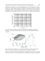
Y or in Z direction are nearly same, shown in Figure 7. The relationships between torque
and yaw angle or pitch angle of the docking mechanism are nearly same, they are shown in
Figure 8. The relationship between torque and roll angle of the docking mechanism are
shown in Figure 9. Above figures indicates the complexity of the dynamics characteristics of
docking mechanism.
-0.01 0 0.01 0.02
-10000
-5000
0
5000
Force, N
Displacement,
m
Fig. 6. Force and displacement in X direction
-0.06 -0.04 -0.02 0 0.02 0.04 0.06
-3000
-2000
-1000
0
1000
2000
3000
Force , N
Displacement, m
Fig. 7. Force and displacement Y or Z direction
The capturing and the impact absorbing are two main successive on-orbit docking phases
for the on-ground HIL simulation (Peng et al., 1992). During the impact-absorbing phase,
the docking mechanism shows strong coupling and nonlinearity and its parameters vary in
large scale. During the capturing phase, the active docking mechanism on the chase vehicle
collisions with the passive docking mechanism mounted on the target vehicle and the
contact cases are very complicate (Guan, 2001). So it is difficult to describe the actual
docking mechanism with the mathematical model, or it will abate the credence of the
simulation. Thus, it is proper to use the physical model of docking mechanism, especially
use full scale to docking/berthing hardware as the physical model participating in the
simulation.
Advances in Spacecraft Technologies
10
-0.1 -0.05 0 0.05 0.1
-1000
0
1000
Torque, Nm
Revolving angle, rad
Fig. 8. Torque and angle in yaw and pitch
-0.1 -0.05 0 0.05 0.1
-300
-200
-100
0
100
200
300
Torque, Nm
Revolving angle, rad
Fig. 9. Torque and angle in roll
3.5 Dynamics model of simulated system
If the mathematic model of the docking mechanism is established, its block diagram can
connect with the block diagram of the docking dynamics model of spacecraft body. Then the
dynamics model of simulated system is established, shown in Figure 11. Its reference frame
is the body coordinate
)ZYXO(
11111
e
.
The mathematic model of the simulated system can be used to validate the correction of
real-time simulation model of the HIL simulation system.
Fig. 10. Block diagram of docking mechanism
Hardware-In-the Loop Simulation System Construction for Spacecraft
On-orbit Docking Dynamics, Ideas, Procedural and Validation
11
Dynamics
model of
spacecrafts
on-orbit
docking
Force and
torque
Model of
docking
mechnism
Postion
and pose
Mathematical
model
Mathematical
model
Fig. 11. Simulated system model
3.6 Frequency band width of docking dynamics
The rigidity in the longitudinal direction of the APAS 89 is bigger than that in other
directions. The value of the rigidity is not a constant, it varies in large-scale. But it can be
roughly divided as contacting rigidity and impact absorbing rigidity. The contacting rigidity
is nearly
6
10
N/m. Considering the mass of the spacecrafts, the frequency of the main
dynamic process needed to be re-emerging by the HIL simulation is finite. The upper
frequency bound is called as docking frequency, signed as
d
ω
and
d
ω
is usually no larger
than 5 Hz. The dynamic process of spacecraft on-orbit docking is a high frequency response
process, it requires that the motion simulator and the F/T sensor should have high
frequency response ability.
4. System construction ideas of HIL simulation for spacecraft on-orbit
docking dynamics
The dynamics model of spacecraft on-orbit docking and the actual body of docking
mechanism are two components of the HIL simulation. They come from the simulated
system, shown in Figure 12. Before the constructing of HIL simulation system, the correction
of the dynamic model of spacecrafts on-orbit docking should be verified.
Real-time simulation
Hardware
under test
Mathematical model Physical model
Fig. 12. Simulated system
The mathematic model of spacecraft on-orbit docking dynamics can run on real-time
simulation computer, but it is not stand alone. The input signals of the real-time simulation
Advances in Spacecraft Technologies
12
computer are the forces and torques values created by the docking mechanism, mean while
the real-time simulation computer outputs the movement values of the spacecraft bodies.
Obviously, the actual docking mechanisms or their physical models can not be drive by the
electrical signals created by the real-time simulation computer, and they can not provide the
electrical signals of force and torque needed by the real-time computer either.
Here, a generalized interface concept is presented. The simulation/hardware interface is a
complex system, not an electrical interface. It connects the real-time simulation with the
hard wares under test and sets up the HIL simulation system, shown in Figure 13. It may
include electro-hydraulic system, electro-mechanical system, parallel manipulator, various
sensors, and so on.
The simulation/hardware interface of the HIL simulation system for spacecraft on-orbit
docking dynamics consists of the motion simulator and the force and torque sensors. The
motion simulator accepts the motion command signals created by the real-time simulation
computer and outputs mechanical movements which can drive the docking mechanism.
Then, the active dock mechanism and passive docking mechanism can collide with each
other and produce force and torque. The force and torque sensor which is mounted on the
rack picks up the force and torque acted by the active docking mechanism. This force and
torque sensor can be imaged having been mounted between the passive docking mechanism
and the target vehicle body. The force and torque sensor which is mounted on the moving
plate of the Stewart platform picks up the force and torque acted by the passive docking
mechanism. This force and torque sensor can be imaged having been mounted between the
active docking mechanism and the chaser vehicle body. The actual forces and torques are
transformed into the digital signals which can be collected by the real-time simulation
computer. Now, the main feedback loop of the HIL simulation system is established. It is
called two force and torque sensor scheme.
Simulation/hardware interface
Real-time simulation
Hardware
under test
6 DOF motion
simulator
6 DOF
Force/Torque sensor
Hardware-In-the-Loop simulation system
Fig. 13. HIL simulation system
The dynamic characteristics of the feedback system of the HIL simulation system are
required to be similar with those of the simulated system. But unfortunately the dynamic
characteristics of the simulation/hardware interface distort the similarity, especially for the
high frequency response dynamics simulation. If the dynamic characteristics of the feedback
system are not properly rebuilt, the dynamic characteristics of the HIL simulation system
are quietly different with those of simulated system. For an example, the simulated system
is always stable, but its HIL simulation may be unstable. This is the fundamental reason of
the system design problem or system integrated problem. So the system design problems or
Hardware-In-the Loop Simulation System Construction for Spacecraft
On-orbit Docking Dynamics, Ideas, Procedural and Validation
13
system integrated problems (Chang et al., 2007a) are put forward. But the system
construction of the HIL simulation for the spacecraft on-orbit docking dynamics is difficult.
The main part of the motion simulator of the simulation/hardware interface is a Stewart
platform driven by six electro-hydraulic servo systems, it is a nonlinear and strong coupling
multi-input multi-output (MIMO) system. The dynamic model of spacecrafts on-orbit
docking is also a nonlinear and strong coupling MIMO system. Further more, the actual
docking mechanism is included into the HIL simulation, the docking mechanism is a very
complex electro-mechanical system. It may be controlled or operated by a human. So the
HIL simulation system is too complex to study as a whole system. That is why the ideas of
simulation/hardware interface of HIL simulation system for spacecraft on-orbit docking is
put forward.
The system design procedure based on the concept of the simulation/hardware interface is
illustrated in Figure 14. It is expected to find the criterion or guideline to the design of the
simulation/hardware interface, through analyzing the HIL simulation system. The guide
line of the simulation/hardware interface design can be gained through analyzing the guide
line of the HIL simulation. During system design period, design problem of the complex
HIL simulation system is simplified as a comparatively simple design problem of
simulation/hardware interface.
Simulation/hardware interface
Real-time simulation
Hardware
under test
6 DOF motion
simulator
6 DOF
Force/Torque sensor
Simulation/hardware interface
6 DOF motion
simulator
6 DOF
Force/Torque sensor
System design
Hardware-In-the-Loo
p
simulation s
y
stem
System building
System tuning
Fig. 14. HIL simulation system design, system building and system tuning
During system tuning or system building period, the object of the system tuning is
simulation/hardware interface. Through tuning the dynamic characteristics of the
simulation/hardware interface, the dynamic characteristics of the whole HIL simulation
system can be adjusted to meet the requirements of simulation.
If un-modelled dynamic characteristics are omitted, the real-time simulation and the
hardware under test do little to the authenticity of the HIL simulation based on above
system construction ideas, because they are the components of the simulated system. In
another word, above system construction ideas ensure the adaptability of the HIL
simulation system to the docking mechanism and to the spacecraft.
And this is the fundamental base that a simplified docking mechanism can be used to
validate the HIL simulation system. This is another merit of above HIL simulation system
construction ideas.
The initial capture condition and locus planning model block is added into above HIL
simulation, the basic system structure of HIL simulation for on-orbit docking is shown in
Figure 15. The locus planning programme drives the motion simulator to make the passive
docking mechanism to collide with active docking mechanism mounted on the rack with the
initial test conditions. And just before capturing, the feed back loop of the dynamics control
is closed.