Advances in Spacecraft Technologies Part 2 pdf
Bạn đang xem bản rút gọn của tài liệu. Xem và tải ngay bản đầy đủ của tài liệu tại đây (2.65 MB, 40 trang )
Advances in Spacecraft Technologies
30
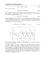
After tuning the HIL simulation system, a set of tests are done in X direction and in Y
direction respectively. The test parameters and the test results are shown in Table 4. Figure
45 and Figure 46 show the force curve and the velocity curve at 0.471Hz in X direction,
while Figure 47 and Figure 48 show the force curve and the velocity curve at 0.471Hz in Y
direction the test parameters. (Chang, 2010)
60 80 100 120
-300
-200
-100
0
100
Force, N
Time, s
Fig. 43. Force curve
60 80 100 120
-0.05
0
0.05
Ve lo c i t
y
, m/s
Time, s
Fig. 44. Velocity curve
60 65 70
-500
-250
0
250
500
Force, N
Time, s
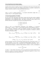
Fig. 45. Force curve
8. Conclusion
The ideas on the simulation/hardware interface are presented. The simulation/hardware
interface is a complex mechtronics system, it connects the real-time simulation with the hard
wares under test and sets up the HIL simulation system.
Hardware-In-the Loop Simulation System Construction for Spacecraft
On-orbit Docking Dynamics, Ideas, Procedural and Validation
31
The ideas of the simulation/hardware interface simplified the HIL system design and
system building. The design problem of the complex HIL simulation system is simplified as
a comparatively simple design problem of simulation/hardware interface. Through tuning
the dynamic characteristics of the simulation/hardware interface, the dynamic
characteristics of the whole HIL simulation system can be rebuilt.
60 65 70
-0.04
-0.02
0
0.02
0.04
Velocit
y
, m/s
Time, s
Fig. 46. Velocity curve
65 70 75
-500
-250
0
250
500
Force, N
Time, s
Fig. 47. Force curve
65 70 75
-0.04
-0.02
0
0.02
0.04
Time, s
Fig. 48. Velocity curve
Based on the ideas on the simulation/hardware interface, the design procedural of the HIL
simulation can be divided into following steps: the segmentation of the simulated system,
the establishing of the mathematic model, the design of the simulation/hardware interface
and the building of the whole system of HIL simulation.
The research on the single DOF HIL simulation system for spacecraft on-orbit docking
dynamics verified the correction and feasibility of the ideas and procedural of the HIL
Advances in Spacecraft Technologies
32
simulation system construction. Then the research results of single DOF HIL simulation can
be used on each degree of freedom of the MIMO HIL simulation system for spacecraft on-
orbit docking. And its validation was done on an experimental system.
Further research work may be focused on the system building theory or system synthesis
theory of multi-DOF HIL simulation for spacecraft on-orbit docking,. It is a promising
research field.
9. References
Ananthakrishnan, S.; Teders, R. & Alder, K. (1996). Role of estimation in real-time contact
dynamics enhancement of space station engineering facility. IEEE Robotics
&Automation Magazine, Sep. 1996, pp.20-27
Chang, T. L.; Cong, D. C.; Ye, Z. M. & Han, J. W. (2007a).
A new procedural for the
integration of the HIL simulation system for on-orbit docking. Proceedings of the
2007 IEEE International Conference on Integration Technology, pp.769-773, ISBN
Shenzhen Institute of Advanced Technology, Mar. 2007, IEEE, Shenzhen, China.
Chang, T. L.; Cong, D. C.; Ye, Z. M. & Han, J. W. (2007b).
Time problems in HIL simulation
for on-orbit docking and compensation. Proceedings of the 2nd IEEE Conference on
Industrial Electronics and Applications (IEEE ICIEA 2007)
,pp.841-846. IEEE
Industrial Electronics (IE) Chapter & Harbin Institute of Technology, Ma. 2007,
Harbin, China
,
Chang, T. L.; Cong, D. C.; Ye, Z. M. & Han, J. W. (2007c). Electro-hydraulic servo control
system design of HIL simulator for spacecraft on-orbit docking. Proceedings of the
Fifth International Symposium on Fluid Power Transmission and Control
(ISFP2007), Yansan University, Beidaihe, China, Jul. 2007: 580~584.
Chang, T. L.; Cong, D. C.; Ye, Z. M. & Han, J. W. (2007d).
Interface issues in Hardware-In-
the-Loop simulation for spacecraft on-orbit docking. Proceedings of the Sixth IEEE
International Conference on Control and Automation (IEEE ICCA 2007)
, IEEE
Control Systems Chapter (Singapore) & IEEE Control Systems Chapter
(Guangzhou), Guangzhou, China, Jun. 2007: 2584-2590.
Chang, T. L.; Cong, D. C.; Ye, Z. M. & Han, J. W. (2007e). Simulation on HIL ground
experimental simulator for on-orbit docking dynamics. Acta Aewnautica et
Astwanautica. Vol.28, No.4, Jul. 2007, pp.975-980( in Chinese)
Chang, T. L.; Cong, D. C.; Ye, Z. M. & Han, J. W. (2008). Research on fundamental problems
and the solutions of HIL simulation for on-orbit docking dynamics. Journal of
Astronautics. Vol.29, No.1, Jan. 2008, pp.53-55( in Chinese)
Chang, T. L. (2010). Research on verification of authenticity of HIL simulation using vibro-
impact model. Journal of Vibration and Shock. Vol.29, No.1, Jan. 2010, pp.22-25 ( in
Chinese)
Gates, R. M. & Graves, D. L. (1974). Mathematical model for the simulation of dynamic
docking test system (DDTS) active table motion. N74-33776, pp.1-3
Grimbert, D. & Marchal, P. (1987). Dynamic testing of a docking system. N88-19516, pp.281-
288
Hardware-In-the Loop Simulation System Construction for Spacecraft
On-orbit Docking Dynamics, Ideas, Procedural and Validation
33
Guan, Y. Z.(2001). Research on dynamics and simulation technique of spacecraft docking
process. Ph. D. thesis. Harbin, China: Harbin Institute of Technology, Aug. 2001,
pp.8-12 (in Chinese)
He, J. F.(2007). Analysis and control of hydraulically driven 6-DOF parallel manipulator. Ph.
D. thesis. Harbin, China: Harbin Institute of Technology, Feb. 2007, pp.89-98 (in
Chinese)
Huang, Q. T.; Jiang, H. Z.; Zhang, S. Y. & Han, J. W. (2005). Spacecraft docking simulation
using HIL simulator with Stewart platform. Journal of Chinese Mechanical
Engineering. Vol.18, No.3, Mar. 2005, pp.415-418
Kang, J.; Guan, H. H. & Song, J.(1999). Study on dynamics of mechano-electronic spring-
damper system with differential connections. J. Tsinghua Univ. (Sci. & Tech.)
Vol.39, No.8, Aug. 1999, pp.68-71
Kawabe, H.; Inohira, E.; Kubota, T.; Uchiyama, M. (2001). Analytical and experimental
evaluation of impact dynamics on a high-speed zero G motion simulator.
Proceedings of the 2001 IEEE/RSJ International Conference on Intelligent Robots
and Systems. Hawaii, USA, Oct. 2005, pp.39~45.
Lange, C.; Martin, E.; Piedboeuf, J. C.; Kovecses, J. (2002). Towards Docking Emulation
Using Hardware in the Loop Simulation with Parallel Platform. Proceedings of the
Workshop on Fundamental Issues and Future Directions for Parallel Mechanisms
and Manipulators. Quebec, Canada, Oct. 2002, pp.1-4
Lim, G. K.; Freeman, R. A.; Tesar, D. (1989). Modelling and Simulation of a Stewart Platform
Type Parallel Structure Robot. The University of Texas at Austin, 1989, pp.1-151
Merlet, J. P. (2000). Parallel robots. Dordrecht: Kluwer Academic Publishers, 2000.
Merrit, H.E. (1967). Hydraulic control systems. New York: Wiley, 1967
Monti, A.; Figueroa, H.; Lentijo, S.; Wu, X. & Dougal, R. (2005). Interface issues in
Hardware-in-the-Loop simulation. Proceedings of the 2005 IEEE Ship Technologies
Symposium, Jul. 2005, pp.39-45
Office of Naval Research's Best Manufacturing Practices. (1999). Report of survey conducted
at NASA Marshall Space Flight Center. Best Manufacturing Practice Center of
Excellence. Huntsville, USA, Apr. 1999, pp.12-13
Peng, C. R.; Qu, G. J.; Ma, Z. C. & Yu, J. Y. (1992). Russia large spacecraft dynamics and its
testing technology. Spacecraft Engineering, No.3, Mar.1992, pp.1-7 (in Chinese)
Tian, H.; Zhao, Y. & Zhang, D. W. (2007). Movement simulator modelling and simulation in
integrate test platform for docking mechanism. Journal of Astronautics. Vol.28,
No.4, July 2007, pp.996-1001( in Chinese)
Wu, L. B.; Wang, X. Y. & Li, Q. (2008). Fuzzy-immune PID control of a 6-DOF parallel
platform for docking simulation. Journal of Zhejiang University (Engineering
Science). Vol.42, No.3, Mar.2008, pp.387-391( in Chinese)
Yan, H.; Ye, Z. M.; Cong, D. C.; Han, J. W. & Li, H. R. (2007). Space docking hybrid
simulation prototype experiment system. Chinese Journal of Mechanical
Engineering. Vol.43, No.9, Sep.2007, pp.51-56( in Chinese)
Yu, W.; Yang, L. & Qu, G. J. (2004). Dynamics analysis and simulation of spacecraft docking
mechanism. Journal of Dynamic and Control, Vol.2, No.2, Feb.2004, pp. 38-42 (in
Chinese)
Advances in Spacecraft Technologies
34
Zhang, C. F. (1999). Study on Six-Degree-of-Freedom simulation for docking. Aerospace
Control, No.1, Jan. 1999, pp.70-74 (in Chinese)
Zhang, S. Y. (2006). Research on force control of hydraulic driven 6-DOF parallel robot. Ph.
D. thesis. Harbin, China: Harbin Institute of Technology, Apr. 2006, pp.6-7 (in
Chinese)
Zhao, H. & Zhang, S. Y. (2008). Stability analysis of the whole dynamics simulation system
of space docking. J. of Wuhan Uni. of Sci. & Tech. (Natural Science Edition) Vol.31,
No.1, Feb.2008, pp.87-97( in Chinese)
Zhao, Y; Tian, H. & Wang, Q. S. (2007). Analysis of dynamometry scheme for semi-physical
simulation platform of space docking mechanism. Advances in Engineering
Software. Vol.38, 2007, pp.710-716
2
Solar Sailing: Applications and
Technology Advancement
Malcolm Macdonald
Advanced Space Concepts Laboratory
University of Strathclyde, Glasgow
Scotland, E.U.
1. Introduction
Harnessing the power of the Sun to propel a spacecraft may appear somewhat ambitious and
the observation that light exerts a force contradicts everyday experiences. However, it is an
accepted phenomenon that the quantum packets of energy which compose Sunlight, that is to
say photons, perturb the orbit attitude of spacecraft through conservation of momentum; this
perturbation is known as solar radiation pressure (SRP). To be exact, the momentum of the
electromagnetic energy from the Sun pushes the spacecraft and from Newton’s second law
momentum is transferred when the energy strikes and when it is reflected. The concept of
solar sailing is thus the use of these quantum packets of energy, i.e. SRP, to propel a spacecraft,
potentially providing a continuous acceleration limited only by the lifetime of the sail
materials in the space environment. The momentum carried by individual photons is
extremely small; at best a solar sail will experience 9 N of force per square kilometre of sail
located in Earth orbit (McInnes, 1999), thus to provide a suitably large momentum transfer the
sail is required to have a large surface area while maintaining as low a mass as possible.
Adding the impulse due to incident and reflected photons it is found that the idealised thrust
vector is directed normal to the surface of the sail, hence by controlling the orientation of the
sail relative to the Sun orbital angular momentum can be gained or reduced. Using
momentum change through reflecting such quantum packets of energy the sail slowly but
continuously accelerates to accomplish a wide-range of potential missions.
1.1 An historical perspective
In 1873 James Clerk Maxwell predicted the existence of radiation pressure as a consequence
of his unified theory of electromagnetic radiation (Maxwell, 1873). Apparently independent
of Maxwell, in 1876 Bartoli demonstrated the existence of radiation pressure as a
consequence of the second law of thermodynamics.
The first experimental verification of the existence of radiation pressure and the verification
of Maxwell's results came in 1900. At the University of Moscow, Peter Lebedew succeeded
in isolating radiation pressure using a series of torsion balance experiments (Lebedew,
1902). Nichols and Hull at Dartmouth College, New Hampshire, obtained independent
verification in 1901 (Nichols & Hull, 1901, 1903).
Around this period a number of science
fiction authors wrote of spaceships propelled by mirrors, notably the French authors Faure
and Graffigny in 1889. However, it was not until the early 20
th
century that the idea of a
Advances in Spacecraft Technologies
36
solar sail was accurately articulated. Solar sailing as an engineering principle can be traced
back to the Father of Astronautics, Ciołkowski (translated as Tsiolkovsky) and Canders
(translated as Zander or Tsander) (Ciołkowski, 1936; Tsander, 1924).
There is some
uncertainty regarding the dates of Ciołkowski’s writings on the potential use of photonic
pressure for space propulsion. However, it is known that he received a government pension
in 1920 and continued to work and write about space. It is within the early part of this
period of his life, in 1921 perhaps, which he first conceived of space propulsion using light.
Upon the publication of the works of Herman Oberth in 1923, Ciołkowski’s works were
revised and published more widely, enabling him to gain his due international recognition.
Inspired by Ciołkowski, Canders in 1924 wrote “For flight in interplanetary space I am working
on the idea of flying, using tremendous mirrors of very thin sheets, capable of achieving favourable
results.” (Tsander, 1924). Today this statement is widely, though not universally, bestowed
the credit as the beginning of solar sailing as an engineering principle.
In 1923 the German rocket pioneer Herman Julius Oberth proposed the concept of reflectors
in Earth orbit (Spiegelrakete, or Mirror rocket) to illuminate northern regions of Earth and
for influencing weather patterns (Oberth, 1923). It was this work which caused the works of
Ciołkowski to be revised and published more widely. In 1929 Oberth extended his earlier
concept for several applications of orbit transfer, manoeuvring and attitude control
(Spiegelführung, or Mirror guidance) using mirrors in Earth orbit (Oberth, 1929). This work
has a clear parallel with that of Canders’ from 1924. However, it is also of interest that in this
work Oberth noted solar radiation pressure would displace the reflector in a polar orbit in
the anti-Sun direction. Thus, with the central mass, i.e. Earth, displaced from the orbit plane
Oberth had, in-effect, noted the application of solar sailing to what we now call Highly Non-
Keplerian Orbits and which will be discussed later in Section 3.1.2.
Following the initial work by Ciołkowski, Canders and Oberth the concept of solar sailing
appears to have remained largely dormant for over thirty years. In the 1950s the concept
was re-invigorated and published once again in popular literature, this time in North
America. The first American author to propose solar sailing appears to have been the
aeronautical engineer Carl Wiley, writing under the pseudonym Russell Sanders to protect
his professional credibility (Wiley, 1951).
Wiley discussed the design of a feasible solar sail
and strategies for orbit raising in some technical detail. In particular he noted that solar sails
could be “tacked” allowing a spiral inwards towards the Sun. In 1958 Richard Garwin, then
at the IBM Watson laboratory of Columbia University, authored a solar sail paper in the
journal Jet Propulsion where he coined the term “solar sailing” (Garwin, 1958).
Subsequent to the discussion of solar sailing by Garwin, more detailed studies of the orbits
of solar sails were undertaken during the late 1950s and early 1960s (Birnbaum, 1968; Cotter,
1959; Fimple; 1962; Gordon, 1961; London; 1960; Norem, 1969; Sands, 1961; Tsu, 1959). For a
fixed sail orientation several authors have shown that solar sail heliocentric orbits are of the
form of logarithmic spirals (Bacon, 1959; London, 1960).
Early comparisons of solar sailing with chemical and ion propulsion systems showed that
solar sails could match or out perform these systems for a range of mission applications,
though of course the level of assumed technology status is crucial in such comparisons
(MacNeal, 1972). These early studies explored the fundamental problems and benefits of
solar sailing, but lacked a specific mission to drive detailed analyses and to act as a focus for
future utilisation. In the early 1970’s the development of the Space Shuttle and the
technological advances associated with deployable structures and thin films suggested that
perhaps solar sailing was ready to move beyond paper studies (Cotter, 1973; Grinevitskaia;
Solar Sailing: Applications and Technology Advancement
37
1973; Lippman, 1972; MIT Student Project, 1972). In 1974 NASA funded a low-level study of
solar sailing at the Battelle laboratories in Ohio which gave positive recommendations for
further investigation (Wright, 1974).
The Battelle laboratories recommendations were acted
upon at NASA-JPL in an Advanced Mission Concepts Study for Office of Aeronautics and
Space Technology (OAST) in FY1976 (Uphoff, 1975). During the continuation of the Battelle
laboratories study Jerome Wright discovered a trajectory that would allow a relatively high-
performance solar sail to rendezvous with comet Halley at its perihelion in the mid-1980’s
by spiralling towards the Sun and then changing the orbit inclination by almost 180 deg
(Wright & Warmke, 1976).
The flight time of four years would allow for a late 1981 or early
1982 launch, however the required level of solar sail
1
performance suggests the study was
always over optimistic. Furthermore, as it turns out the first operational space shuttle flight
did not occur until the November of 1982 (STS-5); as such, the shuttle could not have acted
as the Comet Halley solar sail launch vehicle as had been originally envisaged. A seven to
eight year mission had been envisaged using solar-electric ion propulsion, requiring a
launch as early as 1977. These positive results prompted NASA-JPL to initiate an
engineering assessment study of the potential readiness of solar sailing, following which a
formal proposal was put to NASA management on 30 September 1976. At the same time a
companion study and technology development program for Advanced Solar Electric
Prolusion was initiated in order to allow it to be evaluated as a competitor for the Halley
mission. During the initial design study an 800-m per side, three-axis stabilised, square solar
sail configuration was envisaged, but then dropped in May 1977 due to the high risks
associated with deployment of such a massive structure. The design work progressed to
focus on a spin stabilised heliogyro configuration. The heliogyro concept, which was to use
twelve 7.5 km long blades of film rather than a single sheet of sail film, had been developed
by Richard MacNeal and John Hedgepath (Hedgepath & Benton, 1968; MacNeal, 1967).
The
heliogyro could be more easily deployed than the square solar sail by simply unrolling the
individual blades of the spinning structure. As a result of this design study the structural
dynamics and control of the heliogyro were characterised and potential sail films
manufactured and evaluated (Friedman et al, 1978; MacNeal, 1971).
As a result of the
Advanced Solar Electric Prolusion companion study NASA selected the Solar Electric
Propulsion (SEP) system in September 1977 upon its merits of being a less, but still
considerable risk for a comet Halley rendezvous (Sauer, 1977).
A short time later the SEP
rendezvous mission was also dropped due to escalating cost estimates (Logsdon, 1989).
1.2 Recent technology developments and activities
Following the Comet Halley studies solar sailing entered a hiatus until the early 1990’s
when further advances in spacecraft technology led to renewed interest in the concept. The
first ever ground deployment of a solar sail was performed in Köln in December 1999 by the
German space agency, DLR, in association with ESA and INVENT GmbH when they
deployed a square 20-m solar sail, shown in Fig. 1 (Leipold et al, 2000; Sebolt et al, 2000).
This ground deployment and the associated technology developed by DLR and ESA has
struggled to progress to flight, initially an in-orbit deployment was planned for 2006
however this project floundered, with a similar, but smaller, demonstration now planned for
2013 as part of a three-step solar sail technology development program (Lura et al, 2010).
1
The comet Halley solar sail had a required characteristic acceleration of 1.05 mm s
-2
; see Wright, 1992
(pp. 42).
Advances in Spacecraft Technologies
38
In 2005 NASA completed dual solar sail development programs, funding a solar sail design
by ATK and another by L’Garde Inc. who used the inflatable boom technology developed
under the IAE program. Both solar sail systems were deployed to 20-m (side length) in the
large vacuum chamber at NASA Glenn Research Center's Space Power Facility at Plum
Brook Station in Sandusky, Ohio, U.S.A, the world's largest vacuum chamber
(Lichodziejewski et al, 2003; Murphy et al, 2003 & 2004). Following the deployment
demonstrations the L’Garde design was down-selected due to its perceived scalability to
much larger sail sizes for the subsequent NASA New Millennium Space Technology 9 (ST-9)
proposal, prior to the ST-9 program being cancelled. However, it should be noted that the
ATK sail was considered a lower risk option. The intention of the NASA funding was to
develop solar sail technology to Technology Readiness Level (TRL) six, however a
subsequent assessment found that actually both the L’Garde and ATK sail failed to fully
achieve either TRL 5 or 6, with the ATK sail achieving 89% and 86%, respectively and the
L’Garde sail reaching 84 % and 78 %, respectively (Young et al, 2007).
In May 2010 the first spacecraft to use solar radiation pressure as its primary form of
propulsion was launched by the Japanese space agency, JAXA, onboard an H-IIA launch
vehicle from the Tanegashima Space Center as an auxiliary payload alongside the Japanese
Venus orbiter Akatsuki, formerly known as the Venus Climate Orbiter (VCO) and Planet-C,
and four micro-spacecraft. The solar sail spacecraft is called IKAROS (Interplanetary Kite-craft
Accelerated by Radiation Of the Sun) and like the Akatsuki spacecraft was launched onto a
near-Venus transfer trajectory. The IKAROS is a square solar sail, deployed using spinning
motion and 0.5 kg tip masses, the polyimide film used for solar sailing also has thin-film solar
arrays embedded in the film for power generation and liquid crystal devises which can, using
electrical power, be switched from diffusely to specularly reflective for attitude control (Mori
et al, 2010). IKAROS has demonstrated a propulsive force of 1.12mN (Mori et al, 2010) and is
shown in Fig. 3. The IKAROS mission is envisaged as a technology demonstrated towards a
power sail spacecraft, using the large deployable structure to host thin-film solar cells to
generate large volumes of power to drive a SEP system (Kawaguchi, 2010).
In addition to the traditional view of solar sailing as a very large structure several
organisations, including NASA and the Planetary Society, are developing CubeSat based
solar sails. Indeed, NASA flew the first CubeSat solar sails on board the third SpaceX Falcon
1 launch on 2 August 2008 which failed approximately 2 minutes after launch. It is however
unclear how such CubeSail programs will complement traditional solar sailing and whether
they will provide sufficient confidence in the technology to enable larger, more advanced
solar sail demonstrator missions. It is clear that the technology of solar sailing is beginning
to emerge from the drawing board. Additionally, since the NASA Comet Halley mission
studies a large number of solar sail mission concepts have been devised and promoted by
solar sail proponents. As such, this range of mission applications and concepts enables
technology requirements derivation and a technology application pull roadmap to be
developed based on the key features of missions which are enabled, or significantly
enhance, through solar sail propulsion. This book chapter will thus attempt to link the
technology application pull to the current technology developments and to establish a new
vision for the future of solar sailing.
2. Performance metrics
To compare solar sail mission applications and concepts standard performance metrics will be
used. The most common metric is the characteristic acceleration which is the idealised SRP
Solar Sailing: Applications and Technology Advancement
39
acceleration experienced by the solar sail facing the Sun at a distance of 1 au. An ideal or
perfect sail facing the Sun at a distance of 1 au will experience a pressure of 9.126 µN m
-2
;
however, in practise an efficiency factor must be added to this to account for non-ideal
performance (Wright, 1992). The sail characteristic acceleration offers an excellent performance
metric unsullied by difficulties in hardware development and implementation of the theory.
Fig. 1. DLR solar sail ground deployment test. Image credit DLR
Fig. 2. 20-m solar sail deployment tests by ATK (left) and L’Garde (right) at NASA Glenn
Research Center's Space Power Facility at Plum Brook Station. Image credit NASA
Fig. 3. IKAROS solar sail, imaged by free flying camera. Image credit JAXA
Advances in Spacecraft Technologies
40
The sail assembly loading is the primary hardware performance metric for a solar sail,
allowing a measure of the performance of the sail film and the efficiency of the solar sail
architectural and structural design. The sail characteristic acceleration and assembly loading
are defined as,
2
,
(/)
c
S
SS
Sa
m
P
a
mA A
σ
σ
==
+
(1)
where, P is SRP acting on the solar sail, m
a
is mass attached to the solar sail, m
s
is mass of the
solar sail and A is the reflective surface area of the solar sail, typically assumed simply as the
sail film area.
3. Solar sail mission catalogue
In the final quarter of the 20
th
century and opening decade of the 21
st
century solar sail
propulsion has been proposed for a diverse range of mission applications ranging
throughout the solar system. However, in-order to develop an application-pull technology
development roadmap the concepts which are truly enabled or significantly enhance by
solar sail propulsion must be identified. As such the mission catalogue will initially consider
a wide range of mission concepts to allow definition of key characteristics of missions which
are truly enabled or significantly enhance by solar sail propulsion. Subsequently critical
missions which can act as facilitators to later, more technologically complex missions will be
discussed in further detail. Through these considerations a solar sail application-pull
technology development roadmap is established, using each mission as a technology
stepping-stone to the next.
3.1 Identification of key characteristics
To aid the identification of key characteristics solar sail applications are divided into the
seven categories below.
3.1.1 Planet-centred and other short orbit period applications
This category is essentially planet, minor-planet and small body centred trajectories. Planet-
centred trajectory design has been largely restricted to escape manoeuvres or relatively
simplistic orbit manoeuvring, such as lunar fly-by’s or orbit inclination change (Eguchi et al,
1993; Fekete et al, 1992; Fimple, 1962; Green, 1977; Irving 1959; Lawden, 1958; Leipold, 1999;
Macdonald, 2005a, 2005b; Morgan, 1979; Pagel, 2002; Sackett, 1977; Sackett & Edelbaum, 1978;
Sands, 1961). Such trajectories place significant technology demands on the solar sail
architecture, for example a locally optimal energy gain control profile for an Earth-centred
orbit requires the sail to be rotated through 180 degrees once per orbit and then rapidly reset to
maximise energy gain; as the sail size grows clearly this becomes an increasingly demanding
technology requirement. It is noted that other simplistic orbit manoeuvres require similarly
agile sail technology, for example an orbit plane-change require the sail to be rotated
approximately 70.5 deg. twice per orbit (Macdonald, 2005a). This technology requirement for
an agile sail is a significant disadvantage to the majority of short orbit period solar sail
applications; however it should not be considered a blockage on the roadmap.
Two highly significant planet-centred solar sail applications have been identified which do
not require, but may in-practise desire, active sail control and hence do not require an agile
Solar Sailing: Applications and Technology Advancement
41
sail; these are the GeoSail concept (Leipold et al, 2010; Macdonald & M
c
Innes, 2000;
Macdonald et al, 2007a) and the Mercury Sun-Synchronous Orbiter (Leipold et al, 1996a,
1996b). These two solar sail mission concepts are very similar, both using a solar sail with
fixed attitude to independently vary a single orbit parameter due to the orbits shape and
alignment with the primary body, and the alignment to the Sun, creating a non-inertial
orbit. GeoSail rotates the argument of perigee of an eccentric orbit within the ecliptic plane
at approximately 1 deg per day such that orbit apogee remains within the Earth’s
magnetotail. The Mercury Sun-Synchronous Orbiter meanwhile rotates the ascending node
of an eccentric orbit whose orbit plane is at right-angles to the ecliptic plane such that the
orbit plane remains perpendicular to the Sun-planet line, therefore enabling a sun-
synchronous orbit at Mercury which is not possible naturally due to the high reciprocal of
flattening of the planet.
3.1.2 Highly non-keplerian orbit applications
This category is, in some regards, an extension of the concept embodied by non-inertial
orbits, with the sail providing a small but continuous acceleration to enable an otherwise
unattainable or unsustainable observation outpost to be maintained.
Interestingly, as early as 1929 Oberth, in a study of Earth orbiting reflectors for surface
illumination (Oberth, 1929), noted that solar radiation pressure will displace a reflector in a
polar orbit in the anti-Sun direction. Since then a significant volume of work has been
performed in this area; a comprehensive review of Highly Non-Keplerian Orbits (NKO) has
recently been completed by M
c
Kay et al (2010) in which a range of orbits and applications
are presented. Highly NKOs are typically characterised as requiring a small but continuous
acceleration in a fixed direction, in this case provided by a solar sail with fixed attitude to
provide the thrust required to compensate for the differences in gravitation and rotational
force (gravity gradient) to displace the spacecraft to an artificial equilibrium point at a
location some distance from a natural libration point.
Two primary solar sail applications of Highly NKOs are found in the literature; Geostorm
and Polesitter (also called Polar Observer) (Biggs & M
c
Innes, 2009; Chen-wan, 2004; Driver,
1980; Forward, 1991; Matloff, 2004; M
c
Innes et al, 1994; Sauer, Jr., 2004; Waters & M
c
Innes,
2007; West, 1996, 2000, 2004). The Geostorm mission concept provides real-time monitoring
of solar activity; the spacecraft would operate sunward of the Earth’s L
1
point, thus
increasing the warning time for geomagnetic storms. By imparting a radial outward force
from the Sun the solar radiation pressure in-effect reduces solar gravity and allows the L
1
point to be moved sunward. As sail performance is increased solar gravity is further
‘reduced’, thus providing enhanced solar storm warning.
The Polesitter concept extends the Geostorm concept from a singular equilibrium point to
derive equilibrium surfaces which extend out of the ecliptic plane and are again
parameterised by the sail performance (M
c
Innes et al, 1994). By extending the artificial
equilibrium points out of the ecliptic plane, the small but continuous acceleration allows a
spacecraft to be stationed above, or below, the second body within the 3-body problem. A
further example of a highly non-keplerian orbit application is the Statite proposed by
Forward (1991), which would use a high-performance solar sail to directly balance the solar
gravity to hover stationary over the poles of the Sun.
The conceptually simple nature of the Geostorm and Polesitter missions is complicated by
mission requirements, risk and budget factors and by the unstable nature of artificial
equilibrium points. Although station-keeping should be possible (Biggs & M
c
Innes, 2009;
Advances in Spacecraft Technologies
42
Chen-wan, 2004; Sauer, Jr., 2004; Waters & M
c
Innes, 2007) the requirement to station-keep
increases the minimum level of technology requirement of the mission beyond, for example,
the GeoSail mission discussed previously.
3.1.3 Inner solar system rendezvous missions
This category covers missions which use the solar sail to rendezvous, and perhaps bound
the orbit to, a body in the inner solar system; defined as all bodies from the asteroid belt
inwards, specifically excluding bodies which are, in-effect, part of the Jupiter system, for
example the Hilda and Jupiter Trojan asteroids.
The use of solar sails for high-energy sample return missions to the inner planets has been
discussed extensively within the literature (Garner et al, 2001; Hughes, 2006; Leipold, 1999;
McInnes et al, 2002; Sauer, Jr., 1976; Tsu, 1959; Vulpetti et al 2008; Wright, 1992; Wright &
Warmke, 1976) often without presenting the trajectory as part of a larger system-level trade
on the propulsion selection criteria. Solar sailing, like other forms of low-thrust propulsion,
requires that if a bound orbit about the target body is desired then at arrival the spacecraft
must have, in-effect, zero hyperbolic excess velocity. Therefore, any wholly low-thrust
interplanetary mission is required, unlike high-thrust missions, to slow-down prior to arrival
at the target body and subsequently the transfer duration is typically significantly increased;
this is especially true for bodies which can be relatively easily reached by high-thrust,
chemical propulsion systems such as Mars and Venus. Furthermore, once the solar sail has
been captured into a bound-orbit about the target body it then has the typical disadvantages
discussed previously for planet-centred solar sail applications.
A sequence of assessment studies was previously conducted by the Authors and Hughes
looking at solar sail sample return missions to Mars (M
c
Innes et al, 2003a), Venus (M
c
Innes
et al, 2003b), Mercury (Hughes, 2006; M
c
Innes et al, 2003c), and a small-body (M
c
Innes et al,
2003d), with the specific objective of enabling a system-level trade on the propulsion
selection criteria within each mission. Within each of these a complete system level analysis
was performed, considering a range of mission architectures, attempting to define the most
preferential solar sail architecture. The identified preferential solar sail architecture was then
compared against alternative propulsion systems conducting a similar mission.
In all Mars Sample Return mission architectures it was found to be very difficult to justify
the use of a solar sail due to the significantly increased mission duration (M
c
Innes et al,
2003a). The “grab-and-go” architecture, identified as the most preferential for solar sailing
required a mission duration of 5 – 6 years depending on the launch vehicle, while a similar
all chemical propulsion mission could be completed in only 2 years, although requiring a
slightly larger launch vehicle (M
c
Innes et al, 2003a). A very similar scenario was found in the
analysis of the Venus Sample Return mission (M
c
Innes et al, 2003b). However, it was found
that due to the increased launch mass sensitivity to returned mass the use of a solar sail for
the Earth return stage offered potential real benefits; note the solar sail attached mass for
this scenario was 323 kg requiring a sail of less than 100-m side length at an assembly
loading of 6 gm
-2
, with 20 % design margin. It was found that using a solar sail for the Earth
return stage of a Venus Sample Return mission reduced the launch mass by approximately
700 kg, enabling a smaller, hence lower cost, launch vehicle to be used without notably
impacting mission duration. Such a scenario does however have the typical disadvantages
discussed previously for planet-centred solar sail applications when using the sail to escape
the Venus gravity-well.
Solar Sailing: Applications and Technology Advancement
43
Considering both the Mercury and Small Body Sample Return missions it was found that
due to the high-energy nature of the transfer trajectories only low-thrust propulsion systems
offered viable mission concepts, with solar sailing offering potential benefits (Hughes, 2006;
M
c
Innes et al, 2003c, 2003d). Note the small-body target was asteroid 2001 QP153, with an
orbit inclination of 50 deg. The Mercury Sample Return mission would have the typical
disadvantages discussed previously for Short Orbit Period solar sail applications, however it
was found that a large, high-performance solar sail would offer some potential benefits to
such a mission (Hughes, 2006). It is of note that missions to small bodies, such as asteroid
2001 QP153, could negate the disadvantages discussed previously for short orbit period
solar sail applications as the sail may not be required to enter a bound orbit about the small-
body, if indeed a stable orbit could even be found.
3.1.4 Outer solar system rendezvous missions
The use of solar sails for outer solar system rendezvous missions has been long discussed
within the literature (Garner et al, 2001; Leipold, 1999; Wright, 1992; Wright & Warmke,
1976). Furthermore, an assessment study was previously conducted by the Authors and
Hughes looking at a range of solar sail Jupiter missions (M
c
Innes et al, 2003e, 2004a),
including concepts for exploration of the Galilean moons. As with low-thrust inner solar
system rendezvous missions the hyperbolic excess velocity at the target outer solar system
body must be lower than high-thrust missions. The inverse squared variation in SRP with
solar distance however means that the sail performance is significantly reduced over the
same sail at Earth. As such the requirement to reduce the hyperbolic excess velocity prior to
arrival at the outer solar system body leads to prolonged transfer durations. Note however
that due to the large moons within both the Jupiter and Saturn planetary systems capture
can be performed using gravity assist manoeuvres to enable the hyperbolic excess velocity
to be significantly greater than zero (Macdonald, 2005c). Furthermore, the duration required
to reduce the orbit altitude following capture is also significantly prolonged due to the
inverse squared variation in SRP with solar distance. Clearly, this class of mission becomes
increasingly unattractive as the target body moves further from the Sun.
Outer solar system rendezvous missions are concluded to be unsuitable for solar sail
propulsion due to the inverse squared variation in SRP with solar distance.
3.1.5 Outer solar system flyby missions
Outer solar system fly-by missions remove the requirement to reduce the hyperbolic excess
velocity prior to arrival at the target body and as such negate much of the negative elements
of solar sail outer solar system rendezvous missions. A Jupiter atmospheric probe mission
was considered by the Authors and Hughes (M
c
Innes et al, 2003e) as a potential Jupiter
flyby mission. It was concluded that due to the mass of the atmospheric probes, of which
three were required, and the relative ease of such a mission with chemical propulsion that
solar sail propulsion offered little to such a mission. It is of note that as the target flyby body
moves further from the Sun, and hence the difficulty of such a mission with chemical or SEP
increases, solar sail propulsion becomes increasingly beneficial; ultimately leading to a peak
in solar sail benefits for such missions in the Beyond Neptune category which will be
discussed later.
3.1.6 Solar missions
Most previous missions to study the Sun have been restricted to observations from within
the ecliptic. The Ulysses spacecraft used a Jupiter gravity assist to pass over the solar poles,
Advances in Spacecraft Technologies
44
obtaining field and particle measurements but no images of the poles. Furthermore, the
Ulysses orbit is highly elliptical, with a pole revisit time of approximately 6 years. It is
desired that future solar analysis be performed much closer to the sun, as well as from an
out-of-ecliptic perspective. The Cosmic Visions mission concept Solar Orbiter intends to
deliver a science suite of order 180 kg to a maximum inclination of order 35 deg with respect
to the solar equator and to a minimum solar approach radius of 0.22 au using SEP. The
inability of the Solar Orbiter mission to attain a solar polar orbit highlights the difficulty of
such a goal with conventional propulsion. It has however been shown that a mid-term solar
sail can be used to deliver a spacecraft to a true solar polar orbit in approximately five-years
(Goldstein et al, 1998; Macdonald et al, 2006). The Solar Polar Orbiter (SPO) mission concept
is a good example of the type of high-energy inner-solar system mission which is enabled by
solar sail propulsion.
3.1.7 Beyond Neptune
A significant quantity of work in the past decade has been performed to assess the problem
of trajectory and system design of a solar sail mission beyond Neptune (Colasurdo &
Casalino, 2001; Dachwald, 2004a, 2004b, 2005; Garner et al, 2000, 2001; Leipold & Wagner,
1998; Leipold, 1999; Leipold et al, 2006, 2010b; Lyngvi et al, 2003, 2005a, 2005b; Macdonald et
al, 2007b, 2010; M
c
Innes, 2004b; Sauer, Jr., 2000; Sharma & Scheeres, 2004; Sweetser & Sauer,
Jr., 2001; Vulpetti, 1997, 2002; Wallace, 1999; Wallace et al, 2000; West, 1998; Yen, 2001). It has
been shown that solar sail propulsion offers significant benefits to missions concepts which
aim to deliver a spacecraft beyond Neptune, for either a Kuiper Belt or Interstellar
Heliopause (at approximately 200 au) mission. Such outer solar system missions initially
exploit the inverse squared variation in SRP with solar distance by approaching the Sun to
gain a rapid energy boast which generates a hyperbolic trajectory and allows the spacecraft
to rapidly escape the solar system.
Solar sails mission concepts significantly beyond the Interstellar Heliopause were considered
by Macdonald et al (2010). In-order to determine the limit of the solar sail concept an Oort
cloud mission was examined using solely SRP to propel the spacecraft. It was found that
although no fundamental reason existed why such a mission may not be possible the
practicalities were such that the Interstellar Heliopause Probe (IHP) mission concept could be
considered representative of the upper limiting bound of the solar sail concept.
3.1.8 Key characteristics
Solar sailing has traditionally been perceived as an enabling technology for high-energy
missions; however, as has been shown in the preceding sections the key characteristics of a
mission which is enabled, or significantly enhanced by solar sailing are more complex than
simply this.
Solar sailing is, due to the lack of propellant mass, often noted as reducing the launch mass
of an equivalent chemical or SEP concept, which is in-turn noted as reducing launch and
mission cost. However, while it is accurate that the launch mass is typically reduced this
does not directly result in a reduced launch vehicle cost as the reduction may not be
sufficient to allow the use of a less capable, and hence lower cost, launch vehicle. As such
the launch cost is only reduced if the reduced launch mass allows a smaller launch vehicle
to be used, meaning that launch cost varies as a step function while launch mass linearly
increases. Finally, it should be noted that if the total mission cost is high, say, 500+ M€ then
Solar Sailing: Applications and Technology Advancement
45
reducing the launch mass cost by 10 – 20 M€ is a cost saving of order 2 – 4 %, which may not
be considered a good cost/risk ratio for the project and indeed, the cost saving may be
insufficient to pay for the additional development of the technology. Thus for the reduction
in launch mass to be an enabling, or significantly enhancing aspect of a solar sail mission
concept the cost saving must also be a significant percentage of the total mission cost.
All solar sail mission concepts can be sub-divided into two classes, these are:
• Class One
• Where the solar sail is used to reach a high-energy target and after which the sail
can be jettisoned by the spacecraft, for example the Solar Polar Orbiter mission.
• Class Two
• Where the solar sail is required to maintain a novel or otherwise unsustainable
observation outpost, for example, highly non-keplerian or non-inertial orbit
applications, such as Geostorm and GeoSail.
This distinction is important as the later compares very favourably against most other
propulsion systems, especially as the mission duration and hence reaction mass is increased.
However, a solar sail is a very large structure and could adversely impact the mission
objectives either through a characteristically low pointing accuracy due to low frequency
structural flexing, or due to the solar sail interfering with the local environment in, for
example, particle and field measurements. Thus, a critical requirement on early solar sail
demonstration missions must be to validate the simulated pointing accuracy of the platform
and the effect of the sail on the local space environment.
From the mission catalogue it is seen that solar sail propulsion has been considered for a
large range of mission applications, some of which it is more suitable for than others. Each
of the solar sail applications within the mission catalogue are sub-divided by the level of
enhancement offered by solar sail propulsion in Table 1. From Table 1 the key positive and
negative characteristics of solar sail missions are defined in Table 2.
Enabled or Significantly
Enhance
Marginal benefit No benefit
Non-Inertial Orbits, such as
GeoSail or a Mercury Sun-
Synchronous Orbiter
Venus escape at end of
sample return mission
Planetary escape at start of
mission
Highly Non-Keplerian Orbits
such as Geostorm and
Polesitter
Mercury and high-energy
small body Sample Return
missions
Mars missions
Kuiper-Belt fly-through
Outer solar system planet
fly-by
Outer solar system
rendezvous and centred
trajectories
Solar Polar Orbiter
Transit of Gravitational Lens
region
Loiter at the Gravitational
Lens
Interstellar Heliopause Probe Oort Cloud
Table 1. Solar sail missions by benefit
Advances in Spacecraft Technologies
46
Positive Characteristic Negative Characteristic
Very High Energy transfer trajectory Mars and Venus rendezvous
Inner Solar System Outer Solar System rendezvous
Highly Non-Keplerian and Non-Inertial
orbits
Short orbit period with rapid slew
manoeuvres
Final stage in a multi-stage system High radiation environment
Fly-by beyond the orbit of Neptune High pointing stability required
Required to rendezvous with a passive body
Fly-by beyond solar gravitational lens
Table 2. Solar sail mission key characteristics
3.2 Key missions
Three key mission will be briefly discussed, one from each of near, mid and far term.
3.2.1 Near-term: GeoSail
The GeoSail mission concept is motivated by the desire to achieve long residence times in
the Earth’s magnetotail, enabling high resolution statistical characterisation of the plasma in
a region subject to a variety of external solar wind conditions (Alexander et al, 2002; Leipold
et al, 2010a; Macdonald et al, 2000, 2003, 2007a; M
c
Innes et al, 2001). This is accomplished by
the novel application of a solar sail propulsion system to precess an elliptical Earth-centred
orbit, interior to the lunar orbit, at a rate designed to match the rotation of the geomagnetic
tail, the orientation of which is governed by the Sun-Earth line. The GeoSail mission concept
is one of the earliest possible solar sail missions which can satisfy a clearly defined science
requirement while also acting as a pathfinder to later, more technically demanding missions.
The first true solar sail mission must not be an experiment but a demonstration which,
through its heritage, enables more technically demanding missions. Considering GeoSail as
a potential technology demonstration mission it is required to resolve known issues and
validate simulations and prior experiments. In particular, measurement and analysis must
be performed as to the effect of the sail on the local space environment. This is a key
mission goal. The final engineering goal of GeoSail, or any sail demonstration mission, must
be the successful demonstration of a sail jettison and separation manoeuvre; a key
requirement of several solar sail missions such as the Solar Polar Orbiter and the Interstellar
Heliopause Probe.
The GeoSail orbit has a perigee located above the planetary dayside at approximately 11
Earth radii (R
E
), corresponding to alignment with the magnetopause. Apogee is aligned
with the geomagnetic tail reconnection region on the night-side of the Earth, at 23 R
E
. The
orbit plane is within the ecliptic plane. With the spacecraft located in the ecliptic plane the
sail normal is fixed at zero pitch, i.e. the sail is face-on to the Sun at all times, to induce the
desired independent secular variation in the argument of pericentre (M
c
Innes et al, 2001).
Thus, by varying the sail thrust magnitude the rate of change of argument of pericentre can
Solar Sailing: Applications and Technology Advancement
47
be varied. The required sail characteristic acceleration is found to be 0.09985 mm s
-2
; note
the defined sail characteristic acceleration is adjusted to account for the prolonged shadow
event each orbit. It is found that a square solar sail of order forty metres per side is required
to conduct the GeoSail mission at an assembly loading of 34 g m
-2
, using 3.5 μm Teonex
®
film and a boom specific mass of 40 gm
-1
(Macdonald et al, 2007a). However, it was also
found that for the GeoSail mission to provide sufficient heritage to later, more technically
demanding missions, the design point was required to be more demanding than should the
GeoSail mission be conducted in isolation. It is noted finally that the GeoSail orbit is well
suited to a technology demonstration mission due to its proximity to Earth, allowing
extended observation of the system from Earth.
In direct comparison of solar sail, SEP and chemical variants of the GeoSail concept it is
found that a high-thrust mission has an annual Δv requirement of over 2 km s
-1
, resulting in
significant difficulties when attempting to perform mission durations of longer than
approximately one-year. Conversely it is found that a SEP variant is rather attractive as the
required thrust level is easily attainable with current technology. It is of note that the
exhaust gases would need to be neutralised, especially for a geomagnetic tail mission, as the
ionised particles would interfere with science measurements and spacecraft subsystems, this
adversely impacts the propellant mass required. It is found that a SEP variant of GeoSail
could have a nominal duration of at least two-years (Macdonald et al, 2007a). Therefore, the
solar sail mission is increasingly attractive for increased mission durations. It is also of note
that the solar sail mission was found to fit with a Vega launch vehicle, while the SEP variant
just tipped into a Soyuz vehicle, hence incurring a notable launch cost increase.
3.2.2 Medium-term: solar [olar orbiter
The Solar Polar Orbiter (SPO) mission concept is motivated by the desire to achieve high
latitude, close proximity observations of the Sun. Terrestrial observations of the Sun are
restricted to the ecliptic plane and within the solar limb, thus restricting observations to
within ± 7.25 deg of the solar equator. As discussed earlier the Ulysses spacecraft used a
Jupiter gravity assist to pass over the solar poles, obtaining field and particle measurements
but no images of the poles, however the orbit is highly elliptical, with a pole revisit time of
approximately 6 years. It is desired that future solar analysis be performed much closer to
the sun, as well as from an out-of-ecliptic perspective, this is the goal of the Cosmic Visions
mission concept Solar Orbiter. However, the inability of the Solar Orbiter mission to attain a
solar polar orbit highlights the difficulty of such a goal with conventional propulsion. The
SPO mission uses a solar sail to place a spacecraft into an orbit at 90 deg inclination with
respect to the solar equator (82.75 deg with respect to the ecliptic plane) and interior to the
Earth’s orbit. Additionally, the spacecraft orbit is phased such that it will remain near to the
solar limb from a terrestrial perspective which eliminates solar conjunctions and hence loss
of telemetry. Once the solar sail has delivered the spacecraft to the solar polar orbit it is
jettisoned to allow the science phase of the mission to begin (Goldstein et al, 1998;
Macdonald et al, 2006).
The third resonant orbit is defined as the target orbit as this places the spacecraft close to the
Sun, while also being in a relatively benign thermal environment compared to higher order
resonant orbits.
Macdonald et al (2006) conducted an analysis to determine the minimum required slew rate
of the solar sail within the SPO mission. It was considered that during the orbit inclination
increase phase of the trajectory, or the cranking phase, the sail pitch is fixed at arctan(
1
/
√2
),
Advances in Spacecraft Technologies
48
while the sail clock angle flips from 0 deg to 180 deg, however it is clear that the sail thrust
vector cannot be rotated through approximately 70.5
deg instantaneously. Thus, the effect of
variations in the sail slew rate on the cranking phase were quantified, concluding that a sail
slew rate of 10 deg per day (10
-4
deg s
-1
) resulted in a performance degradation from the
instantaneous slew of less than 0.5 %. A required sail slew rate of 10 deg per day was thus
defined for the mission.
It is found that a square solar sail of order one-hundred and fifty metres per side is required
to conduct the SPO mission at an assembly loading of 8 g m
-2
and characteristic acceleration
0.5 mm s
-2
(Macdonald et al, 2006).
Macdonald et al (2006) concluded that both conventional SEP and chemical propulsion
could not be considered viable alternatives to solar sailing for an SPO mission. As such a
comparison against new and novel propulsion systems was conducted, such as nuclear
electric propulsion (NEP), radioisotope electric propulsion (REP) and Mini-Magnetospheric
Plasma Propulsion (M2P2). It was expected that any NEP system will require a large launch
vehicle due to the inherent nature of the system. Meanwhile, the use of a REP system would
require extremely advanced radioisotope power sources to compete with solar power. M2P2
could potentially provide the required change in velocity needed to attain a true solar polar
orbit. This concept is akin to solar sails, but has the advantage of not requiring large
structures to be deployed. The drawback to this propulsion method is that the magnetic
field generating system mass may be quite high. The lack of viable competing propulsion
systems serves to highlight the potential of solar sailing for a solar polar mission concept. It
is thus conclude that solar sailing offers great potential for this mission concept and indeed
may represent the first useful deep space application of solar sail propulsion.
3.2.3 Far-term: interstellar heliopause probe
As previously discussed a significant quantity of work in the past decade has been performed
to assess the problem of trajectory and system design of a solar sail mission beyond Neptune.
A specific example of this class of mission is the Interstellar Heliopause Probe (IHP) concept
which exploits the inverse squared variation in SRP with solar distance by approaching the
Sun to gain a rapid energy boast which generates a hyperbolic trajectory and allows the
spacecraft to rapidly transit the inner solar system prior to sail jettison at 5 au.
The IHP mission concept typically envisages the spacecraft arriving at a solar distance of 200
au in 15 – 25 years. The issue of an upper feasible limit on mission duration is difficult to
quantify. For example, the Voyager spacecraft remain operational over three-decades since
launch, yet the primary mission of these spacecraft was, approximately, three and twelve
years for Voyager 1 and 2 respectively. However, both spacecraft have continued to provide
scientifically interesting data and as such operations have continued. Typically any IHP
mission would provide continuous science data from 5 au onwards, i.e. post-sail jettison,
thus it is anticipated that the spacecraft will provide scientifically interesting data from an
early stage. However, the primary goal of the mission is measurement of the interstellar
medium, which therefore necessitates a funding commitment over a much longer period
than originally envisaged for the Voyager spacecraft. Clearly the perceived upper feasible
limit on mission duration has a significant impact on the required technology of the mission
concept. It is of interest that previous NASA led activities have targeted a solar distance of
200 au in 15 years (Garner et al, 2000; Wallace, 1999; Wallace et al, 2000), while recent ESA
and European activities have typically targeted a solar distance of 200 au in 25 years
(Leipold et al, 2010b; Lyngvi et al, 2003, 2005a, 2005b; Macdonald et al, 2007b, 2010). The
Solar Sailing: Applications and Technology Advancement
49
NASA led activities clearly determine that a conventional square solar sail will not suffice
for the short mission duration and that a spinning disc sail, or some other equally low sail
assembly loading sail architecture, is required. However, the European studies exhibit some
ambiguity on the required sail technology level which was recently considered by
Macdonald et al who concluded that the ambiguity was perhaps due to a slight relaxation in
the mission duration requirement (2010).
It is found that a disc solar sail of order one-hundred and fifty to two-hundred metres radius
is required to conduct the IHP mission at an assembly loading of 1.5 – 2 g m
-2
, delivering a
characteristic acceleration of 1.5 – 3 mm s
-2
(Macdonald et al, 2010; Wallace et al, 2000). It can
be shown that a chemical IHP mission is feasible, however to provide a similar trip time it
requires a heavy-lift launch vehicle and an Earth-Jupiter gravity assist trajectory which
significantly limits the launch window opportunities. Note, the solar sail launch window
repeats annually. Conventional chemical propulsion for the IHP mission appears
unattractive from this concept, however should a specific impulse of over 450 seconds be
achieved then such a variant, with a large burn at 4 solar radius may be possible from a
Soyuz-like launch vehicle (M
c
Innes et al, 2004b). The use of SEP is possible, again using a
gravity assist trajectory; however, it is unlikely that a solar power system would be
sufficient for an IHP mission. NEP is however an attractive option for the IHP mission and
could be used to reduce trip time and launch mass over most other options, there will
however be a limit to this launch mass reduction as the smallest fission reactor and engine
size is likely to be of order 1200 kg (M
c
Innes et al, 2004b). A major advantage of using NEP
is that the reactor can be used to provide a power-rich spacecraft at 200 au and so provide
high data rates through a modest high-gain antenna. The primary disadvantage of the NEP
concept, beyond the attendant political issues, is that the spacecraft may be required to
continue thrusting beyond the orbit of Jupiter to reach 200 au in the required timeframe.
Continued thrusting may adversely impact the science objectives of the mission with a
direct consequence for funding. Finally, M2P2 and electric sail technology may both offer
interesting alternatives to solar sailing (Janhunen, 2008; Winglee et al, 2000).
4. Application pull technology development route
Considering the IHP mission as typical of the culmination of any solar sail application
roadmap it is important that the technology requirements of this mission application be
enabled by previous milestones on the roadmap, that is to say, previous missions. Hence, as
the IHP mission requires a low sail assembly loading sail architecture it is critical that
previous applications of solar sailing provide suitable heritage to this mission. The top-level
technology requirements of each of the missions from within the catalogue, which satisfy
the positive criteria detailed in Table 2, are shown in Fig. 4. It should be noted that Fig. 4., is
independent of sail architecture as it simply relates the required sail surface area to the
required sail assembly loading.
Each of the key missions discussed in Section 3.2 can be seen within Fig. 4. It is noted that
despite, as discussed in Section 3.2.1, the GeoSail system analysis being over-engineered if
the mission were conducted in isolation, rather than as part of a technology development
roadmap, the GeoSail technology requirements still do not clearly fit within the application
technology requirement bounds of the more demanding mission concepts. Indeed, for
GeoSail to provide a simple log-linear technology trend towards the two other key missions
discussed in Section 3.2 the sail assembly loading must be further reduced to approximately
Advances in Spacecraft Technologies
50
20 – 25 g m
-2
, while to reach the Mean Application Trend the sail assembly loading must be
reduced to approximately 15 – 20 g m
-2
.
5. Future advancement roadmap
The currently identified applications of solar sailing which will, due to the enabling or
significantly enhancing aspects of solar sail propulsion, pull the technology development
are, as seen in Fig. 4, significantly clustered about the mid to far-term technology; while the
near-term remains sparsely populated. There can be little argument about the scientific
value of missions such as SPO. However, the risk involved in directly attempting such a
mission with solar sail propulsion would be so large as to be prohibitive.
Solar sailing is an elegant concept, however it must be pulled forward by mission applications
at the same time as it is pushed by technology development. This also holds true for initial
flight tests of solar sailing. As discussed in Section 3.2.1, unless such flight tests provide
confidence in the technology and a clear path towards some enabling capability, they will not
perform a useful function. A good example of this was the use of low cost sounding rockets by
JAXA to test multiple sail deployment mechanisms during the short period of free-fall which
allowed for several tests of scaled prototypes at the same cost as a single launch to orbit. By
spreading the risk over several tests the inevitable unforeseen single point failures of
deployment could be identified prior to launch of IKAROS in May 2010 as a full-scale
demonstration mission (Mori et al, 2010; Normile, 2010; Sawada et al, 2010).
0
2
4
6
8
10
12
14
16
18
20
22
24
26
28
30
32
34
1000 10000 100000
Sail Assembly Loading (g m
-2
)
Sail Area (m
2
)
MeSR
IHP
JAtP
SbSR
SPO
Kuiper Belt
Polesitter
VenusSR
MeS-S
Geostorm
GeoSail
Upper Application
Bound
Lower Application
Bound
Mean Application
Trend
Fig. 4. Solar sail mission catalogue application technology requirements. IHP ≡ Interstellar
Heliopause Probe; JAtP ≡ Jupiter Fly-by with Atmospheric Probe release; MeSR ≡ Mercury
Sample Return; MeS-S ≡ Mercury Sun-Synchronous; SbSR ≡ High-Energy Small-Body
Sample Return; SPO ≡ Solar Polar Orbiter; VenusSR ≡ Venus Sample Return.
Solar Sailing: Applications and Technology Advancement
51
With the clearly established clustering of identified enabling or significantly enhancing
applications of solar sailing towards the mid to far-term a requirement exists to backfill
these requirements. This can be achieved in two ways, the first of which is to develop
mission concepts which are enabling or significantly enhancing by near-term solar sail
propulsion in a similar way to the GeoSail concept. The alternative to this is to re-engineer
the mission concepts and the vision of the future of solar sailing, such that the gap between
near and mid-term applications is removed. This can be achieved by recognising and
adapting the Advancement Degree of Difficulty (AD2) scale. TRLs define the maturity, or
readiness, at discrete points in a schedule. However, this is only half of the engineer’s
problem. TRLs provide no information on how well, or easily, the technology will move
from one TRL to the next, i.e. what is the risk of the technology development program. The
AD2 scale was developed to address issues of programmatic risk and to aid the
incorporation of low-TRL components into larger systems, however the founding principles
can be adapted to larger scale, novel or advanced concepts such as solar sailing. The AD2
scale categorises risk from the lowest AD2, Level 1 (0% risk) defined as “Exists with no or
only minor modifications being required. A single development approach is adequate.” Through to
the highest AD2, level 9 (90 – 100 % risk), defined as “Requires new development outside of any
existing experience base. No viable approaches exist that can be pursued with any degree of
confidence. Basic research in key areas needed before feasible approaches can be defined.” Performing
a simple, top-level AD2, TRL project status analysis of solar sailing for an advanced
technology demonstrator it is found that the project risk is, at best, acceptable, and that dual
development approaches should be pursued to increase confidence.
To reduce the risk on the solar sail development roadmap the AD2 level must be reduced.
This can be done in two ways, firstly by considering solar sailing as a primary propulsion
source an extension of the use of solar sailing as an attitude control device and secondly by
incorporating other low-thrust, high TRL propulsion technologies into the early solar sail
technology development roadmap to bridge the gap between the near and mid-term
applications, i.e. hybrid sail/SEP propulsion. The use of SRP for attitude control on large
spacecraft in geostationary orbit and interplanetary space is common practise. Most notably,
Mariner 10 used a small “kite” (31 cm × 76 cm) for manoeuvring by using the pressure of
sunlight for attitude control. By using the ballast solar sail for attitude control manoeuvring
the Mariner 10 project was able to extend the planned life of the mission and increase
mission science returns (NASA/JPL, 1975, 1976; Shirley, 2002). A similar technique was
employed by the MESSENGER mission to Mercury. Thus, the principles of solar sailing are
already at a high TRL. The inherent programmatic risk in solar sailing is a direct result of the
high AD2 in progressing immediately to a spacecraft using SRP as the sole primary
propulsion system. The programmatic risk in solar sailing can be significantly reduced by
hybridising the propulsion with a high TRL SEP system, which also offers critical
advantages when considering trajectory generation due to the ability of an SEP system to
thrust directly towards the Sun. The Mariner 10 and MESSENGER spacecraft both used a
rather small kite, or solar sail, and there is no reason why other inner solar system missions
would not similarly benefit from doing so. In this regard such missions would be primarily
a SEP spacecraft which also has a small solar sail. The AD2 is then significantly reduced
when incrementally reducing the size of the SEP system and increasing the size of the solar
sail as its TRL is increased. Furthermore, through such a hybridisation it can be expected
that the mid to far-term cluster of solar sail applications seen in Fig. 4 will shift down the sail
area axis towards the near-term, therefore reducing the AD2 of concepts such as SPO.
Advances in Spacecraft Technologies
52
Finally, it is of note that much of the recent solar sail technology development has focused
on the CubeSat platform, including NanoSail-D (Johnson et at, 2010), the DLR led Gossamer
program (Lura et al, 2010), the Planetary Societies Lightsail-1 (Biddy, 2010; Cantrell &
Friedman, 2010, Nehrenz, 2010) and several others (Carroll et al, 2010; Lappas et al, 2010;
Pukniel et al 2010). The low-cost nature of CubeSats allows the early risk to be spread over
several low-cost missions where a failure can be tolerated much as it was with NanoSail-D.
The gap between a CubeSat solar sail and, say, GeoSail is rather large and does not
significantly mitigate the high AD2 of solar sailing. However, if a CubeSat based solar sail
system can be successfully developed then it potentially would enable an increased solar
sail kite to be incorporated onto a future SEP mission, allowing solar sailing to progress
along its development roadmap.
6. Conclusions
A solar sail mission catalogue has been developed and presented. The mission catalogue
was sub-divided into applications which were enabled, or significantly enhanced by solar
sailing, of which solar sailing is of marginal benefit and of which solar sailing could be
considered unconstructive. From this the key characteristics of solar sail enabled, or
significantly enhanced, missions were detailed prior to a detailed discussion of three key
applications of solar sailing and the presentation of a solar sail application pull technology
development roadmap.
Considering the solar sail application pull technology development roadmap it was noted
that the near-term was sparsely populated, with the significant majority of applications
clustered in the mid to far term. The concept of a system level Advancement Degree of
Difficulty was introduced and it was illustrated that how through, for example,
hybridisation with solar electric propulsion the project risk of solar sailing could be reduced
while simultaneously moving the cluster of mid to far term solar sail applications towards
the near-term.
7. References
Alexander D., Sandman A. W., M
c
Innes C. R., Macdonald M., Ayon J., Murphy N. and
Angelopoulos V., GeoSail: A Novel Magnetospheric Space Mission Utilizing Solar
Sails, IAC-02-IAA.11.1.04, Electronic Proceedings of the 53
rd
International
Astronautical Congress, Houston Texas, 10-19 October 2002.
Bacon, R.H., Logarithmic Spiral: An Ideal Trajectory for the Interplanetary Vehicle with
Engines of Low Sustained Thrust, Journal Physics, Vol. 27, pp. 164-165, 03-1959.
Biddy, C., Lightsail, Proceedings of the Second International Symposium on Solar Sailing
(ISSS 2010), The New York City College of Technology of the City University of
New York, July 2010.
Biggs, J.D., M
c
Innes, C.R.: Solar sail formation-flying for deep space remote sensing, Journal
of Spacecraft and Rockets, Vol. 46, No. 3, pp. 670-678, 2009.
Birnbaum, M., Minimum Time Earth / Mars trajectory for Solar Sail, GGC/EE/68-3 AD-
836734, Air Force Institute of Technology, USA, 1968.
Cantrell, J., Friedman, L., Lightsail 1 – Flying on Light for Less, Proceedings of the Second
International Symposium on Solar Sailing (ISSS 2010), The New York City College
of Technology of the City University of New York, July 2010.
Solar Sailing: Applications and Technology Advancement
53
Ciołkowski, K.E., Extension of Man into Outer Space, 1921. Also, Tsiolkovsky, K.E.,
Symposium Jet Propulsion, No. 2, United Scientific and Technical Presses, 1936.
Carroll, K.A., Spencer, H., Zee, R.E., Vukovich, G., A Nanosatellite Mission to Assess Solar
Sail Performance in LEO, Proceedings of the Second International Symposium on
Solar Sailing (ISSS 2010), The New York City College of Technology of the City
University of New York, July 2010.
Chen-wan, L.Y., Solar Sail Geostorm Warning Mission Design, AAS 04-107, Proceedings of
14th AAS/AIAA Space Flight Mechanics Conference, Maui, Hawaii, February 2004.
Colasurdo, G., Casalino, L., Optimal Control Law for interplanetary Trajectories with Solar
Sail, Advances in the Astronautical Sciences, Vol. 109, Pt. 3, pp. 2357–2368, 2001.
Cotter, T.P., Solar Sailing, Sandia Research Colloquium, SCR-78, April 1959.
Cotter, T.P., “An Encomium on Solar Sailing”, Informal Report LA-5231-MS, Los Alamos
Scientific Laboratory, May 1973.
Dachwald, B., Interplanetary Mission Analysis for Non-Perfectly Reflecting Solar Sailcraft
Using Evolutionary Neurocontrol, Advances in the Astronautical Sciences, Vol.
116, Suppl., pp. 1–18, 2004a.
Dachwald, B., Solar Sail Performance Requirements for Missions to the Outer Solar System
and Beyond, IAC-04-S.P.11, Proceedings of the 55th International Astronautical
Congress of the International Astronautical Federation, the International Academy
of Astronautics, and the International Institute of Space Law, Vancouver, Canada,
October 2004b.
Dachwald, B., Optimal Solar-Sail Trajectories for Missions to the outer Solar System, Journal
of Guidance, Control and Dynamics, Vol. 28, No. 6, pp. 1187 – 1193, 2005.
Driver, J. M., Analysis of an Arctic Polesitter, Journal of Spacecraft and Rockets, Vol. 17, No.
3, pp. 263-269, 1980
Eguchi, S., Ishii, N., Matsuo, H., Guidance Strategies for Solar Sail to the Moon, AAS 93-653,
Advances in Astronautical Sciences, Vol. 85, Pt. 2, pp. 1419-1433, 1993.
Fekete, T.A., Sackett, L. L., von Flotow, A.H., Trajectory Design for Solar Sailing from Low-
Earth Orbit to the Moon, AAS 92-184, Advances in Astronautical Sciences, Vol. 79,
Pt. 3, pp. 1083-1094, 1992.
Fimple, W.R., Generalized Three-Dimensional Trajectory Analysis of Planetary Escape by
Solar Sail, American Rocket Society Journal, Vol. 32, pp. 883-887, June 1962.
Forward, R. L., Statite: A Spacecraft That Does Not Orbit, Journal of Spacecrafts and
Rockets, Vol. 28, No. 5, pp. 606-611, 1991
Friedman, L., Carroll, W., Goldstein, R., Jacobson, R., Kievit, J., Landel, R., Layman, W.,
Marsh, E., Ploszaj, R., Rowe, W., Ruff., W., Stevens, J., Stimpson, L., Trubert, M.,
Varsi, G., Wright, J., MacNeal, R., “Solar Sailing – The Concept made Realistic”,
AIAA 78-82, 16
th
AIAA Aerospace Sciences Meeting, Huntsville, January 1978.
Garner, C.E., Layman, W., Gavit, S.A., Knowles, T., A Solar Sail design For A Mission To
The Interstellar Medium, Proceedings of “Space Technology and Applications
International Forum”, Edited by M. El-Genk, AIP Conference Proceedings 504, NY,
pp. 947-961, 2000.
Garner, C., Price, H., Edwards, D., Baggett, Developments And Activities In Solar Sail
Propulsion, AIAA-2001-3234, 37
th
AIAA/ASME/SAE/ASEE Joint Propulsion
Conference, Salt Lake City, UT, USA, July 2001.