Emerging Communications for Wireless Sensor Networks Part 3 pdf
Bạn đang xem bản rút gọn của tài liệu. Xem và tải ngay bản đầy đủ của tài liệu tại đây (888.72 KB, 20 trang )
Wireless sensor network for monitoring thermal
evolution of the uid traveling inside ground heat exchangers 33
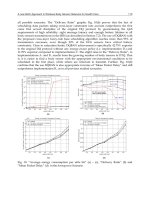
Fig. 3. Design and view of sensor
The final probe is enclosed in a sphere of 23 mm in diameter, which protects circuitry and
allows the density of the probe to be equal to the water density.
The circuit for measuring the temperature has been designed based on a miniature Pt100
element that is located on the surface of the sphere. The conditioning circuit is designed to
satisfy the size and consumption specifications. The Pt100 sensor is polarized by a current
source that is integrated in an ultra low power consumption circuit and an instrumentation
amplifier. This amplifier is also ultra low power, and the output signal is adjusted to the
desired measurement range. Both components have a shut down signal that only switched
on at the moment of measurement. The current consumption is 10uA in off mode and
1.58mA in on mode.
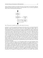
4. Firmware considerations
The microcontroller containing each autonomous probe is responsible for the smooth
running of the probe. It properly manages wireless communications, acquisition and storage
of data, and the states of work of the circuit. To achieve the requirements of energy saving,
the firmware developed for each of the autonomous probe has been structured in four
states:
Power down
Configuration
In acquisition
Down load
The “Power down” state is the key to achieving that the probes have a long life. It is the state
that stays in longer, and the state the probe enters at the end of each data collection cycle or
if it exceeds a certain amount of time without communication with the control system. To
escape the "Power down" state, a reset signal is applied to the microcontroller, which
becomes active and enters to "Configuration" mode. This mode begins a communication
with the coordinator node, where the probe is identified (ID) and receives the configuration
of the monitoring and the actual clock. After a timeout, the sensor initiates the acquisition
and the temporal buffering of temperatures, i.e., it switches to the "In acquisition" state. In
this state, the microcontroller is sleeping between two acquisitions and is characterized by
using the secondary oscillator, which only drives the peripheral that remains in operation:
the timer that sets the sampling period. The circuit that conditions the signal from the Pt100
is activated moments before the measurement, and immediately returns to the low power
state. At the conclusion of the scheduled number of acquisitions, the probe goes to the
"Down load" state, recovering the main oscillator and establishing communication with the
control system to transfer data. When the transfer is finished, it is passed to the "Power
down" state.
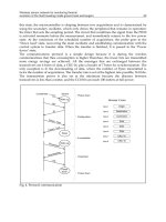
The communications protocol is a simple design because it is during the wireless
communications that thee consumption is higher Therefore, the fewer bits are transmitted
more energy savings are achieved. All the messages that are exchanged between the
transceivers are 6 bytes of data, a CRC-16, plus a header of 7 bytes for synchronization. The
only exception is in the downloading of data, where the number of bytes transmitted is
twice the number of acquisitions. The transfer rate is set at the highest rate possible, 76.8 kbs.
The transmission power is also set at the minimum because the distance between
transceivers is less than a meter, and the CC1010 can reach 100 meters at full power.
Fig. 4. Protocol communication
Emerging Communications for Wireless Sensor Networks34
5. Time synchronization considerations
Another key to the reliability of the obtained data is the time synchronization: all probes
must have the same clock as a reference for the estimated time of acquisition. Since the
evolution of temperature on the heat exchanger is slow, the accuracy in time between all the
probes must be better than 100ms. There are different synchronization techniques in
wireless sensor networks (Sundararaman 2005, Jones 2001), but to meet the energy
restrictions of the instrument, the so-called Synchronization Reference Broadcasts (Elson
2002) was used for its ease of implementation and the low power consumption added.
The coordinator node is responsible for sending the reference clock to the probe, which has
just been removed from the “Power Down” state, and requests its identification. Together
with the command to start the acquisition, the current value of the clock is sent, and the
probe will take this as its initial value of local clock. All subsequent acquisitions are
referenced to this clock, thereby completing the synchronization. Although there will be a
time delay between the clock sent by the coordinator and the sensor, due to the time of
transmission and processing of messages (since all probes have the same latency) the time
between two consecutive samples is well known. The confirmation of the correct
initialization of the local clock of each sensor is done via the sensor's response message to
the coordinator.
The frame of data downloaded from the sensor includes the clock that was posted at the
beginning of the acquisition, which allows the synchronization of data with on accuracy of
better than 100 ms. Spatial synchronization is simpler; it depends of the moment in which
the sensor is inserted into the flow of water, and this is controlled by the coordinator node,
which performs the insertion of a certain time after receiving confirmation of the message
startup acquisition. Since the flow rate and the section of the pipe are known, the point at
which each temperature measurement is being made can be estimated perfectly.
6. Other implementations
The hardware solution adopted was taken after valuing other existing alternatives in the
market that, still complying with the basic requirements, did not completely satisfy our
needs. When we speak of RF communications, we have to always keep in mind the range,
the charge, the need to use a standard, the price… In the current market, there are devices
that work under the GHz, devices that work above the GHz, and devices that use a standard
protocol (ZigBee, Wireless HART, Bluetooth ).
Our solution is from the first group due to the need to find an intermediate point among
frequency of work, reach, power at the outset, environment, and consumption. Besides, we
have an indispensable requirement, the size.
A success factor for the instrument is to obtain good quality communication while still
maintaining very low consumption; the factors of propagation, attenuation, and shielding
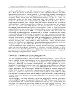
must be balanced to do this. Figure 5 shows the relationship between transmission quality
and carrier frequency; the best choice is to work in the sub-Gigahertz range.
Of the options under the GHz that use no standard protocol, the followings families of
devices can be found:
- ADF70XX of Analog Devices
- MC33XXX of Freescale
- TDAXXXX of Infineon
- CC11XX of Texas Instruments
- rfPIC12XXXX of Microchip
- MAXXXX of Maxim
Table 2 summarizes the main characteristics of these families.
Fig. 5. Quality Tx versus frequency
Device
Band
(MHz)
Modulation
Current
(mA)
Voltag
e (V)
Baudrate
(kbps)
Power
(dBm)
Package
ADF70XX 433-915 FSK/ASK 30 2-3,6 76/384 13 TSSOP
MC33XXX 304-915 OOK/FSK 25 2,1-5,5 20 7 LQFP
TDAXXXX 434-870 ASK/FSK 35 2,1-5,5 100 13 TSSOP
CC11XX 315-915 FSK/OOK 16 2-3,6 500 13 QFN
rfPIC12XXXX 310-480 ASK/FSK 20 2,7-5 80 6 SSOP
MAXXXX 300-450 ASK/FSK 5,3 3,3-5 70 10 QFN
Table 2. Main characteristics for devices < 1 GHz
As can be observed, the Analog Devices solution complies with the broadcast velocity
requirements, power, and package. However, it does not comply with the consumption nor
does it incorporate the transmitter and the microcontroller in the same device. The same
occurs with the families of Freescale, Infineon, and Maxim; although Maxim has the lowest
consumption.
The families of Texas Instruments and of Microchip meet the requirement of having a single
chip for both components, although the price was higher than that of the solution adopted.
Wireless sensor network for monitoring thermal
evolution of the uid traveling inside ground heat exchangers 35
5. Time synchronization considerations
Another key to the reliability of the obtained data is the time synchronization: all probes
must have the same clock as a reference for the estimated time of acquisition. Since the
evolution of temperature on the heat exchanger is slow, the accuracy in time between all the
probes must be better than 100ms. There are different synchronization techniques in
wireless sensor networks (Sundararaman 2005, Jones 2001), but to meet the energy
restrictions of the instrument, the so-called Synchronization Reference Broadcasts (Elson
2002) was used for its ease of implementation and the low power consumption added.
The coordinator node is responsible for sending the reference clock to the probe, which has
just been removed from the “Power Down” state, and requests its identification. Together
with the command to start the acquisition, the current value of the clock is sent, and the
probe will take this as its initial value of local clock. All subsequent acquisitions are
referenced to this clock, thereby completing the synchronization. Although there will be a
time delay between the clock sent by the coordinator and the sensor, due to the time of
transmission and processing of messages (since all probes have the same latency) the time
between two consecutive samples is well known. The confirmation of the correct
initialization of the local clock of each sensor is done via the sensor's response message to
the coordinator.
The frame of data downloaded from the sensor includes the clock that was posted at the
beginning of the acquisition, which allows the synchronization of data with on accuracy of
better than 100 ms. Spatial synchronization is simpler; it depends of the moment in which
the sensor is inserted into the flow of water, and this is controlled by the coordinator node,
which performs the insertion of a certain time after receiving confirmation of the message
startup acquisition. Since the flow rate and the section of the pipe are known, the point at
which each temperature measurement is being made can be estimated perfectly.
6. Other implementations
The hardware solution adopted was taken after valuing other existing alternatives in the
market that, still complying with the basic requirements, did not completely satisfy our
needs. When we speak of RF communications, we have to always keep in mind the range,
the charge, the need to use a standard, the price… In the current market, there are devices
that work under the GHz, devices that work above the GHz, and devices that use a standard
protocol (ZigBee, Wireless HART, Bluetooth ).
Our solution is from the first group due to the need to find an intermediate point among
frequency of work, reach, power at the outset, environment, and consumption. Besides, we
have an indispensable requirement, the size.
A success factor for the instrument is to obtain good quality communication while still
maintaining very low consumption; the factors of propagation, attenuation, and shielding
must be balanced to do this. Figure 5 shows the relationship between transmission quality
and carrier frequency; the best choice is to work in the sub-Gigahertz range.
Of the options under the GHz that use no standard protocol, the followings families of
devices can be found:
- ADF70XX of Analog Devices
- MC33XXX of Freescale
- TDAXXXX of Infineon
- CC11XX of Texas Instruments
- rfPIC12XXXX of Microchip
- MAXXXX of Maxim
Table 2 summarizes the main characteristics of these families.
Fig. 5. Quality Tx versus frequency
Device
Band
(MHz)
Modulation
Current
(mA)
Voltag
e (V)
Baudrate
(kbps)
Power
(dBm)
Package
ADF70XX 433-915 FSK/ASK 30 2-3,6 76/384 13 TSSOP
MC33XXX 304-915 OOK/FSK 25 2,1-5,5 20 7 LQFP
TDAXXXX 434-870 ASK/FSK 35 2,1-5,5 100 13 TSSOP
CC11XX 315-915 FSK/OOK 16 2-3,6 500 13 QFN
rfPIC12XXXX 310-480 ASK/FSK 20 2,7-5 80 6 SSOP
MAXXXX 300-450 ASK/FSK 5,3 3,3-5 70 10 QFN
Table 2. Main characteristics for devices < 1 GHz
As can be observed, the Analog Devices solution complies with the broadcast velocity
requirements, power, and package. However, it does not comply with the consumption nor
does it incorporate the transmitter and the microcontroller in the same device. The same
occurs with the families of Freescale, Infineon, and Maxim; although Maxim has the lowest
consumption.
The families of Texas Instruments and of Microchip meet the requirement of having a single
chip for both components, although the price was higher than that of the solution adopted.
Emerging Communications for Wireless Sensor Networks36
If we go to solutions above the GHz that do not require a standard, the following families
can be found:
- MC13XXX of Freescale
- CC25XX of Texas Instruments
- CYWMXXXX of Cypress
- CyFi of Cypress
- MRF24JXX of Microchip
Table 3 summarizes the main characteristics of these families.
Device
Band
(GHz)
Modulation
Current
(mA)
Voltag
e (V)
Baudrate
(kbps)
Power
(dBm)
Package
MC13XXX 2,4 GFSK/MSK 35 1,8-3,6 250 4 QFN
CC25XX 2,4 GFSK/MSK 23 2-3,6 500 10 QLP
CYWMXXXX 2,4 GFSK 20 2,7-3,6 64 17 QFN
CyFi 2,4 GFSK 12 1,8-3,6 1000 12 QFN
MRF24JXX 2,4 GFSK/MSK 22 2,3-3,6 250 3 QFN
Table 3. Main characteristics for devices > 1 GHz
The family of Freescale with these circuits for wireless communications, together with the
microcontrollers of very low consumption of 8 bits of the family S08, allow ready point and
point-to-multipoint communications to be implemented. This family is not of interest due to
the high consumption and the need to have two components.
Texas Instruments acquired Chipcon to complete its range of wireless products including
the Zigbee. Since the transceiver CC25XX has very few components, it does not need an
electric antenna switch or a filter, providing great benefits and low consumption. It also
offers programmable power sensibility at the outset. The CC25XX is a circuit of very low
consumption that includes the transmitter and a microcontroller based on the core 8051 at
32MHz.
Cypress began with RF solutions to 2,4GHz for PC and the USB markets. It has several
characteristics that distinguish it from other competitors such as very low consumption,
immunity to interferences, generation of CRC, an auto transactions sequencer, etc. The
advantages of this technology is that it has entered the consumer market (mice, keyboards,
joysticks, ) as well as the industrial market at a very low cost for ready point or point-to-
multipoint applications. This technology can also be used even though the price is a lot
higher than the solution adopted.
Cypress also presents a solution called CyFi to 2,4 GHz optimized for control since it has a
PSoC microcontroller and a DSSS transmitter with, with a protocol that is easy to use for a
network in star and with optimized consumption. The RF solution CyFi, of low
consumption, is extremely dependable and easy to use to 2,4 GHz within an extensive
range of applications. It allows designers to create high reliability systems in wireless
communication, reducing the complexity of development and ensuring low power
consumption. The CyFi networks vary the channel of work dynamically, the velocity of
broadcast and the real-time power at the outset in order to maintain dependable
communications in the presence of interferences. Besides having very low activity and a
sleep mode, the CyFi solution greatly improves low consumption. CyFi networks minimize
periods of peak consumption and maximize the periods of low power state. This solution
was not adopted due to the difficulty of integrating it into the size of our system when using
two components.
Microchip offers a solution based on its microcontrollers and a proprietary protocol called
Miwi™ (Microchip Wireless). It is directed to low cost devices and networks that do not
need high transfer of data, over short distances (100 meters without obstacles), and with
minimum energy consumption. As occurs with CyFi, the reduced space of our system forces
us to reject this solution. We can conclude that within the market of wireless technologies,
there is an extensive range of possibilities. Some of them may improve and change
continuously, and we must keep them in mind for a new generation of instrument.
7. Energy harvesting
European legislation imposes restrictions on the use of batteries in electronic devices
(European Parliament and Council, Directives 2006/66/EC and 2008/103/EC) and their
recycling. The instrument developed uses button batteries to supply the autonomous
probes; its final design must meet current legislation. While this directive covers exceptions
to the restrictions on the use of batteries, one way of reducing their presence, without
compromising the design, is to completely dispense with batteries or reduce the needs of
replacing them by increasing the lifetime of the sensors. The most convenient way to achieve
this is to use energy that can be collected in the environment, i.e., using techniques of
"energy harvesting". Energy harvesting has become an important emerging area of low
power technology (Cymbet 2009, Mateu 2007) that can provide energy for smaller-scale
needs such as sensor networks, utilizing the vibrations inherent in structures, vehicles, and
machinery or from wind and solar systems. These can drive sensors while eliminating the
need for wires and batteries.
The energy sources that are most commonly used in energy harvesting are mechanical
energy (vibration), light, electromagnetic, thermal and piezoelectric (Paradiso 2005). The
power that can be captured from these sources is summarized in Table 4.
Source Power Harvesting technologies
Light
100uW/cm2 to
100 mW/cm2
Photovoltaic
Vibrational
4 uW/cm3 to
800uW/cm3
Piezoelectric cantilever
Thermoelectric 60uW/cm2 Thermogenerator
Radio frequency ~1uW/cm2 Antenna
Push button 50uJ/N Electromagnetic, piezoelectric
Table 4. Capabilities of energy harvesting
In our instrument, we estimate that energy harvesting can be applied to power the sensors,
using light or heat as an energy source or heat. With light, we can embed small photovoltaic
cells in the cover of the sensor. With heat, we can incorporate small thermo generators based
on Seebeck effect in the cover of the sensor. A circuit for power conversion and energy
storage should be added. The device for storage can be a secondary battery or a capacitor
Wireless sensor network for monitoring thermal
evolution of the uid traveling inside ground heat exchangers 37
If we go to solutions above the GHz that do not require a standard, the following families
can be found:
- MC13XXX of Freescale
- CC25XX of Texas Instruments
- CYWMXXXX of Cypress
- CyFi of Cypress
- MRF24JXX of Microchip
Table 3 summarizes the main characteristics of these families.
Device
Band
(GHz)
Modulation
Current
(mA)
Voltag
e (V)
Baudrate
(kbps)
Power
(dBm)
Package
MC13XXX 2,4 GFSK/MSK 35 1,8-3,6 250 4 QFN
CC25XX 2,4 GFSK/MSK 23 2-3,6 500 10 QLP
CYWMXXXX 2,4 GFSK 20 2,7-3,6 64 17 QFN
CyFi 2,4 GFSK 12 1,8-3,6 1000 12 QFN
MRF24JXX 2,4 GFSK/MSK 22 2,3-3,6 250 3 QFN
Table 3. Main characteristics for devices > 1 GHz
The family of Freescale with these circuits for wireless communications, together with the
microcontrollers of very low consumption of 8 bits of the family S08, allow ready point and
point-to-multipoint communications to be implemented. This family is not of interest due to
the high consumption and the need to have two components.
Texas Instruments acquired Chipcon to complete its range of wireless products including
the Zigbee. Since the transceiver CC25XX has very few components, it does not need an
electric antenna switch or a filter, providing great benefits and low consumption. It also
offers programmable power sensibility at the outset. The CC25XX is a circuit of very low
consumption that includes the transmitter and a microcontroller based on the core 8051 at
32MHz.
Cypress began with RF solutions to 2,4GHz for PC and the USB markets. It has several
characteristics that distinguish it from other competitors such as very low consumption,
immunity to interferences, generation of CRC, an auto transactions sequencer, etc. The
advantages of this technology is that it has entered the consumer market (mice, keyboards,
joysticks, ) as well as the industrial market at a very low cost for ready point or point-to-
multipoint applications. This technology can also be used even though the price is a lot
higher than the solution adopted.
Cypress also presents a solution called CyFi to 2,4 GHz optimized for control since it has a
PSoC microcontroller and a DSSS transmitter with, with a protocol that is easy to use for a
network in star and with optimized consumption. The RF solution CyFi, of low
consumption, is extremely dependable and easy to use to 2,4 GHz within an extensive
range of applications. It allows designers to create high reliability systems in wireless
communication, reducing the complexity of development and ensuring low power
consumption. The CyFi networks vary the channel of work dynamically, the velocity of
broadcast and the real-time power at the outset in order to maintain dependable
communications in the presence of interferences. Besides having very low activity and a
sleep mode, the CyFi solution greatly improves low consumption. CyFi networks minimize
periods of peak consumption and maximize the periods of low power state. This solution
was not adopted due to the difficulty of integrating it into the size of our system when using
two components.
Microchip offers a solution based on its microcontrollers and a proprietary protocol called
Miwi™ (Microchip Wireless). It is directed to low cost devices and networks that do not
need high transfer of data, over short distances (100 meters without obstacles), and with
minimum energy consumption. As occurs with CyFi, the reduced space of our system forces
us to reject this solution. We can conclude that within the market of wireless technologies,
there is an extensive range of possibilities. Some of them may improve and change
continuously, and we must keep them in mind for a new generation of instrument.
7. Energy harvesting
European legislation imposes restrictions on the use of batteries in electronic devices
(European Parliament and Council, Directives 2006/66/EC and 2008/103/EC) and their
recycling. The instrument developed uses button batteries to supply the autonomous
probes; its final design must meet current legislation. While this directive covers exceptions
to the restrictions on the use of batteries, one way of reducing their presence, without
compromising the design, is to completely dispense with batteries or reduce the needs of
replacing them by increasing the lifetime of the sensors. The most convenient way to achieve
this is to use energy that can be collected in the environment, i.e., using techniques of
"energy harvesting". Energy harvesting has become an important emerging area of low
power technology (Cymbet 2009, Mateu 2007) that can provide energy for smaller-scale
needs such as sensor networks, utilizing the vibrations inherent in structures, vehicles, and
machinery or from wind and solar systems. These can drive sensors while eliminating the
need for wires and batteries.
The energy sources that are most commonly used in energy harvesting are mechanical
energy (vibration), light, electromagnetic, thermal and piezoelectric (Paradiso 2005). The
power that can be captured from these sources is summarized in Table 4.
Source Power Harvesting technologies
Light
100uW/cm2 to
100 mW/cm2
Photovoltaic
Vibrational
4 uW/cm3 to
800uW/cm3
Piezoelectric cantilever
Thermoelectric 60uW/cm2 Thermogenerator
Radio frequency ~1uW/cm2 Antenna
Push button 50uJ/N Electromagnetic, piezoelectric
Table 4. Capabilities of energy harvesting
In our instrument, we estimate that energy harvesting can be applied to power the sensors,
using light or heat as an energy source or heat. With light, we can embed small photovoltaic
cells in the cover of the sensor. With heat, we can incorporate small thermo generators based
on Seebeck effect in the cover of the sensor. A circuit for power conversion and energy
storage should be added. The device for storage can be a secondary battery or a capacitor
Emerging Communications for Wireless Sensor Networks38
(supercapacitor, Goldcap, etc.). The first method allows more energy density, but has
limited life due to charge-discharge cycles and presents a small discharge current. The
second method has an infinite life that is not affected by charge- discharge cycles, and
presents a discharge curve that is non constant and has a small density of energy.
8. Conclusions
Achieving GCHP designs that are more accurate and tailored to soil conditions requires new
tools and methods for calculating thermal soil properties. For the expansion of GCHP, it is
essential to develop simpler and more economic methods in time and cost for BHE sizing.
The instrument under development contributes to this goal by providing a device that offers
easy transportation and installation, small size, and the possibility of operation by non-
specialists.
We have verified that it is possible to insert and extract small probes, which contain a
miniaturized acquisition system, for temperature monitoring of the water flowing along the
pipes of the BHE. It is possible to configure each probe with the desired parameters for
monitoring temperature inside the pipes by wireless transmission. In autonomous mode,
each probe completes the acquisition and, once the probe is extracted, downloads
automatically the acquired data also by wireless transmission. The data collected and
recorded on a PC, allows the design of a new analysis that takes into account the dynamics
of the BHE. Some as yet untapped possibilities should be studied and quantified, such as
groundwater flows, the effects of convective wet layers, etc. Accurate assessment of soil
thermal recovery, and hence, the effects of saturation and thermal degradation of the
efficiency that can occur in a particular installation must also be studied and quantified.
9. Acknowledgments
This work has been supported by the Spanish Government under projects “Modelado y
simulación de sistemas energéticos complejos” (2005 Ramón y Cajal Program), “Modelado,
simulación y validación experimental de la transferencia de calor en el entorno de la
edificación” (ENE2008-0059/CON) and by the Valencian Government under project
“Diseño y desarrollo de un instrumento de medida para la caracterización de
intercambiadores de calor.” (GV/2007/058).
The instrument has been patent pending since November of 2008.
10. References
Austin, W. A. (1998). Development of an in-situ system for measuring ground thermal
properties. M.S. thesis, Oklahoma State University, Stillwater, OK, USA, 177 pp.
Beier, R.A. (2008). Equivalent Time for Interrupted Tests on Borehole Heat Exchangers.
International Journal of HVAC & R Research 14, 489-503.
Bose, J.E.; Smith, M.D.; Spitler, J.D. (2002). Advances in ground source heat pump systems.
An international overview. 7
th
IEA Conference on Heat Pump Technologies, Beijing
(China)
Carslaw, H.S.; Jaeger, J.C. (1959). Conduction of Heat in Solids, Oxford University Press, New
York, NY, USA, 510 pp.
Cymbet Corporation (2009). White paper: Zero power wireless sensor
Elson, J.; Girod, L.; Estrin, D. (2002). Fine-Grained network time synchronization using
reference broadcasts. Proceedings Fifth Symposium on Operating Systems Design and
Implementation (OSDI 2002) Vol. 36, 147-163.
Eskilson P. (1987). Thermal Analysis of Heat Extraction Boreholes. PhD. Thesis, Dept. of
Mathematical Physics, University of Lund, Lund, Sweden, 264 pp.
Eklöf, F.; Gehlin, S. (1996). A mobile equipment for Geothermal Response Test. M.S. thesis,
Lulea University of Technology, Lulea, Sweden, 65 pp.
European Parliament and Council, Directive 2008/103/EC, Batteries and accumulators and
waste batteries and accumulators as regards placing batteries and accumulators on the
market
European Parliament and Council, Directive 2006/66/EC, Batteries and accumulators and
waste batteries and accumulators and repealing Directive
Genchi, Y.; Kikegawa, Y.; Inaba, A. (2002) CO2 payback-time assessment of a regional-scale
heating and cooling system using a ground source heat-pump in a high energy-
consumption area in Tokyo. Applied Energy Vol.71, 147-160
Hellström, G. (1991). Thermal Analysis of Duct Storage System. Dep. of Mathematical Physics,
University of Lund, Lund, Sweden, 262 pp.
Hurtig, E.; Ache, B.; Großwig, S.; Hänsel, K. (2000). Fiber optic temperature measurements: a
new approach to determine the dynamic behavior of the heat exchanging medium
inside a borehole heat exchange. TERRASTOCK 2000, 8th International Conference on
Thermal Energy Storage Stuttgart. August 28th to September 1st, 2000.
Jones, C.E.; Sivalingam, K.M.; Agrawal, P.; Chen, J. (2001). A survey of energy efficient
network protocols for wireless networks. Wireless networks 7, 343-358
Lund, J.W. (2000). Ground source (geothermal) heat pumps. In: Course on heating with
geothermal energy: conventional and new schemes. Lineau P.J. (editor). World
Geothermal Congress 2000 Short Courses. Kazuno, Japan, pp. 209-236.
Martos, J.; Torres, J.; Soret, J.; Montero, A. (2008). Wireless sensor network for measuring
thermal properties of borehole heat exchangers. Proceedings IEEE International
Conference on Sustainable Energy Technologies (ICSET 2008), Singapur
Mateu, L.; Codrea, C.; Lucas, N.; Pollack, M.; Spies, P. (2007). Human body energy
harvesting thermogenerator for sensing applications. International Conference on
Sensor Technologies and Applications SENSORCOMM 2007,Valencia, Spain
Mogensen, P. (1983). Fluid to duct wall heat transfer in duct system heat storage. Proceedings
of the International Conference on Surface Heat Storage in Theory and Practice, Sweden,
Stockholm, pp. 652-657.
Nordell, B.; Reuss, M.; G. Hellström, G. (2006). Annex 21: Thermal Response Test. Draft.
Omer, A M. (2008). Ground-source heat pump systems and applications. Renewable and
Sustainable Energy Reviews 12, 344-371.
Paradiso, J.A.; Starner, T. (2005). Energy scavenging for mobile and wireless electronics.
IEEE Pervasive Computing Vol 4, Issue 1, 18-27
Rohner, E.; Rybach, L.; Schaärli, U. (2005). A new, small, wireless instrument to determine
ground thermal conductivity In-Situ for borehole heat exchange design.
Proceedings
World Geothermal Congress 2005, Antalya, Turkey.
Sanner, B.; Karytsas, C.; Mendrinos, D.; Rybach, L. (2003). Current status of ground source heat
pumps and underground thermal storage in Europe. Geothermics 32, 579-588.
Wireless sensor network for monitoring thermal
evolution of the uid traveling inside ground heat exchangers 39
(supercapacitor, Goldcap, etc.). The first method allows more energy density, but has
limited life due to charge-discharge cycles and presents a small discharge current. The
second method has an infinite life that is not affected by charge- discharge cycles, and
presents a discharge curve that is non constant and has a small density of energy.
8. Conclusions
Achieving GCHP designs that are more accurate and tailored to soil conditions requires new
tools and methods for calculating thermal soil properties. For the expansion of GCHP, it is
essential to develop simpler and more economic methods in time and cost for BHE sizing.
The instrument under development contributes to this goal by providing a device that offers
easy transportation and installation, small size, and the possibility of operation by non-
specialists.
We have verified that it is possible to insert and extract small probes, which contain a
miniaturized acquisition system, for temperature monitoring of the water flowing along the
pipes of the BHE. It is possible to configure each probe with the desired parameters for
monitoring temperature inside the pipes by wireless transmission. In autonomous mode,
each probe completes the acquisition and, once the probe is extracted, downloads
automatically the acquired data also by wireless transmission. The data collected and
recorded on a PC, allows the design of a new analysis that takes into account the dynamics
of the BHE. Some as yet untapped possibilities should be studied and quantified, such as
groundwater flows, the effects of convective wet layers, etc. Accurate assessment of soil
thermal recovery, and hence, the effects of saturation and thermal degradation of the
efficiency that can occur in a particular installation must also be studied and quantified.
9. Acknowledgments
This work has been supported by the Spanish Government under projects “Modelado y
simulación de sistemas energéticos complejos” (2005 Ramón y Cajal Program), “Modelado,
simulación y validación experimental de la transferencia de calor en el entorno de la
edificación” (ENE2008-0059/CON) and by the Valencian Government under project
“Diseño y desarrollo de un instrumento de medida para la caracterización de
intercambiadores de calor.” (GV/2007/058).
The instrument has been patent pending since November of 2008.
10. References
Austin, W. A. (1998). Development of an in-situ system for measuring ground thermal
properties. M.S. thesis, Oklahoma State University, Stillwater, OK, USA, 177 pp.
Beier, R.A. (2008). Equivalent Time for Interrupted Tests on Borehole Heat Exchangers.
International Journal of HVAC & R Research 14, 489-503.
Bose, J.E.; Smith, M.D.; Spitler, J.D. (2002). Advances in ground source heat pump systems.
An international overview. 7
th
IEA Conference on Heat Pump Technologies, Beijing
(China)
Carslaw, H.S.; Jaeger, J.C. (1959). Conduction of Heat in Solids, Oxford University Press, New
York, NY, USA, 510 pp.
Cymbet Corporation (2009). White paper: Zero power wireless sensor
Elson, J.; Girod, L.; Estrin, D. (2002). Fine-Grained network time synchronization using
reference broadcasts. Proceedings Fifth Symposium on Operating Systems Design and
Implementation (OSDI 2002) Vol. 36, 147-163.
Eskilson P. (1987). Thermal Analysis of Heat Extraction Boreholes. PhD. Thesis, Dept. of
Mathematical Physics, University of Lund, Lund, Sweden, 264 pp.
Eklöf, F.; Gehlin, S. (1996). A mobile equipment for Geothermal Response Test. M.S. thesis,
Lulea University of Technology, Lulea, Sweden, 65 pp.
European Parliament and Council, Directive 2008/103/EC, Batteries and accumulators and
waste batteries and accumulators as regards placing batteries and accumulators on the
market
European Parliament and Council, Directive 2006/66/EC, Batteries and accumulators and
waste batteries and accumulators and repealing Directive
Genchi, Y.; Kikegawa, Y.; Inaba, A. (2002) CO2 payback-time assessment of a regional-scale
heating and cooling system using a ground source heat-pump in a high energy-
consumption area in Tokyo. Applied Energy Vol.71, 147-160
Hellström, G. (1991). Thermal Analysis of Duct Storage System. Dep. of Mathematical Physics,
University of Lund, Lund, Sweden, 262 pp.
Hurtig, E.; Ache, B.; Großwig, S.; Hänsel, K. (2000). Fiber optic temperature measurements: a
new approach to determine the dynamic behavior of the heat exchanging medium
inside a borehole heat exchange. TERRASTOCK 2000, 8th International Conference on
Thermal Energy Storage Stuttgart. August 28th to September 1st, 2000.
Jones, C.E.; Sivalingam, K.M.; Agrawal, P.; Chen, J. (2001). A survey of energy efficient
network protocols for wireless networks. Wireless networks 7, 343-358
Lund, J.W. (2000). Ground source (geothermal) heat pumps. In: Course on heating with
geothermal energy: conventional and new schemes. Lineau P.J. (editor). World
Geothermal Congress 2000 Short Courses. Kazuno, Japan, pp. 209-236.
Martos, J.; Torres, J.; Soret, J.; Montero, A. (2008). Wireless sensor network for measuring
thermal properties of borehole heat exchangers. Proceedings IEEE International
Conference on Sustainable Energy Technologies (ICSET 2008), Singapur
Mateu, L.; Codrea, C.; Lucas, N.; Pollack, M.; Spies, P. (2007). Human body energy
harvesting thermogenerator for sensing applications. International Conference on
Sensor Technologies and Applications SENSORCOMM 2007,Valencia, Spain
Mogensen, P. (1983). Fluid to duct wall heat transfer in duct system heat storage. Proceedings
of the International Conference on Surface Heat Storage in Theory and Practice, Sweden,
Stockholm, pp. 652-657.
Nordell, B.; Reuss, M.; G. Hellström, G. (2006). Annex 21: Thermal Response Test. Draft.
Omer, A M. (2008). Ground-source heat pump systems and applications. Renewable and
Sustainable Energy Reviews 12, 344-371.
Paradiso, J.A.; Starner, T. (2005). Energy scavenging for mobile and wireless electronics.
IEEE Pervasive Computing Vol 4, Issue 1, 18-27
Rohner, E.; Rybach, L.; Schaärli, U. (2005). A new, small, wireless instrument to determine
ground thermal conductivity In-Situ for borehole heat exchange design.
Proceedings
World Geothermal Congress 2005, Antalya, Turkey.
Sanner, B.; Karytsas, C.; Mendrinos, D.; Rybach, L. (2003). Current status of ground source heat
pumps and underground thermal storage in Europe. Geothermics 32, 579-588.
Emerging Communications for Wireless Sensor Networks40
Spitler, J.D. (2005). Ground-Source heat Pump System Research - Past, Present and Future.
International Journal of HVAC & R Research 11, 165-167.
Sundararaman, B.; Buy, U.; Kshemkalyani, A.D. (2005). Clock synchronization for wireless sensor
networks: a survey, Ad-Hoc network, 3(3): 282-323
Urchueguía, J.F.; Zacarés, M.; Corberán, J.M.; Montero, Á.; Martos, J.; Witte, H. (2008).
Comparison between the energy performance of a ground-coupled water to water
heat pump system and an air to water heat pump system for heating and cooling in
typical conditions of the European Mediterranean Coast. Energy Conversion and
Management 49, 2917-2923.
U.S. EPA, (2008). Energy Star Program, US Environmental Protection Agency.
.
Witte, H.J.L.; van Gelder, G.J.; Spitler, J.D. (2002). In Situ measurement of ground thermal
conductivity: a Dutch perspective. ASHRAE Transactions 108, 1-10.
Automated Testing and Development of WSN Applications 41
Automated Testing and Development of WSN Applications
Mohammad Al Saad, Jochen Schiller and Elfriede Fehr
x
Automated Testing and
Development of WSN Applications
Mohammad Al Saad, Jochen Schiller and Elfriede Fehr
Freie Universität Berlin
Germany
1. Introduction
Over the course of time the application range of Wireless Sensor Networks will become
more varied and complex. A WSN may consist of several hundred sensor nodes, which are
independent processing units equipped with various sensors and which communicate
wirelessly. WSNs can be compared to wireless ad-hoc networks, but the sensor nodes are
constrained by very limited resources and suit the purpose of collecting and processing
sensory data.
Therefore it is increasingly important to programme it with the corresponding efficiency.
Programming can become more productive and robust, if it is subject to a systematic and
structured software development process, which enhances application and accommodates
for the sensor network’s operating conditions. The pivotal approach for this can be found in
the automated Software development process, during which administrational
functionalities, which are suitable for the operation of the Sensor Network, are integrated.
This constitutes the approach of our proposed Tool-Chain ScatterClipse (Al Saad et al.,
2008b). The architecture centric method of the model driven paradigm (Stahl et al., 2006) is
used for the automation. New in this case is that the models are not only used for
documentation or visualisation: The semantic and expressive formal models also act as a
method to completely and concisely represent important concepts as well as the domain’s
(platform’s) basic conditions. Such specific, yet technology neutral models, are inputted into
the configurable code generator and after their validation the corresponding software
artefact is generated and distributed to the appropriate platform (wireless sensors nodes).
The high degree of automation accelerates the development and testing of applications,
which are already running on sensor nodes. Furthermore substitutability and reusability of
the software artefacts are increased, because the artefacts, alongside the automated code
generation, are represented by their respective models. Both increase the development
process’s productivity. The model driven code generation is used to furthermore generate a
largely tailor made code, so that only the required amount of code is generated for the
sensor node’s intended roll. Thus the scarce memory space is not only optimised, but also
unnecessary calculating and energy intensive software modules are avoided. The decreased
portion of manually written code also reduces the possibility of a programmer’s careless
mistakes. In this process the validation on the model level plays an important role, because
4
Emerging Communications for Wireless Sensor Networks42
the earlier a mistake (bug) is discovered in the development process the more robust and
reliant it will become.
For automation purposes an appropriate generative infrastructure was developed
ScatterFactory (Al Saad et al., 2007a) and ScatterUnit (Al Saad et al., 2008a), which
constitutes the backbone of our platform or Tool-Chain. For the modelling a graphical
editor, based on the Eclipse Modelling Framework and the Graphical Modelling Framework
(GMF), was developed. For the examination of the basic conditions, which are linked to the
respective models, a real time validation was integrated into the editor, which also makes
the development process more robust. OpenArchitectureWare (oAW) framework is used as
the code generator, where the corresponding code is automatically generated from the
inputted model and this code is then deployed onto the deployed sensor nodes. All
frameworks are Eclipse platform open source projects.
Furthermore the emphasis lies on the integration of essential functionalities, which regard
the administration and Management of the Wireless Sensor Network, with the model driven
software development process. These shall not be isolated, but shall be seamlessly combined
with attributes like configuration, bug fixing, monitoring, user interaction, over the air
software updates as well as sensor status visualization (Al Saad et al., 2007b). This
combination potential is an important character of the platform. The realisation of such
combinations was achieved by the plug-in oriented architecture in accordance with the
Eclipse platform. On the one hand the user can operate certain plug-ins (functionalities)
independent from each other, so that a “separation of concerns” is achieved, and on the
other hand the user can navigate the different plug-ins collaboratively at the same time,
whereby coherence is achieved. In order to improve the platforms productivity, its main
features can be accessed in local as well as in remote, or internet based, mode. For this
reason one can, for example, operate the administration and configuration from a computer
in one location (for instance in a development or test laboratory) while the sensors are
deployed in real world conditions (for example an experiment field) in a different remote
location. This was realized by an ordinary client/server architecture.
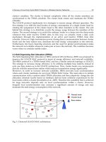
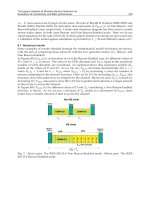
1.1 ScatterWeb WSN-Platform
ScatterWeb (Schiller et al., 2005) is a platform for teaching and prototyping WSN, which was
developed by our Work Group Computer Systems and Telematics of the Free University
Berlin. The hardware components of the ScatterWeb platform mainly consist of Embedded
sensor boards (ESBs), the newly developed configurable Modular sensor boards (MSBs) and
and the sink (eGate), which is connected to the PC via USB (see Figure 1). The sensor boards
have in addition to a controller and transceiver many functions at its disposal, such as a
sensor for luminosity, vibration, temperature and IR movement detection, a beeper, LEDS
(red, yellow and green), as well as a microphone. Thus a prototype of a comprehensive
monitoring sensor is created, which makes studying the insertion of WSNs in various areas
and scenarios – like environmental monitoring, intelligent buildings, Ad hoc process
control, etc. – possible. With this ability, various applications running on the computer can
communicate with ScatterWeb sensor boards via the eGate, and vice versa, which makes
data-gathering, debugging, monitoring, over the air software updates, etc. possible.
Fig. 1. ScatterWeb WSN-Platform: MSB left, ESB top right, eGate down right
1.2. Architecture Centric Model Driven Software Development (AC-MDSD)
While the main objectives of the OMG relative to the Model Driven Architecture (MDA) are
the increase of the portability and interoperational ability of the software on a universal
basis, the architecture centric model driven software development (AC-MDSD), as the name
states, puts the focus on each an application domain. Instead of generating the same
software for different platforms, the AC-MDSD has the goal of variations of software
(software families) for a certain domain to automate as much as possible. This attempt is
motivated with the observation that the (self repeating) infrastructure code has a
considerable part of the entire code-basis in similar applications. With eBusiness
applications, it lies around 70%, but with programming closer to the hardware, for instance
with embedded systems, this share lies often between 90 and 100% (Eisenecker &
Czarnecki., 2000). Consequently it is naturally preferred to create the part automatically so
that the actual application specific logic can be concentrated on. In this way, the
concentration is set on an application domain for a model language, which would allow the
concepts for the underlying platform to be domain related and precisely expressed.
Such a domain specific language (DSL) has as advantage over the usually more complex
UML-based models used in the MDA, that the models created in it have a more complete
knowledge of the domain. Since the model elements of DSL stand for concrete architectural
concepts or aspects of the domain, a model written in DSL offers a higher abstraction level,
but is concrete at the same time. The semantic gap between model and code becomes
smaller. As a side-effect this simplifies the transformation of the models to code, because the
step-by-step refinement of the models to code can often be skipped, since the underlying
platform is known and clearly restricted. Overall, the objective target of the paradigm of the
AC-MDSD can be compared to the use of modern product lines in the automobile industry.
At the beginning stands the prototype (Reference Implementation), in which the most
important concepts are included. The prototype shows what the vehicle that is to be
produced is supposed to look like. The construction plans (Models) serve as the starting
basis for the end product (Generated Artifact) and point out which units (Components) are
required.
In order to simplify the construction of the product line (Generative Architecture), as well as
the later production (Code-Generation), logical coherent Components are summarized to
production units. Production units, which are not automated or are too complicated to
Automated Testing and Development of WSN Applications 43
the earlier a mistake (bug) is discovered in the development process the more robust and
reliant it will become.
For automation purposes an appropriate generative infrastructure was developed
ScatterFactory (Al Saad et al., 2007a) and ScatterUnit (Al Saad et al., 2008a), which
constitutes the backbone of our platform or Tool-Chain. For the modelling a graphical
editor, based on the Eclipse Modelling Framework and the Graphical Modelling Framework
(GMF), was developed. For the examination of the basic conditions, which are linked to the
respective models, a real time validation was integrated into the editor, which also makes
the development process more robust. OpenArchitectureWare (oAW) framework is used as
the code generator, where the corresponding code is automatically generated from the
inputted model and this code is then deployed onto the deployed sensor nodes. All
frameworks are Eclipse platform open source projects.
Furthermore the emphasis lies on the integration of essential functionalities, which regard
the administration and Management of the Wireless Sensor Network, with the model driven
software development process. These shall not be isolated, but shall be seamlessly combined
with attributes like configuration, bug fixing, monitoring, user interaction, over the air
software updates as well as sensor status visualization (Al Saad et al., 2007b). This
combination potential is an important character of the platform. The realisation of such
combinations was achieved by the plug-in oriented architecture in accordance with the
Eclipse platform. On the one hand the user can operate certain plug-ins (functionalities)
independent from each other, so that a “separation of concerns” is achieved, and on the
other hand the user can navigate the different plug-ins collaboratively at the same time,
whereby coherence is achieved. In order to improve the platforms productivity, its main
features can be accessed in local as well as in remote, or internet based, mode. For this
reason one can, for example, operate the administration and configuration from a computer
in one location (for instance in a development or test laboratory) while the sensors are
deployed in real world conditions (for example an experiment field) in a different remote
location. This was realized by an ordinary client/server architecture.
1.1 ScatterWeb WSN-Platform
ScatterWeb (Schiller et al., 2005) is a platform for teaching and prototyping WSN, which was
developed by our Work Group Computer Systems and Telematics of the Free University
Berlin. The hardware components of the ScatterWeb platform mainly consist of Embedded
sensor boards (ESBs), the newly developed configurable Modular sensor boards (MSBs) and
and the sink (eGate), which is connected to the PC via USB (see Figure 1). The sensor boards
have in addition to a controller and transceiver many functions at its disposal, such as a
sensor for luminosity, vibration, temperature and IR movement detection, a beeper, LEDS
(red, yellow and green), as well as a microphone. Thus a prototype of a comprehensive
monitoring sensor is created, which makes studying the insertion of WSNs in various areas
and scenarios – like environmental monitoring, intelligent buildings, Ad hoc process
control, etc. – possible. With this ability, various applications running on the computer can
communicate with ScatterWeb sensor boards via the eGate, and vice versa, which makes
data-gathering, debugging, monitoring, over the air software updates, etc. possible.
Fig. 1. ScatterWeb WSN-Platform: MSB left, ESB top right, eGate down right
1.2. Architecture Centric Model Driven Software Development (AC-MDSD)
While the main objectives of the OMG relative to the Model Driven Architecture (MDA) are
the increase of the portability and interoperational ability of the software on a universal
basis, the architecture centric model driven software development (AC-MDSD), as the name
states, puts the focus on each an application domain. Instead of generating the same
software for different platforms, the AC-MDSD has the goal of variations of software
(software families) for a certain domain to automate as much as possible. This attempt is
motivated with the observation that the (self repeating) infrastructure code has a
considerable part of the entire code-basis in similar applications. With eBusiness
applications, it lies around 70%, but with programming closer to the hardware, for instance
with embedded systems, this share lies often between 90 and 100% (Eisenecker &
Czarnecki., 2000). Consequently it is naturally preferred to create the part automatically so
that the actual application specific logic can be concentrated on. In this way, the
concentration is set on an application domain for a model language, which would allow the
concepts for the underlying platform to be domain related and precisely expressed.
Such a domain specific language (DSL) has as advantage over the usually more complex
UML-based models used in the MDA, that the models created in it have a more complete
knowledge of the domain. Since the model elements of DSL stand for concrete architectural
concepts or aspects of the domain, a model written in DSL offers a higher abstraction level,
but is concrete at the same time. The semantic gap between model and code becomes
smaller. As a side-effect this simplifies the transformation of the models to code, because the
step-by-step refinement of the models to code can often be skipped, since the underlying
platform is known and clearly restricted. Overall, the objective target of the paradigm of the
AC-MDSD can be compared to the use of modern product lines in the automobile industry.
At the beginning stands the prototype (Reference Implementation), in which the most
important concepts are included. The prototype shows what the vehicle that is to be
produced is supposed to look like. The construction plans (Models) serve as the starting
basis for the end product (Generated Artifact) and point out which units (Components) are
required.
In order to simplify the construction of the product line (Generative Architecture), as well as
the later production (Code-Generation), logical coherent Components are summarized to
production units. Production units, which are not automated or are too complicated to
Emerging Communications for Wireless Sensor Networks44
automate, have to be done by hand (Manual Code). To offer a wide production palette
(System Family), the components, as a rule, have to be varied during the production
process, while the production platform as such is left unchanged. Thus in context of the AC-
MDSD, this approach is also called Product Line Engineering (see Figure 2).
Fig. 2. AC-MDSD as product-line
2. Testing Track
In our research, we examined how tools can support the person who writes test cases. With
this in mind, we particularly looked at automated testing of applications for wireless sensor
networks (WSNs). A WSN may consist of several hundred sensor nodes, which are
independent processing units equipped with various sensors and which communicate
wirelessly. WSNs can be compared to wireless ad hoc networks, but the sensor nodes are
constrained by very limited resources and suit the purpose of collecting and processing
sensory data. To test WSN applications, many common services are needed, e.g. the
simulation of sensor input. To provide those services, we implemented a testing framework
for our WSN platform ScatterWeb, called ScatterUnit.
2.1 ScatterUnit
Our aim was to create a general-purpose testing frame-work that enables automated tests of
WSN applications in respect to component, integration, and system tests. At first, we looked
at the spectrum of WSN applications that will potentially be tested using our framework in
order to elicit the requirements. A typical WSN application is to collect sensory data over a
period of time, which is then evaluated on a PC connected to the WSN, e.g. to keep an eye
on water pollution in a river (Akyildiz et al., 2002). A test scenario we may want to apply
works as follows:
1. Five sensor nodes to form the WSN.
2. All sensor nodes collect sensory data.
3. The collected data is read out by a PC connected to the WSN.
To write an automated test case for this test scenario, we need a testing framework which is
able to simulate sensor input, to invoke the functionality of the WSN application to read out
the collected data, and to observe if the correct data is transmitted to the PC. Thus, the
testing framework has to orchestrate the WSN application with mechanisms that in general
enable the test case to control the actions and observe the behaviour of the application.
When orchestrating the application with these mechanisms, we have to mind the intrusion
effect (Cunha et al., 2001): Because the mechanisms allocate resources on the sensor nodes
(e.g. processing time) they inevitably influence the execution of the application. This
intrusion may cause the application to fail, which it would not have without the
orchestration. This may be the case for applications which must react quickly and are
orchestrated with mechanisms that allocate significant processing time. Thus, the
mechanisms must not allocate resources that influence the execution of the application
unfavourably. The mechanisms needed to test the WSN application we mentioned above
allocate mainly processing time. This does not lead to an unfavourable intrusion since the
application is not constrained by timeliness. Because our aim was to create a general-
purpose testing framework, we do not consider WSN applications with stringent timeliness
constraints.
However, we found an unfavourable influence the orchestration can have on the execution
of the WSN application being tested when we looked at another typical test object: We may
also want to test a service used by many WSN applications, such as a routing protocol. A
simple test scenario is to establish a small multi-hop network and to send a data packet from
one sensor node to another, whereas the routing protocol has to forward the data packet on
one or more intermediate nodes. A test case for this scenario sends a data packet by using
the functionality of the routing protocol, observes through which intermediate nodes the
data packet is forwarded, and asserts that the data packet is received by the destination
node. When we execute this test case, the routing protocol may fail to deliver the data
packet because it was forwarded on a wrong route. To understand at which point the
routing protocol actually failed, we have to reconstruct the route the data packet took. For
that, we need the information of the observed forwarding actions on the intermediate nodes
in the correct order. Because this information is retrieved on different sensor nodes we have
to gather it at a central place for evaluation. A testing infrastructure that is able to do so is
SeNeTs (Blumenthal et al., 2004): A base station sends commands to the nodes in the
network – e.g. to initiate sending the data packet – and the nodes send information on all
relevant events back to the base station, i.e. where the route the data packet took is
reconstructed. However, this architecture was designed for wireless ad-hoc networks where
resources are not as limited as in WSNs. For WSNs we noticed that the transfer of a data
packet may fail if the radio channel was currently occupied by another sensor node (the
reason may be the occurrence of too many collisions on the radio channel). Therefore, we
cannot afford to establish a resource demanding communication between a base station and
the sensor nodes as SeNeTs does. To avoid an unfavourable influence on the execution of
the WSN application being tested, our testing frame-work must not use the radio channel
too frequently. Thus, we decided not to use a centralized but a decentralized approach
(Rafiq & Cacciar, 2003) for our testing framework ScatterUnit which meets the requirement
to produce the least possible intrusion effect.
To avoid sending commands over the radio channel each sensor node is configured with its
own set of actions before the execution of a test case is started. Those actions may call a
method of the application being tested, e.g. to send a data packet using the routing protocol.
They may also simulate an event, e.g. to simulate sensory data input. And they may be used
Automated Testing and Development of WSN Applications 45
automate, have to be done by hand (Manual Code). To offer a wide production palette
(System Family), the components, as a rule, have to be varied during the production
process, while the production platform as such is left unchanged. Thus in context of the AC-
MDSD, this approach is also called Product Line Engineering (see Figure 2).
Fig. 2. AC-MDSD as product-line
2. Testing Track
In our research, we examined how tools can support the person who writes test cases. With
this in mind, we particularly looked at automated testing of applications for wireless sensor
networks (WSNs). A WSN may consist of several hundred sensor nodes, which are
independent processing units equipped with various sensors and which communicate
wirelessly. WSNs can be compared to wireless ad hoc networks, but the sensor nodes are
constrained by very limited resources and suit the purpose of collecting and processing
sensory data. To test WSN applications, many common services are needed, e.g. the
simulation of sensor input. To provide those services, we implemented a testing framework
for our WSN platform ScatterWeb, called ScatterUnit.
2.1 ScatterUnit
Our aim was to create a general-purpose testing frame-work that enables automated tests of
WSN applications in respect to component, integration, and system tests. At first, we looked
at the spectrum of WSN applications that will potentially be tested using our framework in
order to elicit the requirements. A typical WSN application is to collect sensory data over a
period of time, which is then evaluated on a PC connected to the WSN, e.g. to keep an eye
on water pollution in a river (Akyildiz et al., 2002). A test scenario we may want to apply
works as follows:
1. Five sensor nodes to form the WSN.
2. All sensor nodes collect sensory data.
3. The collected data is read out by a PC connected to the WSN.
To write an automated test case for this test scenario, we need a testing framework which is
able to simulate sensor input, to invoke the functionality of the WSN application to read out
the collected data, and to observe if the correct data is transmitted to the PC. Thus, the
testing framework has to orchestrate the WSN application with mechanisms that in general
enable the test case to control the actions and observe the behaviour of the application.
When orchestrating the application with these mechanisms, we have to mind the intrusion
effect (Cunha et al., 2001): Because the mechanisms allocate resources on the sensor nodes
(e.g. processing time) they inevitably influence the execution of the application. This
intrusion may cause the application to fail, which it would not have without the
orchestration. This may be the case for applications which must react quickly and are
orchestrated with mechanisms that allocate significant processing time. Thus, the
mechanisms must not allocate resources that influence the execution of the application
unfavourably. The mechanisms needed to test the WSN application we mentioned above
allocate mainly processing time. This does not lead to an unfavourable intrusion since the
application is not constrained by timeliness. Because our aim was to create a general-
purpose testing framework, we do not consider WSN applications with stringent timeliness
constraints.
However, we found an unfavourable influence the orchestration can have on the execution
of the WSN application being tested when we looked at another typical test object: We may
also want to test a service used by many WSN applications, such as a routing protocol. A
simple test scenario is to establish a small multi-hop network and to send a data packet from
one sensor node to another, whereas the routing protocol has to forward the data packet on
one or more intermediate nodes. A test case for this scenario sends a data packet by using
the functionality of the routing protocol, observes through which intermediate nodes the
data packet is forwarded, and asserts that the data packet is received by the destination
node. When we execute this test case, the routing protocol may fail to deliver the data
packet because it was forwarded on a wrong route. To understand at which point the
routing protocol actually failed, we have to reconstruct the route the data packet took. For
that, we need the information of the observed forwarding actions on the intermediate nodes
in the correct order. Because this information is retrieved on different sensor nodes we have
to gather it at a central place for evaluation. A testing infrastructure that is able to do so is
SeNeTs (Blumenthal et al., 2004): A base station sends commands to the nodes in the
network – e.g. to initiate sending the data packet – and the nodes send information on all
relevant events back to the base station, i.e. where the route the data packet took is
reconstructed. However, this architecture was designed for wireless ad-hoc networks where
resources are not as limited as in WSNs. For WSNs we noticed that the transfer of a data
packet may fail if the radio channel was currently occupied by another sensor node (the
reason may be the occurrence of too many collisions on the radio channel). Therefore, we
cannot afford to establish a resource demanding communication between a base station and
the sensor nodes as SeNeTs does. To avoid an unfavourable influence on the execution of
the WSN application being tested, our testing frame-work must not use the radio channel
too frequently. Thus, we decided not to use a centralized but a decentralized approach
(Rafiq & Cacciar, 2003) for our testing framework ScatterUnit which meets the requirement
to produce the least possible intrusion effect.
To avoid sending commands over the radio channel each sensor node is configured with its
own set of actions before the execution of a test case is started. Those actions may call a
method of the application being tested, e.g. to send a data packet using the routing protocol.
They may also simulate an event, e.g. to simulate sensory data input. And they may be used
Emerging Communications for Wireless Sensor Networks46
to start waiting for a specific event, e.g. to wait for the reception of a data packet on the
radio channel. All actions which will be executed on the same sensor node are implemented
by a node script which also knows when to execute them. Thus, a node script has the
responsibility to control the execution of the test case locally on its sensor node. To
coordinate the actions executed on different sensor nodes, a command service is provided
by ScatterUnit (Ulrich et al., 1999). Sending commands for coordination is the only reason to
use the radio channel for testing purposes while the test case is running. During the
execution of the test case, all relevant events are logged on the sensor node where they
occur. Not until the execution of the test case was terminated the radio channel is used to
send the logs of all sensor nodes to a PC connected to the WSN. The PC uses these logs to
evaluate the behaviour of the application being tested and to decide whether a failure
occurred or not.
How to implement a test case using ScatterUnit is well demonstrated by a test case to test a
routing protocol. Especially in the field of WSNs, routing protocols must have the ability to
adapt to changing network topologies. To test this feature we apply the following test
scenario:
1. A WSN is set up with the topology shown in Figure 3 (left). (ScatterUnit provides a
topology simulation service which filters out received data packets from nodes virtually out
of range.)
2. Sensor node 1 sends a data packet to sensor node 4.
3. Sensor node 4 receives the data packet.
4. The WSN changes its topology in a way that the path between sensor node 1 and 4
changes: Sensor node 4 moves out of range of sensor node 3 and into range of sensor node 2
(see Figure 3 right).
5. Sensor node 1 sends a second data packet to sensor node 4.
6. Sensor node 4 receives the data packet.
Due to the changing topology of the WSN, the routing protocol has to choose a different
path to redirect the second data packet. If sensor node 4 does not receive the second packet
we would have shown that the routing protocol failed to adapt to the changed network
topology.
This test case is implemented by four node scripts – one for each sensor node. ScatterUnit
calls a set-up method of those node scripts before the execution of the test case is started.
This gives us the chance to initialize the topology simulation service provided by
ScatterUnit as depicted in Figure 3.
Fig. 3. WSN with four sensor nodes (left: nodes are within communication range of each
other, right: simulative modification of the topology while running the test)
This is all we have to implement for the node scripts of sensor nodes 2 and 3. For the node
script of sensor node 1, we additionally implement the following: In the start method, which
is called by ScatterUnit once the execution of the test case is started, we prepare a data
packet and send it by calling a method of our routing protocol. After the node script receives
a command from the node script of sensor node 4 we send the second data packet. If
sending one of the data packets fails, we abort the execution of the test case. For the node
script of sensor node 4, we implement the following: In the start method we start waiting for
the first data packet by using the waiting service provided by ScatterUnit. Once the data
packet is received, we reconfigure the topology simulation service by virtually moving
sensor node 4 out of range of sensor node 3 and into range of sensor node 2. After that, we
send a command to the node script of sensor node 1 to let it send the second data packet and
start waiting for it. Once the second data packet is received, we terminate the execution of
the test case.
The logs of all sensor nodes which are accumulated during the execution of the test case are
sent to a PC and merged into a single time ordered log which looks like this in case the
routing protocol failed to send the second data packet:
• The execution of the test case is started.
• Sensor node 4 starts waiting.
• Sensor node 4 received the awaited data packet.
• Sensor node 4 leaves the range of sensor node 3.
• Sensor node 4 enters the range of sensor node 2.
• Sensor node 4 starts waiting.
• Sensor node 1 aborts the execution of the test case.
This log is analyzed by several routines which each check for a certain failure. One of them
will report that sensor node 1 failed to send the second data packet. The evaluation of the
test results is discussed later in more details.
The outline to implement a test case is a test scenario like the one we enumerated in six steps
in the previous section. A test scenario consists of actions – like sending a data packet – and
events that are expected to occur if the application being tested does not fail – like receiving
a data packet. The first step towards the implementation of the test scenario is to convert
each expected event into an action. For example, we have to convert the event of receiving a
data packet into an action that starts waiting for the corresponding event to occur. Thus, we
have several actions we need to implement in order to get an executable test case.
Additionally, we have to specify the order in which these actions are executed. This order is
directly given by the test scenario. But to write the code needed to guarantee this order is a
complex task.
ScatterUnit requires us to implement a test case by several node scripts. Thus we have to
answer two questions by recalling the test scenario:
1. Which actions are executed on the sensor node we want to implement the node script for?
2. After which action has each action to be executed?
If we implemented an action by a node script for one sensor node, we would possibly notice
when answering the second question that the preceding action is executed on another sensor
node. Actually, this is the case for the action of the test case we introduced in the previous
section that sends the second data packet from sensor node 1. This action is executed after
the last action to change the topology of the WSN. So, the action is executed on sensor node
1 and its preceding action is executed on sensor node 4. To guarantee the correct execution
order of these actions, we have to use the command service provided by ScatterUnit: After
the execution of the preceding action is finished, a command is sent to the sensor node
Automated Testing and Development of WSN Applications 47
to start waiting for a specific event, e.g. to wait for the reception of a data packet on the
radio channel. All actions which will be executed on the same sensor node are implemented
by a node script which also knows when to execute them. Thus, a node script has the
responsibility to control the execution of the test case locally on its sensor node. To
coordinate the actions executed on different sensor nodes, a command service is provided
by ScatterUnit (Ulrich et al., 1999). Sending commands for coordination is the only reason to
use the radio channel for testing purposes while the test case is running. During the
execution of the test case, all relevant events are logged on the sensor node where they
occur. Not until the execution of the test case was terminated the radio channel is used to
send the logs of all sensor nodes to a PC connected to the WSN. The PC uses these logs to
evaluate the behaviour of the application being tested and to decide whether a failure
occurred or not.
How to implement a test case using ScatterUnit is well demonstrated by a test case to test a
routing protocol. Especially in the field of WSNs, routing protocols must have the ability to
adapt to changing network topologies. To test this feature we apply the following test
scenario:
1. A WSN is set up with the topology shown in Figure 3 (left). (ScatterUnit provides a
topology simulation service which filters out received data packets from nodes virtually out
of range.)
2. Sensor node 1 sends a data packet to sensor node 4.
3. Sensor node 4 receives the data packet.
4. The WSN changes its topology in a way that the path between sensor node 1 and 4
changes: Sensor node 4 moves out of range of sensor node 3 and into range of sensor node 2
(see Figure 3 right).
5. Sensor node 1 sends a second data packet to sensor node 4.
6. Sensor node 4 receives the data packet.
Due to the changing topology of the WSN, the routing protocol has to choose a different
path to redirect the second data packet. If sensor node 4 does not receive the second packet
we would have shown that the routing protocol failed to adapt to the changed network
topology.
This test case is implemented by four node scripts – one for each sensor node. ScatterUnit
calls a set-up method of those node scripts before the execution of the test case is started.
This gives us the chance to initialize the topology simulation service provided by
ScatterUnit as depicted in Figure 3.
Fig. 3. WSN with four sensor nodes (left: nodes are within communication range of each
other, right: simulative modification of the topology while running the test)
This is all we have to implement for the node scripts of sensor nodes 2 and 3. For the node
script of sensor node 1, we additionally implement the following: In the start method, which
is called by ScatterUnit once the execution of the test case is started, we prepare a data
packet and send it by calling a method of our routing protocol. After the node script receives
a command from the node script of sensor node 4 we send the second data packet. If
sending one of the data packets fails, we abort the execution of the test case. For the node
script of sensor node 4, we implement the following: In the start method we start waiting for
the first data packet by using the waiting service provided by ScatterUnit. Once the data
packet is received, we reconfigure the topology simulation service by virtually moving
sensor node 4 out of range of sensor node 3 and into range of sensor node 2. After that, we
send a command to the node script of sensor node 1 to let it send the second data packet and
start waiting for it. Once the second data packet is received, we terminate the execution of
the test case.
The logs of all sensor nodes which are accumulated during the execution of the test case are
sent to a PC and merged into a single time ordered log which looks like this in case the
routing protocol failed to send the second data packet:
• The execution of the test case is started.
• Sensor node 4 starts waiting.
• Sensor node 4 received the awaited data packet.
• Sensor node 4 leaves the range of sensor node 3.
• Sensor node 4 enters the range of sensor node 2.
• Sensor node 4 starts waiting.
• Sensor node 1 aborts the execution of the test case.
This log is analyzed by several routines which each check for a certain failure. One of them
will report that sensor node 1 failed to send the second data packet. The evaluation of the
test results is discussed later in more details.
The outline to implement a test case is a test scenario like the one we enumerated in six steps
in the previous section. A test scenario consists of actions – like sending a data packet – and
events that are expected to occur if the application being tested does not fail – like receiving
a data packet. The first step towards the implementation of the test scenario is to convert
each expected event into an action. For example, we have to convert the event of receiving a
data packet into an action that starts waiting for the corresponding event to occur. Thus, we
have several actions we need to implement in order to get an executable test case.
Additionally, we have to specify the order in which these actions are executed. This order is
directly given by the test scenario. But to write the code needed to guarantee this order is a
complex task.
ScatterUnit requires us to implement a test case by several node scripts. Thus we have to
answer two questions by recalling the test scenario:
1. Which actions are executed on the sensor node we want to implement the node script for?
2. After which action has each action to be executed?
If we implemented an action by a node script for one sensor node, we would possibly notice
when answering the second question that the preceding action is executed on another sensor
node. Actually, this is the case for the action of the test case we introduced in the previous
section that sends the second data packet from sensor node 1. This action is executed after
the last action to change the topology of the WSN. So, the action is executed on sensor node
1 and its preceding action is executed on sensor node 4. To guarantee the correct execution
order of these actions, we have to use the command service provided by ScatterUnit: After
the execution of the preceding action is finished, a command is sent to the sensor node
Emerging Communications for Wireless Sensor Networks48
where the other action will be executed once the command is received. The command
service used to coordinate the execution of the node scripts is required because of the
decentralized approach applied to ScatterUnit. To implement a test case we have to split the
test scenario into chunks of consecutive actions which are executed on the same sensor
node. We then have to implement all chunks that are associated to the same sensor node by
a node script. And these chunks that are distributed throughout the node scripts have to be
tied up again by using commands.
To split the test scenario into chunks and tie it up again is a complex task especially for more
extensive test scenarios. Obviously, it is not easy to write a test case because the test scenario
– which is our outline – cannot be implemented directly. In order to be able to implement a
test scenario easily, we have to delegate the task to split and tie the actions. For that, we
applied a model-driven approach to ScatterUnit, where we delegate this task to the code
generator which generates the node scripts from a test case model whereat the test case
model is a direct representation of the test scenario.
2.2 Model-Driven Visual ScatterUnit
Model-Driven Software Development (MDSD) is the field of automated code generation
from formal models. A formal model describes a certain aspect of a system in an abstract
way. The architecture centric method of the model-driven paradigm is used for the
automation. In the context of ScatterUnit, the described system is a test case. Therefore, we
model the test case formally and generate the code for the node scripts. The crucial part of
the model-driven approach we applied to ScatterUnit is the choice of the aspect of the test
case that is modeled in an abstract way: We model a direct representation of the test
scenario wherein the corresponding actions, their assignment to a sensor node on which
they will be executed, and the order in which they are executed is modeled. Given this
information, the code generator can do the job to split the actions into chunks and tie them
up by using commands – as we discussed previously – when it generates the code for the
node scripts.
When modeling a test case with Model-Driven Visual ScatterUnit (Al Saad et al., 2008a), we
start with a diagram like the one shown in Figure 4. It depicts the course of the test scenario
we introduced in previously. The notation is very similar to UML Activity Diagrams. It only
differs regarding the activities: An activity represents a group of actions which serve a single
purpose, e.g. changing the topology of the WSN. Furthermore, the interior of an activity
shows which sensor nodes the represented actions are executed on. Thus, the diagram reads
as follows: Once the test case is started, two activities are executed in parallel. Sensor node 1
sends the first data packet, and sensor node 4 waits for reception of that packet. After the
packet has arrived, the topology of the WSN is changed. Then, the second packet is sent
from sensor node 1, while sensor node 4 waits for reception. If the data packet is received,
the execution of the test case is terminated.
The purpose of this diagram is to represent the test scenario in an intuitive way. But to be
able to generate the node script code from the model, we have to fill in more detail.
Therefore, we add an additional diagram for each activity that models the actions that are
represented by the activity. Figure 5 shows the diagram that details the activity Change
Topology. We have two actions. One for virtually moving sensor node 4 out of range of
sensor node 3; and one to enter the range of sensor node 2. These actions are modelled with
all information needed to generate the respective calls of the topology simulation service.
Since the actions are inside the box of sensor node 4 – this is how actions are assigned to
sensor nodes – the generated code is part of the node script for sensor node 4.
Fig. 4. Test scenario to test a routing protocol
Fig. 5. Diagram that details the activity ‘ChangeTopology’ in Fig. 4
However, not all the code needed for the node scripts can be generated from the test case
model. An action that requires manually written code is part of the diagram shown in
Figure 6. This diagram models the actions represented by the activity SendSecondPacket.
We actually see just one action with no further detail because the manually written code will
do the work. In order to send a data packet over the radio channel using the routing
protocol – which is the application being tested – we have to prepare the data packet and
call a method of the routing protocol to send the packet. This action is very specific to the
application being tested. That is why this action has to be implemented manually. There
would be no benefit in trying to model every action in a way that no manually written code
Automated Testing and Development of WSN Applications 49
where the other action will be executed once the command is received. The command
service used to coordinate the execution of the node scripts is required because of the
decentralized approach applied to ScatterUnit. To implement a test case we have to split the
test scenario into chunks of consecutive actions which are executed on the same sensor
node. We then have to implement all chunks that are associated to the same sensor node by
a node script. And these chunks that are distributed throughout the node scripts have to be
tied up again by using commands.
To split the test scenario into chunks and tie it up again is a complex task especially for more
extensive test scenarios. Obviously, it is not easy to write a test case because the test scenario
– which is our outline – cannot be implemented directly. In order to be able to implement a
test scenario easily, we have to delegate the task to split and tie the actions. For that, we
applied a model-driven approach to ScatterUnit, where we delegate this task to the code
generator which generates the node scripts from a test case model whereat the test case
model is a direct representation of the test scenario.
2.2 Model-Driven Visual ScatterUnit
Model-Driven Software Development (MDSD) is the field of automated code generation
from formal models. A formal model describes a certain aspect of a system in an abstract
way. The architecture centric method of the model-driven paradigm is used for the
automation. In the context of ScatterUnit, the described system is a test case. Therefore, we
model the test case formally and generate the code for the node scripts. The crucial part of
the model-driven approach we applied to ScatterUnit is the choice of the aspect of the test
case that is modeled in an abstract way: We model a direct representation of the test
scenario wherein the corresponding actions, their assignment to a sensor node on which
they will be executed, and the order in which they are executed is modeled. Given this
information, the code generator can do the job to split the actions into chunks and tie them
up by using commands – as we discussed previously – when it generates the code for the
node scripts.
When modeling a test case with Model-Driven Visual ScatterUnit (Al Saad et al., 2008a), we
start with a diagram like the one shown in Figure 4. It depicts the course of the test scenario
we introduced in previously. The notation is very similar to UML Activity Diagrams. It only
differs regarding the activities: An activity represents a group of actions which serve a single
purpose, e.g. changing the topology of the WSN. Furthermore, the interior of an activity
shows which sensor nodes the represented actions are executed on. Thus, the diagram reads
as follows: Once the test case is started, two activities are executed in parallel. Sensor node 1
sends the first data packet, and sensor node 4 waits for reception of that packet. After the
packet has arrived, the topology of the WSN is changed. Then, the second packet is sent
from sensor node 1, while sensor node 4 waits for reception. If the data packet is received,
the execution of the test case is terminated.
The purpose of this diagram is to represent the test scenario in an intuitive way. But to be
able to generate the node script code from the model, we have to fill in more detail.
Therefore, we add an additional diagram for each activity that models the actions that are
represented by the activity. Figure 5 shows the diagram that details the activity Change
Topology. We have two actions. One for virtually moving sensor node 4 out of range of
sensor node 3; and one to enter the range of sensor node 2. These actions are modelled with
all information needed to generate the respective calls of the topology simulation service.
Since the actions are inside the box of sensor node 4 – this is how actions are assigned to
sensor nodes – the generated code is part of the node script for sensor node 4.
Fig. 4. Test scenario to test a routing protocol
Fig. 5. Diagram that details the activity ‘ChangeTopology’ in Fig. 4
However, not all the code needed for the node scripts can be generated from the test case
model. An action that requires manually written code is part of the diagram shown in
Figure 6. This diagram models the actions represented by the activity SendSecondPacket.
We actually see just one action with no further detail because the manually written code will
do the work. In order to send a data packet over the radio channel using the routing
protocol – which is the application being tested – we have to prepare the data packet and
call a method of the routing protocol to send the packet. This action is very specific to the
application being tested. That is why this action has to be implemented manually. There
would be no benefit in trying to model every action in a way that no manually written code
Emerging Communications for Wireless Sensor Networks50
is needed, because the work done by actions varies extensively since we have a wide
spectrum of WSN applications potentially being tested using ScatterUnit.
Fig. 6. Diagram that details the activity ‘SendSecondPacket’ in Fig. 4
Figure 7 shows the diagram which models the actions represented by the activity
AwaitSecondPacket: First, the waiting service provided by ScatterUnit is asked to give a
notification once the awaited data packet has been received. This notification is represented
by the event SecondPacketReceived. Then follows the action AbortIfTimedOut for which we
manually implement code to abort the execution of the test case in case the data packet was
not received and the waiting job timed out. (Actions which are implemented manually are
indicated by a gray background.) If no time out occurred, we actually received the data
packet which is logged by the action LogRadioPacket.
Fig. 7. Diagram that details the activity ‘AwaitSecondPacket’ in Fig. 4
Referring to this data packet by using the log label SecondRadioPacket, we check its
integrity with the assertion CheckPacketIntegrity. Assertions are executed once the
execution of the test case is terminated and analyze the log accumulated during the
execution in order to check for failures of the application being tested. Since those assertions
are application specific, they are manually implemented as well, i.e. we check if the payload
of the data packet was not corrupted during transmission. When generating the node scripts
from the test case model, the code generator splits up all actions and assigns them to the
node script of the sensor node on which they are executed. To maintain the execution order
of the actions, the command service provided by ScatterUnit is used. The execution order is
modeled through the arrows in the diagrams. Since both actions linked by an arrow are
assigned to a sensor node, the code generator is able to decide whether a command is
needed to maintain the execution order of both actions, which is the case if the actions are
executed on different sensor nodes. For the person who models the test case, it makes no
difference if an arrow is drawn between two actions that are executed on the same or on
different sensor nodes. Thus, the complex task to write code for coordination purposes is
fully hidden from the user which makes modeling the execution order of the actions easy.
The code generated for maintaining the execution order is called infrastructure code because
this code is needed in order to write a test case on the ScatterUnit platform. This technical
term is used in the context of architecture centric model-driven software development (AC-
MDSD, Stahl et al., 2006), which we applied to ScatterUnit: The main purpose of code
generation is to generate infrastructure code – for coordination, that is – which is required
by the platform, in this case ScatterUnit. As a result, the user can focus on the design of the
test scenario rather than having to spend valuable development time on writing
infrastructure code which is a complex and time consuming task.
Apart from infrastructure code for coordination purposes, we also enabled the generation of
infrastructure code that is needed to evaluate the test results. Once the execution of a test
case is terminated, we get a log of all relevant events that have been observed while the test
case was running. This log is then analyzed by routines which individually check for a
certain failure in order to decide whether the WSN application being tested failed or not.
Those routines are represented by assertions in the test case model. For example, the
assertion CheckPacketIntegrity shown in Figure 7 represents a routine that checks the
payload of the second data packet. If the payload does not contain the expected data, the
routine will report the failure that the payload was corrupted.
To run a routine that checks for a specific failure, we have to accomplish two tasks: First,
during the execution of the test case, the data must be logged that indicates the absence or
the presence of the failure we look at. Second, after the execution of the test case is
terminated, the corresponding log entries must be picked out of the log in order to analyze
them. We log the needed data by adding log actions to the test case model, i.e. the log action
LogRadioPacket. (In contrast to LogRadio-Packet, which needs no manually written code, it
is possible to implement application specific log actions manually as well.) To have the
corresponding log entries right at hand when implementing a routine to check for a certain
failure, log labels are used, i.e. the log action LogRadioPacket declares the log label Second-
RadioPacket, which is referenced by the assertion CheckPacketIntegrity. Thus, we do not
have to implement code for picking the needed log entries out of the log, because this can be
done by the code generator which processes the log labels in the test case model.
Automated Testing and Development of WSN Applications 51
is needed, because the work done by actions varies extensively since we have a wide
spectrum of WSN applications potentially being tested using ScatterUnit.
Fig. 6. Diagram that details the activity ‘SendSecondPacket’ in Fig. 4
Figure 7 shows the diagram which models the actions represented by the activity
AwaitSecondPacket: First, the waiting service provided by ScatterUnit is asked to give a
notification once the awaited data packet has been received. This notification is represented
by the event SecondPacketReceived. Then follows the action AbortIfTimedOut for which we
manually implement code to abort the execution of the test case in case the data packet was
not received and the waiting job timed out. (Actions which are implemented manually are
indicated by a gray background.) If no time out occurred, we actually received the data
packet which is logged by the action LogRadioPacket.
Fig. 7. Diagram that details the activity ‘AwaitSecondPacket’ in Fig. 4
Referring to this data packet by using the log label SecondRadioPacket, we check its
integrity with the assertion CheckPacketIntegrity. Assertions are executed once the
execution of the test case is terminated and analyze the log accumulated during the
execution in order to check for failures of the application being tested. Since those assertions
are application specific, they are manually implemented as well, i.e. we check if the payload
of the data packet was not corrupted during transmission. When generating the node scripts
from the test case model, the code generator splits up all actions and assigns them to the
node script of the sensor node on which they are executed. To maintain the execution order
of the actions, the command service provided by ScatterUnit is used. The execution order is
modeled through the arrows in the diagrams. Since both actions linked by an arrow are
assigned to a sensor node, the code generator is able to decide whether a command is
needed to maintain the execution order of both actions, which is the case if the actions are
executed on different sensor nodes. For the person who models the test case, it makes no
difference if an arrow is drawn between two actions that are executed on the same or on
different sensor nodes. Thus, the complex task to write code for coordination purposes is
fully hidden from the user which makes modeling the execution order of the actions easy.
The code generated for maintaining the execution order is called infrastructure code because
this code is needed in order to write a test case on the ScatterUnit platform. This technical
term is used in the context of architecture centric model-driven software development (AC-
MDSD, Stahl et al., 2006), which we applied to ScatterUnit: The main purpose of code
generation is to generate infrastructure code – for coordination, that is – which is required
by the platform, in this case ScatterUnit. As a result, the user can focus on the design of the
test scenario rather than having to spend valuable development time on writing
infrastructure code which is a complex and time consuming task.
Apart from infrastructure code for coordination purposes, we also enabled the generation of
infrastructure code that is needed to evaluate the test results. Once the execution of a test
case is terminated, we get a log of all relevant events that have been observed while the test
case was running. This log is then analyzed by routines which individually check for a
certain failure in order to decide whether the WSN application being tested failed or not.
Those routines are represented by assertions in the test case model. For example, the
assertion CheckPacketIntegrity shown in Figure 7 represents a routine that checks the
payload of the second data packet. If the payload does not contain the expected data, the
routine will report the failure that the payload was corrupted.
To run a routine that checks for a specific failure, we have to accomplish two tasks: First,
during the execution of the test case, the data must be logged that indicates the absence or
the presence of the failure we look at. Second, after the execution of the test case is
terminated, the corresponding log entries must be picked out of the log in order to analyze
them. We log the needed data by adding log actions to the test case model, i.e. the log action
LogRadioPacket. (In contrast to LogRadio-Packet, which needs no manually written code, it
is possible to implement application specific log actions manually as well.) To have the
corresponding log entries right at hand when implementing a routine to check for a certain
failure, log labels are used, i.e. the log action LogRadioPacket declares the log label Second-
RadioPacket, which is referenced by the assertion CheckPacketIntegrity. Thus, we do not
have to implement code for picking the needed log entries out of the log, because this can be
done by the code generator which processes the log labels in the test case model.
Emerging Communications for Wireless Sensor Networks52
Although the code for picking the log entries out can be generated, the routine represented
by the assertion has to be implemented manually. The reason is the same as for most actions
in the test case model: The routine to check for a certain failure is specific to the application
being tested. However, there is one typical failure for which the routine can be generated
without the need of manually written code. This type of failure requires the following
reasonable assumption about the test case model: The modeled sequence of actions
represents the test course that is expected in case the application being tested does not fail.
Thus, if the execution of the test case is aborted, we conclude that a failure occurred. For
example the action SendSecondPacket shown in Figure 6 may abort the execution of the test
case to indicate that the routing protocol failed to send the data packet. A generated routine
will report this failure by indicating that the action aborted the execution of the test case.
Through aborting the execution of the test case a failure can be reported very easily because
no manually written code is needed besides a single call by the action to abort. Since failures
that can be reported in this way are of common interest we save significant time to
implement code for reporting failures.
Altogether we accumulate the following test results: Failures reported by assertions, a
failure reported by aborting the execution of the test case, and the data that has been logged
by log actions. To facilitate the reading of these test results, we incorporated them into the
diagrams of the test case model. The diagram in Figure 8 incorporates the test results
indicating the failure reported by the assertion CheckPacketIntegrity. This failure is shown
by the lightening icon in the lower left of the assertion. The tooltip of that icon prints: “The
payload of the data packet was corrupted.” Additionally, the i icon in the lower left of the
log action LogRadioPacket indicates the logged data. The tooltip of that icon prints the data
of the data packet. Thus, the test results are easily accessible in the diagrams, because each
piece of information is assigned to a corresponding action in the test case model. Without
the incorporation of the test results, the user would have to read a textual log, with no
reference to the test case model. To understand the information given by the textual log the
user would have to embed it into the context of the test scenario herself which is a difficult
and time consuming task. The improved readability of the test results also makes it easier
and less time consuming to use log actions to get insights on the cause of a reported failure.
If we got the test results shown in Figure 8, we would look at the data logged by the log
action LogRadioPacket and may notice that the payload was still intact but only the last byte
was missing.
Fig. 8. Test results incorporated into the diagram by adding icons to the lower left of the
actions
After we detected a failure by executing a test case, our next step is to fix the fault within the
application being tested which caused it to fail. But before we can correct the application
code, we have to locate the fault (see Figure 9).
Fig. 9. The process of quality assurance in the context of a test case
In general, we do this by gradually isolating its code location until we can pinpoint the fault.
Therefore, Agans recommends using a divide and conquer approach (Agans, 2002). To
illustrate this approach, we shall use the test case for the application which measures the
water pollution we introduced in Dection 2: Suppose that the test case reports a failure that
not all sensory data was transmitted to the base station. The cause may lie within the activity
of each sensor node to collect and store the sensory data, or it may lie within the task to
transfer the stored data to the base station. To answer which case is true, we next check if all
sensory data was stored on each sensor node as expected. If this is true, we have to look for
a cause associated to the transmission of the data to the base station. Otherwise (the stored
data is corrupted), the code for collecting and storing the sensory data is faulty. Now, we
have identified the part of the code where we have to look for a fault. If the application
failed to collect and store the sensory data, we may divide the location of the fault again by
asking whether the collection task or the storing task went wrong. In general, we iteratively
divide the code part where the fault is located and thus narrow our focus until we are able
to locate the fault itself.
The process of isolating a fault is a very demanding cognitive task where hypotheses about
the cause of a failure are suggested and verified iteratively (Xu & Rajlich, 2004). We do so
when using the divide and conquer approach by suggesting a hypothesis that will help us –
once verified – to divide the code where the fault is located: In the above example, we may
have suggested the hypothesis that the cause of the failure lies within the activity to collect
and store the sensory data. To verify this hypothesis, we need to gather information on the
data that the sensor nodes actually store. This task to gather information on the behavior of
the faulty application is mandatory to be able to suggest and verify hypotheses. Actually,
information can be gathered by adding log actions to the test case model, which logs the