Tài liệu đào tạo hệ thống gầm Lexus ES250 ES350 tiếng việt
Bạn đang xem bản rút gọn của tài liệu. Xem và tải ngay bản đầy đủ của tài liệu tại đây (3.86 MB, 45 trang )
Model Outline
for Technician
Engine
Chassis
Body
Body Electrical
Hộp số tự động
Hệ thống treo
Hệ thống phanh
Hệ thống điều khiển phanh
Hệ thống lái
1
Model Outline
for Technician
Hộp số tự động
Engine
Chassis
Body
Body Electrical
-A -W -V -C
Tổng quan
– Hộp số tự động U660 được trên bị trên mẫu xe sử dụng động cơ 2GR-FE.
Kiểu xe
ES350/250 mới
ES350/240 phiên
bản trước
Kiểu động cơ
2GR-FE
2GR-FE
Hộp số
U660E
U660E
Thị trường
-A, -W, -V, -C
-A, -V, -C
1st
3.300
2nd
1.900
3rd
1.420
4th
1.000
5th
0.713
6th
0.608
Reverse
4.148
3.238
3.685
1.78
1.80
6.5
6.6
6.9 *3
ATF WS
Tỷ số truyền
bánh răng
Tỷ số truyền bánh răng
vi sai*1
[U660E]
Tỷ số truyền momen
Thể tích dầu *2
[Liter ]
Loại dầu
*1: Bao gồm tỷ số truyền bánh răng dẫn động công tơ mét
*2: Bao gồm cả visai
2
Model Outline
for Technician
Hộp số tự động
Engine
Chassis
Body
Body Electrical
-W -V -C
Tổng quan
– Hộp số tự động U760E sử dụng trên xe trang bị động cơ 2AR-FE.
Kiểu xe
ES350/250 mới
ES350/240 phiên
bản trước
Kiểu động cơ
2AR-FE
2AZ-FE
Hộp số
U760E
U250E
Thị trường
-W, -V, -C
-C
1st
3.300
3.943
2nd
1.900
2.197
3rd
1.420
1.413
4th
1.000
0.975
5th
0.713
0.703
6th
0.608
—
Reverse
4.148
3.145
3.815
3.391
1.85
1.80
6.5 (6.9, 5.7)
7.8 (8.2, 6.9)
ATF WS
Tỷ số truyền
Tỷ số truyền bánh răng
vi sai*1
[U760E]
Tỷ số truyền momen
Thể tích dầu*2
[Liter (US qts, Imp. qts)]
Loại dầu
3
Model Outline
for Technician
Hộp số tự động
Engine
Chassis
Body
Body Electrical
-A -W -V -C
Những đặc tính chính
Nhóm
Phân phối
thủy lực
U660E
U760E
Sử dụng bộ làm mát dầu.
O*1
O
Sử dụng bộ làm mát dầu làm mát bằng khơng khí.
O*2
—
—
O
O
O
—
O
O
O
Chức năng của TCM (Mô đun điều khiển hộp số) được tích
hợp trong ECM
Hệ thống A shift pattern is provided that has an S position to the
điều khiển side of the D position.
điện tử
Bổ sung điều khiển vị trí trung gian giúp giảm tải
động cơ và cải thiện tính kinh thế nhiên liệu
Hệ thống khóa cần số
*1: Ngoại trừ thị trường V
*2: Thị trường –V
4
Model Outline
for Technician
Hộp số tự động
Engine
Chassis
Body
Body Electrical
-A -W -V -C
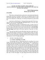
Bộ truyền bánh răng hành tinh
– Bằng cách sử dụng 2 bộ truyền bánh răng hành tinh
đã tạo ra hộp số tự động 6 cấp tốc độ.
F1
B2
B3
B1
: Ly hợp
:Phanh
C2
: Khớp 1 chiều
C1
Bộ bánh răng hành
tinh Ravigneaux
U660E, U760E
U250E
5
Model Outline
for Technician
Hộp số tự động
Engine
Chassis
Body
Body Electrical
-A -W -V -C
Hệ thống điều khiển điện tử
Điều khiển
U660E U760E
Điều khiển áp suất cắt nhả ly hợp
O
O
Điều khiển áp suất chuẩn
O
O
Điều khiển thời điểm khóa biến mơ
O
O
Điều khiển khởi động linh hoạt
O
O
Điều khiển khóa biến mơ linh hoạt
O
O
Điều khiển kết hợp truyền động
O
O
Điều khiển xuống số khi giảm tốc
O
O
Điều khiển xuống số trực tiếp
O
O
Điều khiển theo điều kiện đường
Điều khiển chuyển số
AI (Artificial Intelligent) Điều khiển theo ý định của người
lái
O
O
O
O
Hộp số tự động đa chế độ
O
O
Điều khiển số trung gian
—
O
Điều khiển khóa chuyển số
O
O
6
Model Outline
for Technician
Hộp số tự động
Engine
Chassis
Body
Body Electrical
-A -W -V -C
Điều khiển khởi động linh hoạt
– Điều khiển khởi động linh hoạt kích hoạt khóa biến
mơ linh hoạt khi xe bắt đầu chuyển động .
– Giảm tốc độ động cơ và cải thiện tính kinh tế nhiên
liệu.
: Điều khiển
: Khơng có điều
khiển
Kéo dài khóa biến
mơ linh hoạt
Tốc độ
động cơ
Tốc độ tuabin
Tốc độ xe
Thời gian
7
Model Outline
for Technician
Hộp số tự động
Engine
Chassis
Body
Body Electrical
-A -W -V -C
Điều khiển xuống số khi giảm tốc
– Điều khiển này duy trì tốc độ động cơ hợp lý và kéo dài
hoạt điều khiển cắt nhiên liệc lâu nhất có thể.
: Có điều khiển
ĐK cắt nhiên
liệu ON
Duy trì cắt nhiên liệu
: Khơng có điều khiển
ĐK cắt nhiên
liệu OFF
Tốc độ động cơ
6th
to 5th
to 4th
to 3rd*
to 5th
to 4th
to 3rd*
ĐK cắt nhiên
liệu ON
ĐK cắt nhiên
liệu OFF
Thời gian
*: Với hộp số U660 khơng có điều khiển ở số 3, 4
8
Model Outline
for Technician
Hộp số tự động
Engine
Chassis
Body
Body Electrical
-W -V -C
Điều khiển số trung gian
– Khi xe dừng trong khi cần số vẫn ở vị trí D,tải trên
động cơ sẽ giảm nhờ việc ngắt cơng suất từ động cơ
vào hộp số
Có điều khiển
Lượng phun: thấp
Khơng có điều khiển
Cải thiện tính kinh
tế nhiên liệu
Lượng phun : cao
Tổn thất
nhiệt: nhỏ
Tải động cơ:
thấp
Ly hợp:
Mở 1 nửa
Tổn thất
nhiệt : lớn
Tải động cơ :
cao
Ly hợp :
đóng
9
Model Outline
for Technician
Hộp số tự động
Engine
Chassis
Body
Body Electrical
-A -W -V -C
Hộp số tự động điều khiển đa chế độ
– Khi cần số ở vị trí S, dải số mặc định là S4 hoặc S5
tùy thuộc vào tốc độ của xe.
– Khi cần số giữ ở vị trí ”+” trong 1 giây hoặc hơn thì
dải số sẽ nhảy lên S6
Giữ >=1 s
1
2
3
4
5
6
- Dải số mặc định-
S
Tốc độ xe
10
Model Outline
for Technician
Hệ thống treo
Engine
Chassis
Body
Body Electrical
-A -W -V -C
Thông số kỹ thuật
– Góc đặt bánh xe
(Xe khơng chất tải)
Lốp
Vết bánh xe
[mm (in.)]
Caster
Trước
1588 (62.52)
1586*1 (62.44)
1589*2 (62.56)
2°55’
2°50’*1
Sau
1575 (62.00)
1574*3 (61.97)
1569*1 (61.77)
*1: Thị trường–A (Mexico)
*3: Thị trường –A
Camber
Toe-in
[mm (in.)]
Góc
nghiêng
trục lái
-0°40’
-0°35’*1
0 (0)
12°15’
12°05’*1
-1°10’
-1°00’*1
-1°15’*4
2.5 (0.10)
3.0*4 (0.12)
*2: Thị trường 2AR-FE
*4: Thị trường 2GR-FE for –C
Điều kiện chiều cao xe tiêu chuẩn
Trước
Sau
A-B=
121 mm (4.76 in.)
A
C-D=
46 mm (1.81 in.)
B
D
C
11
Model Outline
for Technician
Engine
Chassis
Tire Pressure Warning System
Body
Body Electrical
-A -W -V -C
Overall
– A direct-sensing type TPWS is used.
Model
Tire Pressure
Warning Valve
and Transmitter
Same as
GS350/250
New ES350/250
Previous ES350
Supplier
Pacific Industrial Co., LTD.
No. of Sensors
4 sensors / 5 sensors*1
ID Number
7-digit
Frequency
434 MHz
315 MHz*2
315 MHz (-A)
4 times / 60 sec. (at Driving)
1 time / 90 sec. (at Stopped)
1 time / 65 sec. (at
Driving / Stopped)
Shorten to 15 sec. in case of
change of 40 kPa or more
/ 30 sec.
•Door Control and Tire Pressure
Monitoring System Receiver*2
•Tire Pressure Monitor Receiver
Assembly
Tire Pressure
Warning System ECU
Supplier
DENSO
DTC Output
CAN
BEAN and CAN
Interval of Data Transmission
ECU
*1: Models with Full Size Spare Tire
*2: Models for -A and –C
12
Model Outline
for Technician
Engine
Chassis
Tire Pressure Warning System
Overall (Cont.)
– A direct-sensing type TPWS is used.
Body
Body Electrical
-A -W -V -C
Same as
GS350/250
Model
New ES350/250
Previous ES350
Tire Pressure Warning
Reset Switch
With
Tire Pressure Warning
Select Switch
Without
With
Antenna
1 (built into Receiver)
Auto-location Function
With
Without
Tire Pressure Display
Multi-information Display
Without
13
Model Outline
for Technician
Engine
Chassis
Tire Pressure Warning System
Body
Body Electrical
-A -W -V -C
System Diagram
Front Tire
Pressure
Warning
Initiator
Tire Pressure
Monitor Initiator
Driver
Rear Tire
Pressure
Warning
Initiator
Front Tire Pressure
Warning Valve and
Transmitter RH
Front Tire Pressure
Warning Valve and
Transmitter LH
Spare Tire Pressure
Warning Valve
and Transmitter*1
Rear Tire Pressure
Warning Valve and
Transmitter LH
Rear Tire Pressure
Warning Valve and
Transmitter RH
: Identification LF radio wave
*1: Models with Full Size Spare Tire
Tire Pressure
Warning Reset
Switch
Door Control
and
Tire Pressure
Monitoring
System
Receiver*2
Tire pressure
Monitor
Receiver
V Bus
Combination Meter
Tire Pressure
Warning Light
Multi-information
Display
DISP Switch
DLC3
Main Body ECU
(Instrument Panel
Junction Block)
: Information on radio field intensity
*2: Models for -A and -C
14
Model Outline
for Technician
Engine
Chassis
Body
Tire Pressure Warning System
Body Electrical
-A -W -V -C
Layout of Main Components
•Door Control and Tire Pressure
Monitoring System Receiver*1
•Tire pressure Monitor Receiver
*
Rear Tire
Pressure
Warning Initiator
Tire Pressure Warning
Valve and Transmitter
x 4 (x 5*2)
Front Tire Pressure
Warning Initiator
*1: Models for -A and -C
*2: Models with Full Size Spare Tire
15
Model Outline
for Technician
Engine
Chassis
Tire Pressure Warning System
Body
Body Electrical
-A -W -V -C
Layout of Main Components (Continued)
Multi-information
Display
Tire Pressure
Warning Light
Tire Pressure
Monitor Initiator
Driver
Main Body ECU
(Multiplex Network
Body ECU)
Tire Pressure
Warning Reset
Switch
DISP Switch
16
Model Outline
for Technician
Engine
Chassis
Tire Pressure Warning System
Body
Body Electrical
-A -W -V -C
Function of Main Components
Component
Function
Tire Pressure Warning
Valve and Transmitter
•Detects the tire pressure, internal temperature and rotational
acceleration of the tire and transmits the measured values and
the ID code to the tire pressure warning ECU and receiver.
•Receives electrical waves for tire position determination
from the initiators.
Tire Pressure Monitor
Initiator
Built into the front (rear)-left wheelhouse and
strengthens the electric waves of nearby sending devices
(tire pressure warning valve and transmitter).
Tire Pressure Monitor
Initiator Driver
Operates the tire pressure warning initiators.
Door Control and Tire
Pressure Monitoring
System Receiver*
Tire pressure Monitor
Receiver
•Receives the data from the tire pressure warning valve and
transmitter and monitors the tire inflation pressure.
•Outputs the respective signal to the main body ECU
(instrument panel junction block assembly) when a drop in the
tire inflation pressure, a system malfunction or the beginning
of initialization is detected.
•Instructs the initiator driver to determine tire positions.
•Confirms the positions of the tires in accordance with
the strength of the received electric waves, and sends a
signal to display the tire pressure value (based on the
measured value) on the multi-information display.
*: Models for -A and -C
17
Model Outline
for Technician
Engine
Chassis
Tire Pressure Warning System
Body
Body Electrical
-A -W -V -C
Function of Main Components (Continued)
Component
Tire Pressure Warning
Reset Switch
Main Body ECU
Combination
Meter
Tire
Pressure
Warning
Light
Function
The current tire pressures are stored in the tire pressure
warning system as set pressures when the tire pressure
warning reset switch is operated.
Receives the signal from tire pressure warning ECU and
receiver and outputs it to the combination meter assembly via
CAN communication.
•Illuminates or stays on after blinking for 1 minute to warn the
driver in accordance with the signal from the tire pressure
warning system.
•Flashes 3 times after initialization.
MultiDisplays the identified tire pressure and position to
information
inform or warn the driver.
Display
18
Model Outline
for Technician
Engine
Chassis
Tire Pressure Warning System
Body
Body Electrical
-A -W -V -C
Auto-location Function
– The system identifies the tire position by application of
distance attenuation of radio wave.
[Case of LF radio sent from Tire Pressure Monitor Front Initiator]
Rr RH
Fr RH
Door Control and
Tire Pressure
Monitoring System
Receiver Assembly
*1
Fr LH
: Identification LF radio wave
: Information on radio field
intensity
1
* : Tire Pressure Monitor
Initiator (Front / Rear)
*1
Rr LH
Tire Pressure Monitor Initiator Driver
[Radio field intensity which valve*2 receives]
Front
Rear
ID 1
Strong
Medium-intensity
ID 1
Fr LH
ID 2
Medium-intensity
Weak
ID 2
Fr RH
ID 3
Medium-intensity
Strong
ID 3
Rr LH
ID 4
Weak
Medium-intensity
ID 4
Rr RH
*2: Tire Pressure Warning Valve and Transmitter
Valve*2 Position
19
Model Outline
for Technician
Engine
Chassis
Tire Pressure Warning System
Body
Body Electrical
-A -W -V -C
Auto-location Function
– The multi-information display shows the following to
inform or warn the driver of the tire pressure.
– The display updates every 60 seconds.
Condition
Multiinformation
Display
Normal
*
Tire pressure is below
the warning threshold
*
System malfunction, or when
tire position identification
has not yet been completed
*
*: Models with Full Size Spare Tire
20
Model Outline
for Technician
Engine
Chassis
Tire Pressure Warning System
Body
Body Electrical
-A -W -V -C
Tire Pressure Monitor Initiator
– Built into the left wheelhouse and strengthens the
electric waves of nearby sending devices.
[Front]
[Rear]
Tire Pressure Monitor Initiator
Timing of position
Identification
• IG-ON.
• Vehicle start off (When the tire position cannot be identified
at the time of the engine switch is turned on (IG)).
• When the initialization is performed.
21
Model Outline
for Technician
Engine
Chassis
Tire Pressure Warning System
Body
Body Electrical
-A -W -V -C
Tire Pressure Monitor Initiator Driver
– Operates the tire pressure warning initiators.
ECU Integration
Box RH
Tire Pressure Monitor
Initiator Driver
22
Model Outline
for Technician
Engine
Chassis
Tire Pressure Warning System
Body
Body Electrical
-A -W -V -C
Tire Pressure
– Detection timing and method
• The tire pressure is displayed when the engine
switch is turned on (IG).
New ES350/250
Previous ES350
Possible
Impossible
Detects by IG-ON
Detection method
Two-way communication
between vehicle and tire
pressure warning valve and
transmitter
Periodically transmitted from
tire pressure warning valve
and transmitter
– Troubleshooting
Problem
Solution
Under certain conditions, the tire
pressure may not be displayed
By driving, a radio wave state becomes
good and displaying may be possible
When rotation is carry out with IG-ON,
• Carry out IG-ON OFF IG-ON
change of a position cannot to the
• Initialize the system
tire pressure is displayed
23
Model Outline
for Technician
Engine
Chassis
Tire Pressure Warning System
Body
Body Electrical
-A
-C
Tire Pressure
– Detection of Low tire pressure
• When the tire pressure becomes less than the alarm
pressure, the system illuminates the tire pressure
warning light to warn the driver.
Pressure
Tire
Pressure
Initialization
Initialization
Pressure
-25%
[Transmission Data]
Alarm
Performance
Release Pressure
Alarm Pressure
[Timing of Detection]
Time
Alarm Start
Initialization Pressure -25%
Alarm Release
Fill an air all the way up to Release Pressure
24
Model Outline
for Technician
Engine
Chassis
Tire Pressure Warning System
Body
Body Electrical
-W -V
Tire Pressure
– Detection of Low tire pressure
• Alarm Pressure and Release Pressure vary depending
on driving conditions (temperature of tire).
Pressure
Tire
Pressure
Release Pressure
Alarm Pressure
Initialization
Initialization
Pressure
-20%
Time
[Timing of Detection]
25