Fuel Injection Part 8 ppt
Bạn đang xem bản rút gọn của tài liệu. Xem và tải ngay bản đầy đủ của tài liệu tại đây (2.75 MB, 20 trang )
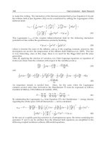
The investigation of the mixture formation upon fuel injection into high-temperature gas ows 133
Fig. 9. Isolines of air temperatures in the central longitudinal (a), transverse x = 0.28 (b) and
cross y = 0.95 (c) sections of the rectangular mixer of the rectangular mixer with jetty supply
of fuel (regime 1, U
1
= 0); α = 1.35
The calculations have shown that even in the absence of supply of the spraying air the gas
temperature depends substantially on the values of operating conditions. The distributions
of air temperatures in the absence and in the presence of a spraying air are presented in Figs.
9 and 10 - 11 respectively. Figure 9 characterizes the direct influence of heat exchange
519
579
629
679
729
769
809
839
849
859
879
869
889
899
889
639
689
739
799
879
899
869
799
819
779
759
739719
699
769
789
y
x
0 0,2 0,4 1.5 0,8 1 1,2 1,4
0,4
0,5
0,6
0.7
0,8
0,9
539
569
689
719
769
739
869
889
899
899
879
869
899
y
z
-0.2 0,1 0 0.1
0,6
0,7
0.7
0,9
489
589
669
709 739
759
769
779
789
819
859
879
899
889
849
839
799
749
679
849
739
739
729
779
799
829
849
869
889
899
899
829
849
x
z
0 0.2 0.4 0.6 0.8 1 1.2 1.4
-0.3
-0.2
-0.1
0
0.1
0.2
b
a
c
between the gas and droplets on temperature fields, since in the absence of this exchange air
has the same initial temperature over the entire region of flow. From the distributions of
temperatures in the longitudinal sections of the model it is seen that at α = 1.35 the region of
heat transfer at x = 1.6 extends in the direction of the y axis to the distance ∆y = 0.55. As
calculations showed, at α = 5.4 this distance is equal to ∆y = 0.42. The minimum
temperatures that correspond to these variants are equal to 447 and 683 K (Table 2). For the
variant α = 2.7 this quantity is equal to 539 K. Thus, on increase in the fuel flow rate through
a jet injector the influence of droplets on temperature fields becomes more and more
appreciable.
Fig. 10. Isolines of air temperatures in the central longitudinal section of the rectangular
mixer with pneumatic supply of fuel; spraying by a cold air jet (regime 2, U
1
= 20 m /s, T
1
=
300 K); a) α = 5.4; b) α = 1.35
As calculations show, on injection of a cold spraying air (Fig. 10), when heat transfer is
mainly determined by the interaction of the main and spraying flows, this effect is virtually
unnoticeable. When a hot spraying air is injected (T
1
= 900 K), heat transfer will again be
749
779
759
739
709
689
309
529
589
639
659
699
719
729
759
709
659
619
529
839
849
769
779
769
839
869
869
869
849
879
879
889
889
899
899
899
x
y
0 0.2 0.4 0.6 0.8 1 1.2 1.4
0.4
0.5
0.6
0.7
0.8
0.9
309
429
529
559
589
609
649
689
719
739
689
679
749
789
779
419
539
569
619
679
699
679
709
739
789
759
679
599
839
849
789
879
889
899
899
899
889
819
679
x
y
0 0,2 0,4 0,6 0,8 1 1,2 1,4
0,3
0,4
0,5
0,6
0,7
0,8
0,9
a
b
Fuel Injection134
determined by the interaction of air flows with droplets, and therefore the influence of the
fuel flow rate on the formation of temperature fields becomes appreciable (Table 2). The
corresponding graphs are presented in Fig. 11. It is seen that in these cases the influence of
droplets manifests itself virtually in the entire flow region.
Fig. 11. Isolines of air temperatures in the central longitudinal section of the rectangular
mixer with pneumatic supply of fuel; spraying by a hot air jet (regime 3, U
1
= 20 m /s,
T
1
= 900 K); a) α = 5.4; b) α = 1.35
Considering the model of heat transfer suggested in the present work, two moments must be
noted. The first is that the change in the gas temperature occurs owing to the transfer of heat
from the gas to droplets and is spent to heat and evaporate them. As calculations show, both
latter processes are essential despite the fact that the basic fraction of droplets (D
d
< 100 µm)
evaporates rather rapidly in the high-temperature air flow (T
1
= 900 K). The second moment is
that heating and evaporation are the mechanisms that underlie heat transfer in the very gas
phase and they are also two in number. The first is the conventional diffusion transfer of heat
and the second — its convective transfer due to secondary flows which are either initiated by
droplets or result from the flow of the stalling stream around the spraying air jets.
In the case of jetty supply of fuel the incipient secondary flows are of low intensity, and
droplets are weakly entrained by such flows. This is expressed as the absence of individual
899
899
899
889
889
879
879
879
869
869
869
879
879
859
849
839
839
819
799
799
739
869
x
y
0 0,2 0,4 0,6 0,8 1 1,2 1,4
0,4
0,5
0,6
0,7
0,8
0,9
529
679
739
659
849
889
899
899
889
879
869
859
819
749
789
809
819
799
789769
709
829
839
849
859
829
x
y
0 0.2 0.4 0.6 0.8 1 1.2 1.4
0,4
0,5
0,6
0.7
0,8
0,9
a
b
vortex structures in the distributions of both concentrations and temperatures in the
transverse sections of the module. The lowering of the gas temperature occurs exclusively at
the expense of interphase exchange. Vortex structures are clearly seen in transverse sections
with pneumatic spraying on the graphs of the distribution of fuel concentrations. A
comparison between the distributions of temperatures and concentrations in these cases
shows that the concentration profiles are much narrower than the corresponding
temperature profiles in both longitudinal and transverse directions. This is associated with
the intense diffusion heat fluxes, with the droplets mainly following the air flow. Attention
is also drawn to the fact that the penetrating ability of a "cold" fuel-air jet is higher than that
of a "hot" one due to the following two reasons: the great energy of the "cold" jet and the
more intense process of heating and evaporation of droplets in the "hot" jet.
A comparison of gas cooling in spraying of a fuel by a hot air jet and in jetty spraying shows
that although the fuel is injected into flows with identical temperatures, in the second case
the lowering of the gas temperature is more appreciable. This seems to be due to the fact
that on injection of droplets into a stalling air flow the velocity of droplets relative to the gas
is higher than in the case of injection into a cocurrent flow. The rate of the evaporation of
droplets is also higher and, consequently, the complete evaporation of droplets occurs over
smaller distances and in smaller volumes, thus leading to the effect noted. The total quantity
of heat transferred from air to droplets is the same in both cases, but the differences
observed allow one to make different fuel-air mixtures by supplying a fuel either into a
cocurrent air flow or into a stalling one.
(a) (b)
Fig. 12. Calculated vector velocity field in the longitudinal section of the axisymmetric
mixer; a) -
1
=
0
= 30, b)
1
=
0
= 60
The results of calculation for the axisymmetric mixer (fig. 1-b ) are presented in fig. 12 - 18. The
above-stated conclusions are applicable and to a flow beyond the coaxial tubes. However in
the case of the swirl the region of flow cooling significantly depends on the operating
conditions. This effect is connected with the absence or presence of paraxial reverse zone. The
velocity field in the vicinity of the place of fuel injection are given in fig. 12. As calculations
have shown, the basic role in formation of velocity fields is played by a swirl. In swirling
flows with
1
> 45 there occurs flow separated zone. Flow patterns at mixture of streams with
identical (T
1
= T
0
=900 K ) and various (T
1
= 300 K, T
0
=900 K ) temperature are almost the
The investigation of the mixture formation upon fuel injection into high-temperature gas ows 135
determined by the interaction of air flows with droplets, and therefore the influence of the
fuel flow rate on the formation of temperature fields becomes appreciable (Table 2). The
corresponding graphs are presented in Fig. 11. It is seen that in these cases the influence of
droplets manifests itself virtually in the entire flow region.
Fig. 11. Isolines of air temperatures in the central longitudinal section of the rectangular
mixer with pneumatic supply of fuel; spraying by a hot air jet (regime 3, U
1
= 20 m /s,
T
1
= 900 K); a) α = 5.4; b) α = 1.35
Considering the model of heat transfer suggested in the present work, two moments must be
noted. The first is that the change in the gas temperature occurs owing to the transfer of heat
from the gas to droplets and is spent to heat and evaporate them. As calculations show, both
latter processes are essential despite the fact that the basic fraction of droplets (D
d
< 100 µm)
evaporates rather rapidly in the high-temperature air flow (T
1
= 900 K). The second moment is
that heating and evaporation are the mechanisms that underlie heat transfer in the very gas
phase and they are also two in number. The first is the conventional diffusion transfer of heat
and the second — its convective transfer due to secondary flows which are either initiated by
droplets or result from the flow of the stalling stream around the spraying air jets.
In the case of jetty supply of fuel the incipient secondary flows are of low intensity, and
droplets are weakly entrained by such flows. This is expressed as the absence of individual
899
899
899
889
889
879
879
879
869
869
869
879
879
859
849
839
839
819
799
799
739
869
x
y
0 0,2 0,4 0,6 0,8 1 1,2 1,4
0,4
0,5
0,6
0,7
0,8
0,9
529
679
739
659
849
889
899
899
889
879
869
859
819
749
789
809
819
799
789769
709
829
839
849
859
829
x
y
0 0.2 0.4 0.6 0.8 1 1.2 1.4
0,4
0,5
0,6
0.7
0,8
0,9
a
b
vortex structures in the distributions of both concentrations and temperatures in the
transverse sections of the module. The lowering of the gas temperature occurs exclusively at
the expense of interphase exchange. Vortex structures are clearly seen in transverse sections
with pneumatic spraying on the graphs of the distribution of fuel concentrations. A
comparison between the distributions of temperatures and concentrations in these cases
shows that the concentration profiles are much narrower than the corresponding
temperature profiles in both longitudinal and transverse directions. This is associated with
the intense diffusion heat fluxes, with the droplets mainly following the air flow. Attention
is also drawn to the fact that the penetrating ability of a "cold" fuel-air jet is higher than that
of a "hot" one due to the following two reasons: the great energy of the "cold" jet and the
more intense process of heating and evaporation of droplets in the "hot" jet.
A comparison of gas cooling in spraying of a fuel by a hot air jet and in jetty spraying shows
that although the fuel is injected into flows with identical temperatures, in the second case
the lowering of the gas temperature is more appreciable. This seems to be due to the fact
that on injection of droplets into a stalling air flow the velocity of droplets relative to the gas
is higher than in the case of injection into a cocurrent flow. The rate of the evaporation of
droplets is also higher and, consequently, the complete evaporation of droplets occurs over
smaller distances and in smaller volumes, thus leading to the effect noted. The total quantity
of heat transferred from air to droplets is the same in both cases, but the differences
observed allow one to make different fuel-air mixtures by supplying a fuel either into a
cocurrent air flow or into a stalling one.
(a) (b)
Fig. 12. Calculated vector velocity field in the longitudinal section of the axisymmetric
mixer; a) -
1
=
0
= 30, b)
1
=
0
= 60
The results of calculation for the axisymmetric mixer (fig. 1-b ) are presented in fig. 12 - 18. The
above-stated conclusions are applicable and to a flow beyond the coaxial tubes. However in
the case of the swirl the region of flow cooling significantly depends on the operating
conditions. This effect is connected with the absence or presence of paraxial reverse zone. The
velocity field in the vicinity of the place of fuel injection are given in fig. 12. As calculations
have shown, the basic role in formation of velocity fields is played by a swirl. In swirling
flows with
1
> 45 there occurs flow separated zone. Flow patterns at mixture of streams with
identical (T
1
= T
0
=900 K ) and various (T
1
= 300 K, T
0
=900 K ) temperature are almost the
Fuel Injection136
same. The influence of the mean of spraying and the process of interaction of droplets with air
on the flow structure is practically unnoticeable for the cases considered.
In fig. 13 - 14 pictures of trajectories of the droplets projected on longitudinal section of the
mixer are resulted.
Fig. 13. Trajectories of the droplets in the axisymmetric mixer upon fuel injection into
isothermal swirling flows (spraying by pneumatic atomizer with spray angle 40);
T
0
= T
1
= 900 K; a)
1
=
0
= 30, b)
1
=
0
= 60
Fig. 14. Trajectories of the droplets in the axisymmetric mixer upon fuel injection into
nonisothermal swirling flows (spraying by pneumatic atomizer with spray angle 40); T
0
=
900 K; T
1
= 300 K; a)
1
=
0
= 30, b)
1
=
0
= 60
To various colors in drawing there correspond trajectories with various initial diameters of
droplets. From comparison of the presented pictures of trajectories it is visible, that
distinctions in interaction of a fuel spray with an air flow lead to significant differences in
distributions of drops in a working volume. In the case of reverse zone (fig. 13 b and 14 b)
droplets are shifted to the wall. The temperature mode also plays the important role in
formation of a fuel spray. It is visible, that at T
1
= T
0
= 900 K, owing to evaporation of drops,
their trajectories appear more shortly, than at motion in a flow with T
1
= 300 K. As
calculations have shown the influence of interphase exchange on trajectories and the
distribution of concentrations is insignificant.
(a) (b)
Fig. 15. Isolines of air temperatures in the longitudinal section of the axisymmetric mixer
upon fuel injection into isothermal swirling flows (spraying by pneumatic atomizer);
T
0
= T
1
= 900 K; - a) -
1
=
0
= 30, b)
1
=
0
= 60
899
891
8 03
795
859
835
x
r
0 0.2 0.4 0.6 0.8
0
0.1
0.2
0.3
r
803
811
819
811
899
899
89 1
89 1
883
875
86 7
859
85 1
843
5
82 7
x
0 0,1 0,2 0,3
0
0,1
0,2
0,3
a
b
So just as in the case of rectangular mixer it is possible to neglect the exchange of
momentum between the gas and droplets and to judge the interaction of droplets with an
air flow from temperature fields. It’s clear that the greatest cooling of a gas flow by droplets
occurs on the maximum gas temperature. The distributions of air temperatures on injection
of a hot spraying air are given in Fig. 15. That temperature fields to the full are determined
by the interaction of air flows with droplets. From comparison of drawings in fig 15 a) and
b) it is visible, that areas of influence of droplets on a gas flow are various also they are
determined in the core by flow hydrodynamics. In a case
1
=
0
= 30, the flow is no
separated and the area of cooling of gas is stretched along an axis. In a case
1
=
0
= 60
there exists the paraxial reverse zone. As result the last droplets are shifted to the wall
together with cooled gas. Analogous isothermals of gas at fuel spraying from one source
(supply by pressure atomizer) are resulted in fig. 16 a) and `16 b).
(a) (b)
Fig. 16. Isolines of air temperatures in the longitudinal section of the axisymmetric mixer
upon fuel injection into isothermal swirling flows (spraying by pressure atomizer ); T
0
= T
1
= 900 K; - a)
1
=
0
= 30, b)
1
=
0
= 60
a) (b)
Fig. 17. Isolines of air temperatures in the longitudinal section of the axisymmetric mixer
upon fuel injection into nonisothermal swirling flows (spraying by pneumatic atomizer);
T
0
= 900 K; T
1
= 300 K;
1
=
0
= 30; a) - without an interphase exchange; b) - taking into
account an interphase exchange
284
308
300
588
652
852
884
892
x
y
0 0.2 0.4 0.6 0.8
0
0.1
0.2
0.3
0.4
0.5
300
308
404 596
692
892
860
348
x
y
0 0.2 0.4 0.6 0.8
0
0.1
0.2
0.3
0.4
0.5
r
r
The investigation of the mixture formation upon fuel injection into high-temperature gas ows 137
same. The influence of the mean of spraying and the process of interaction of droplets with air
on the flow structure is practically unnoticeable for the cases considered.
In fig. 13 - 14 pictures of trajectories of the droplets projected on longitudinal section of the
mixer are resulted.
Fig. 13. Trajectories of the droplets in the axisymmetric mixer upon fuel injection into
isothermal swirling flows (spraying by pneumatic atomizer with spray angle 40);
T
0
= T
1
= 900 K; a)
1
=
0
= 30, b)
1
=
0
= 60
Fig. 14. Trajectories of the droplets in the axisymmetric mixer upon fuel injection into
nonisothermal swirling flows (spraying by pneumatic atomizer with spray angle 40); T
0
=
900 K; T
1
= 300 K; a)
1
=
0
= 30, b)
1
=
0
= 60
To various colors in drawing there correspond trajectories with various initial diameters of
droplets. From comparison of the presented pictures of trajectories it is visible, that
distinctions in interaction of a fuel spray with an air flow lead to significant differences in
distributions of drops in a working volume. In the case of reverse zone (fig. 13 b and 14 b)
droplets are shifted to the wall. The temperature mode also plays the important role in
formation of a fuel spray. It is visible, that at T
1
= T
0
= 900 K, owing to evaporation of drops,
their trajectories appear more shortly, than at motion in a flow with T
1
= 300 K. As
calculations have shown the influence of interphase exchange on trajectories and the
distribution of concentrations is insignificant.
(a) (b)
Fig. 15. Isolines of air temperatures in the longitudinal section of the axisymmetric mixer
upon fuel injection into isothermal swirling flows (spraying by pneumatic atomizer);
T
0
= T
1
= 900 K; - a) -
1
=
0
= 30, b)
1
=
0
= 60
899
891
8 03
795
859
835
x
r
0 0.2 0.4 0.6 0.8
0
0.1
0.2
0.3
r
803
811
819
811
899
899
89 1
89 1
883
875
86 7
859
85 1
843
5
82 7
x
0 0,1 0,2 0,3
0
0,1
0,2
0,3
a
b
So just as in the case of rectangular mixer it is possible to neglect the exchange of
momentum between the gas and droplets and to judge the interaction of droplets with an
air flow from temperature fields. It’s clear that the greatest cooling of a gas flow by droplets
occurs on the maximum gas temperature. The distributions of air temperatures on injection
of a hot spraying air are given in Fig. 15. That temperature fields to the full are determined
by the interaction of air flows with droplets. From comparison of drawings in fig 15 a) and
b) it is visible, that areas of influence of droplets on a gas flow are various also they are
determined in the core by flow hydrodynamics. In a case
1
=
0
= 30, the flow is no
separated and the area of cooling of gas is stretched along an axis. In a case
1
=
0
= 60
there exists the paraxial reverse zone. As result the last droplets are shifted to the wall
together with cooled gas. Analogous isothermals of gas at fuel spraying from one source
(supply by pressure atomizer) are resulted in fig. 16 a) and `16 b).
(a) (b)
Fig. 16. Isolines of air temperatures in the longitudinal section of the axisymmetric mixer
upon fuel injection into isothermal swirling flows (spraying by pressure atomizer ); T
0
= T
1
= 900 K; - a)
1
=
0
= 30, b)
1
=
0
= 60
a) (b)
Fig. 17. Isolines of air temperatures in the longitudinal section of the axisymmetric mixer
upon fuel injection into nonisothermal swirling flows (spraying by pneumatic atomizer);
T
0
= 900 K; T
1
= 300 K;
1
=
0
= 30; a) - without an interphase exchange; b) - taking into
account an interphase exchange
284
308
300
588
652
852
884
892
x
y
0 0.2 0.4 0.6 0.8
0
0.1
0.2
0.3
0.4
0.5
300
308
404 596
692
892
860
348
x
y
0 0.2 0.4 0.6 0.8
0
0.1
0.2
0.3
0.4
0.5
r
r
Fuel Injection138
During injection of a cold spraying air the heat transfer is determined both the interaction of
the main and spraying flows and the interaction of air flows with droplets. Gas isotherms in
this case are resulted on fig. 17 and 18, accordingly for
1
=
0
= 30 and
1
=
0
= 60.
(a) (b)
Fig. 18. Isolines of air temperatures in the longitudinal section of the axisymmetric mixer
upon fuel injection into nonisothermal swirling flows (spraying by pneumatic atomizer);
T
0
= 900 K; T
1
= 300 K;
1
=
0
=60; a) - without an interphase exchange; b) - taking into
account an interphase exchange
It is clear that in the considered cases heat exchange in the core is determined by interaction
of gas flows. The interphase exchange changes fields of temperatures only near to a fuel
supply place, i.e. in order area in the size 0.2 R
0
.
6. Conclusions
In all means of spraying, for the regimes considered it is possible to neglect the exchange of
momentum between the gas and droplets and to judge the interaction of droplets with an
air flow from temperature fields.
Injection of a fuel by a jet injector may cause a substantial change in the gas temperature. In
the given case it occurs due to heat transfer from the gas to droplets and is spent on their
heating and evaporation. In the case of pneumatic spraying of a fuel by a cold air jet the
influence of interphase exchange is insignificant. Heat transfer is predominantly determined
by the interaction of the main and spraying flows. During injection of a hot spraying air,
when heat transfer inside the gas flow is less intense, the influence of the injection of a fuel
on the formation of temperature fields again becomes appreciable. However, in this case the
gas is cooled less than in jetty spraying. This effect is due to the fact that when droplets are
injected into a stalling air flow, the rate of their evaporation is higher than during injection
into a cocurrent flow.
In the case of the swirl the region of flow cooling significantly depends on the operating
conditions. This effect is connected with the absence or presence of paraxial reverse zone.
The conclusions drawn confirm the necessity of taking into account the processes of
interphase heat and mass exchange when investigating the mixture formation.
r
r
284
300
396
564
7 16
884
892
x
y
0 0. 2 0.4 0.6 0 .8
0
0.1
0.2
0.3
0.4
0.5
812
668
5 40
444
452
3 08
3 24
3 00
0 0.2 0. 4 0.6 0.8 1
0
0.1
0.2
0.3
0.4
0.5
0.6
x
7. The further development of a calculation method
The further development of a computational technique should actuate the account of
coagulation and breakage of droplets. The calculations resulted below illustrate the
importance of turbulent coagulation of droplets of the spraying fuel behind injectors in
combustion chambers.
The main assumptions of physical character imposed on system coagulation of particles,
consist in the following. The number of particles is great enough, that it was possible to
apply function of distribution of particles on weights and in co-ordinate space. Only binary
collisions are considered, the collisions conserve the mass and volume, and the aerosol
particles coagulate each time they collide. Within the Smoluchowsky’s theoretical
framework (see Friedlander at al., 2000), at any time, each aerosol particle could be formed
by an integer number of base particles ( or monomers), which would be the smallest, simple
and stable particles in the aerosol, and the density of the number of particles with k
monomers, n
k
, as a function of time, would be the solution of the following balance
equation:
(17)
Non-negative function K
ij
is called as a coagulation kernel, it describes particular interaction
between particles with volumes i and j. The first term at the right hand side of Eq. (17) is the
production of the particles with k monomers due to collisions of particles with i and j
monomers such that i + j = k, and the second term is the consumption of particles with k
monomers due to collisions with other aerosol particles.
The majority of activities on coagulation research concern to atmospheric aerosols in which
this process basically is called by Brown diffusion. Still in sprays behind injectors the main
action calling increase of the sizes of drops, is turbulent coagulation. For such environments
the coagulation kernel can be recorded in the form of (Kruis & Kusters, 1997)
(18)
Here a
1
and a
2
- radiuses of particles i and j, W
s
- relative particle velocity due to inertial
turbulent effects and W
a
- relative particle velocity due to shear turbulent effects.
The system of equations (17-18) was solved by the finite-difference method (Maiharju, 2005).
As a result of the solution of the equations of turbulent coagulation it is investigated the
influence of ambient medium properties on growth rate of droplets behind the front
module. In particular the influence of speed of a dissipation of turbulent energy, the initial
size of droplets and ambient pressure on distribution of droplets in the sizes on various
distances behind an injector was investigated. The variation of the mean- median diameter
of droplets on time (distance from an injector) for droplets of the initial size 5 and 10
microns and normal ambient pressure is shown in fig. 19. The researches carried out have
shown that coagulation process can considerably change the sizes of droplets. The initial
diameter of droplets essentially influences coagulation process. So, at increase in the initial
The investigation of the mixture formation upon fuel injection into high-temperature gas ows 139
During injection of a cold spraying air the heat transfer is determined both the interaction of
the main and spraying flows and the interaction of air flows with droplets. Gas isotherms in
this case are resulted on fig. 17 and 18, accordingly for
1
=
0
= 30 and
1
=
0
= 60.
(a) (b)
Fig. 18. Isolines of air temperatures in the longitudinal section of the axisymmetric mixer
upon fuel injection into nonisothermal swirling flows (spraying by pneumatic atomizer);
T
0
= 900 K; T
1
= 300 K;
1
=
0
=60; a) - without an interphase exchange; b) - taking into
account an interphase exchange
It is clear that in the considered cases heat exchange in the core is determined by interaction
of gas flows. The interphase exchange changes fields of temperatures only near to a fuel
supply place, i.e. in order area in the size 0.2 R
0
.
6. Conclusions
In all means of spraying, for the regimes considered it is possible to neglect the exchange of
momentum between the gas and droplets and to judge the interaction of droplets with an
air flow from temperature fields.
Injection of a fuel by a jet injector may cause a substantial change in the gas temperature. In
the given case it occurs due to heat transfer from the gas to droplets and is spent on their
heating and evaporation. In the case of pneumatic spraying of a fuel by a cold air jet the
influence of interphase exchange is insignificant. Heat transfer is predominantly determined
by the interaction of the main and spraying flows. During injection of a hot spraying air,
when heat transfer inside the gas flow is less intense, the influence of the injection of a fuel
on the formation of temperature fields again becomes appreciable. However, in this case the
gas is cooled less than in jetty spraying. This effect is due to the fact that when droplets are
injected into a stalling air flow, the rate of their evaporation is higher than during injection
into a cocurrent flow.
In the case of the swirl the region of flow cooling significantly depends on the operating
conditions. This effect is connected with the absence or presence of paraxial reverse zone.
The conclusions drawn confirm the necessity of taking into account the processes of
interphase heat and mass exchange when investigating the mixture formation.
r
r
284
300
396
564
7 16
884
892
x
y
0 0. 2 0.4 0.6 0 .8
0
0.1
0.2
0.3
0.4
0.5
812
668
5 40
444
452
3 08
3 24
3 00
0 0.2 0. 4 0.6 0.8 1
0
0.1
0.2
0.3
0.4
0.5
0.6
x
7. The further development of a calculation method
The further development of a computational technique should actuate the account of
coagulation and breakage of droplets. The calculations resulted below illustrate the
importance of turbulent coagulation of droplets of the spraying fuel behind injectors in
combustion chambers.
The main assumptions of physical character imposed on system coagulation of particles,
consist in the following. The number of particles is great enough, that it was possible to
apply function of distribution of particles on weights and in co-ordinate space. Only binary
collisions are considered, the collisions conserve the mass and volume, and the aerosol
particles coagulate each time they collide. Within the Smoluchowsky’s theoretical
framework (see Friedlander at al., 2000), at any time, each aerosol particle could be formed
by an integer number of base particles ( or monomers), which would be the smallest, simple
and stable particles in the aerosol, and the density of the number of particles with k
monomers, n
k
, as a function of time, would be the solution of the following balance
equation:
(17)
Non-negative function K
ij
is called as a coagulation kernel, it describes particular interaction
between particles with volumes i and j. The first term at the right hand side of Eq. (17) is the
production of the particles with k monomers due to collisions of particles with i and j
monomers such that i + j = k, and the second term is the consumption of particles with k
monomers due to collisions with other aerosol particles.
The majority of activities on coagulation research concern to atmospheric aerosols in which
this process basically is called by Brown diffusion. Still in sprays behind injectors the main
action calling increase of the sizes of drops, is turbulent coagulation. For such environments
the coagulation kernel can be recorded in the form of (Kruis & Kusters, 1997)
(18)
Here a
1
and a
2
- radiuses of particles i and j, W
s
- relative particle velocity due to inertial
turbulent effects and W
a
- relative particle velocity due to shear turbulent effects.
The system of equations (17-18) was solved by the finite-difference method (Maiharju, 2005).
As a result of the solution of the equations of turbulent coagulation it is investigated the
influence of ambient medium properties on growth rate of droplets behind the front
module. In particular the influence of speed of a dissipation of turbulent energy, the initial
size of droplets and ambient pressure on distribution of droplets in the sizes on various
distances behind an injector was investigated. The variation of the mean- median diameter
of droplets on time (distance from an injector) for droplets of the initial size 5 and 10
microns and normal ambient pressure is shown in fig. 19. The researches carried out have
shown that coagulation process can considerably change the sizes of droplets. The initial
diameter of droplets essentially influences coagulation process. So, at increase in the initial
Fuel Injection140
size of drops with 5 m to 10m, the relative mean median diameter of droplets in 0.01
seconds is increased at 1.2 time (see fig. 19).
Fig. 19. The dependence of relative size of droplets in spray behind injector on coagulation
time; blue line - D
m0
= 5m; read line - D
m0
= 10 m
Fig. 20. The dependence of relative size of droplets in spray behind injector on combustion-
chamber pressure.
0 0.002 0.004 0.006 0.008 0.01
1
1.05
1.1
1.15
1.2
1.25
time [s]
Dm/Dmo
1 3 5 7 9 11 13 15 17 19 21
1
1.05
1.1
1.15
1.2
1.25
1.3
P, bar
Dm/Dmo
Fig. 21. The distribution of volumetric concentration on the sizes of droplets;
blue lines - initial distribution; red lines - distribution in 0.01 seconds; a) - = 1m
2
/s
3
;
b)
= 100m
2
/s
3
In fig. 20 data about influence of ambient pressure on coagulation of droplets of the
kerosene spray are resulted. Calculations are executed at value of
= 10m
2
/s
3
and initial
D
m
= 5m. It's evidently from the plot at pressure variation from 1 to 25 bar the mean size
of droplets as a result of coagulation for 0.01 seconds is increased approximately at 30 %.
Rate of a dissipation of turbulent energy is the essential parameter determining a kernel of
turbulent coagulation K (x, y). Estimations show, that behind front devices of combustion
chambers the value of rate of a turbulent energy dissipation varies from 1 to 100 m
2
/s
3
. In
drawings 21- a) and b) distributions of volumetric concentration C
f
for two values of a rate
of dissipation of turbulent energy are presented. The increase in dissipation leads to
displacement of distribution of volumetric concentration in area of the big sizes.0 So the
main fraction of drops of spraying liquid will fall to drops with sizes, 10 times magnitudes
surpassing initial drops.
Thus, ambient pressure, rate of dissipation of turbulence energy and the initial size of the
droplets leaving an injector make essential impact on coagulation of droplets.
It is necessary to note, that in disperse systems, except process of coagulation which
conducts to integration of particles, there are cases when the integrated particle breaks up
on small spontaneously or under the influence of external forces. Therefore coagulation
process will be accompanied by atomization of drops as a result of aerodynamic effect of air.
Thus as coagulation as breaking of droplets are desirable to take into account when
calculating the mixture formation.
8. Acknowledgement
This work was supported by the Russian Foundation for Basic Research, project No. 08-08-
00428.
10
-6
10
-4
10
-2
0
1
2
3
4
x 10
-3
Dm/2 [m]
Cf
a
10
-6
10
-4
10
-2
0
1
2
3
4
x 10
-3
Dm/2 [m]
Cf
b
The investigation of the mixture formation upon fuel injection into high-temperature gas ows 141
size of drops with 5 m to 10m, the relative mean median diameter of droplets in 0.01
seconds is increased at 1.2 time (see fig. 19).
Fig. 19. The dependence of relative size of droplets in spray behind injector on coagulation
time; blue line - D
m0
= 5m; read line - D
m0
= 10 m
Fig. 20. The dependence of relative size of droplets in spray behind injector on combustion-
chamber pressure.
0 0.002 0.004 0.006 0.008 0.01
1
1.05
1.1
1.15
1.2
1.25
time [s]
Dm/Dmo
1 3 5 7 9 11 13 15 17 19 21
1
1.05
1.1
1.15
1.2
1.25
1.3
P, bar
Dm/Dmo
Fig. 21. The distribution of volumetric concentration on the sizes of droplets;
blue lines - initial distribution; red lines - distribution in 0.01 seconds; a) - = 1m
2
/s
3
;
b)
= 100m
2
/s
3
In fig. 20 data about influence of ambient pressure on coagulation of droplets of the
kerosene spray are resulted. Calculations are executed at value of
= 10m
2
/s
3
and initial
D
m
= 5m. It's evidently from the plot at pressure variation from 1 to 25 bar the mean size
of droplets as a result of coagulation for 0.01 seconds is increased approximately at 30 %.
Rate of a dissipation of turbulent energy is the essential parameter determining a kernel of
turbulent coagulation K (x, y). Estimations show, that behind front devices of combustion
chambers the value of rate of a turbulent energy dissipation varies from 1 to 100 m
2
/s
3
. In
drawings 21- a) and b) distributions of volumetric concentration C
f
for two values of a rate
of dissipation of turbulent energy are presented. The increase in dissipation leads to
displacement of distribution of volumetric concentration in area of the big sizes.0 So the
main fraction of drops of spraying liquid will fall to drops with sizes, 10 times magnitudes
surpassing initial drops.
Thus, ambient pressure, rate of dissipation of turbulence energy and the initial size of the
droplets leaving an injector make essential impact on coagulation of droplets.
It is necessary to note, that in disperse systems, except process of coagulation which
conducts to integration of particles, there are cases when the integrated particle breaks up
on small spontaneously or under the influence of external forces. Therefore coagulation
process will be accompanied by atomization of drops as a result of aerodynamic effect of air.
Thus as coagulation as breaking of droplets are desirable to take into account when
calculating the mixture formation.
8. Acknowledgement
This work was supported by the Russian Foundation for Basic Research, project No. 08-08-
00428.
10
-6
10
-4
10
-2
0
1
2
3
4
x 10
-3
Dm/2 [m]
Cf
a
10
-6
10
-4
10
-2
0
1
2
3
4
x 10
-3
Dm/2 [m]
Cf
b
Fuel Injection142
9. Notation
C
f
, volumetric concentration of a liquid fuel, kg m
3
; c
f
, coefficient of specific heat of liquid, J
(kgK); c
pg
, coefficient of specific heat of gas at constant pressure, J (kgK); C
R
, coefficient of
droplet resistance; C
v
, concentration of fuel vapor per unit volume, kg m
3
; D
d
, droplet
diameter, m; D
m
, droplet mean median diameter, m; H, channel height, m; h, specific total
enthalpy, J kg; k, energy of turbulence per unit mass, m
2
s
2
; L, latent heat of evaporation, J
kg; m
d
, mass of a droplet, kg; m
f
, mass fraction of kerosene vapors; n
k
, density of the
number of particles with k monomers; Pr = µ
g
c
pg
λ
g
, Prandtl number;
, force of
aerodynamic resistance; Re = ρ
g
D
d
W µ
g
, Reynolds number of a droplet; S
, internal source
term in the equation of transfer of the variable
; T, temperature, K; t, time, s;
g, vector of
averaged gas velocity; U
gi
(i = 1, 2, 3), components of the vector of averaged gas velocity, m
/s;
d
, vector of droplet velocity;
=
d
−
g, vector of droplet velocity relative to gas; x, y, z,
Cartesian coordinates; x, r, , cylindrical coordinates; α, summed coefficient of air excess;
Γ
, coefficient of diffusion transfer of variable ; ∆t
d
, time of droplet residence in the
volume element, s; ∆v, elementary volume, m
3
; ε, rate of dissipation of turbulence energy,
m
2
s
3
; λ
g
, thermal conductivity of gas, W (mK); µ
g
, coefficient of dynamic viscosity of gas,
kg (ms); ρ, density, kg m
3
; , dependent variable;
1,
0
, wane angles of swirlers in inner
and outer channels, °. Subscripts and superscripts: 0, main flow; 1, spraying air; g, gas; f,
liquid fuel; d, droplet; int, interphase; v, vapor-like fuel; i, individual droplet.
10. References
Chien K.J. (1982). Predictions of channel and boundary-layer flows with low-Reynolds-
number turbulence model. AIAA J., Vol. 20, 33–38.
Dityakin Yu. F., Klyachko L. A., Novikov B. V. and V. I. Yagodkin. (1977). Spraying of Liquids
(in Russian), Mashinostroenie, Moscow.
Friedlander, S. K. (2000). Smoke, Dust and Haze. Oxford Univ. Press, Oxford.
Lefebvre A.H. (1985). Gas Turbine Combustion, Hemisphere Publishing corporation,
Washington, New York, London.
Koosinlin M.L., Launder B.E., Sharma B.J. (1974). Prediction of momentum, heat and mass
transfer in swirling turbulent boundary layers. Trans. ASME, Ser. C., Vol. 96, No 2,
204.
Kruis F. E & Kusters K.A. (1997) The Collision Rate of Particles in Turbulent Flow, Chem.
Eng. Comm. Vol. 158, 201-230.
Maiharju S.A (2005). Aerosol dynamics in a turbulent jet, A Thesis the Degree Master of Science in
the Graduate School of The Ohio State University.
Maiorova A.I. & Tretyakov V.V. (2008). Characteristic features of the process of mixture
formation upon fuel injection into a high-temperature air flow. Journal of
Engineering Physics and Thermophysics, Vol. 81, No. 2, 264-273. ISSN: 1062-0125.
Patankar S. (1980). Numerical Heat Transfer and Fluid Flow, Hemisphere Publishing, New
York.
Integrated numerical procedures for the design, analysis and optimization of diesel engines 143
Integrated numerical procedures for the design, analysis and optimization
of diesel engines
Daniela Siano, Fabio Bozza and Michela Costa
X
Integrated numerical procedures for the design,
analysis and optimization of diesel engines
Daniela Siano
1
, Fabio Bozza
2
and Michela Costa
1
1
Istituto Motori – CNR
2
DIME – Università di Napoli
ITALY
1. Introduction
Both the design and analysis of a diesel engine requires the integration of accurate
theoretical methods, resorting to 1D - 3D CFD modelling and vibro-acoustic engine analysis.
In this chapter, the above numerical approaches will be deeply presented and integrated to
perform a diesel engine design and/or analysis. As known in fact, the possibility to simulate
the physical and chemical processes characterising the operation of internal combustion
engines by using appropriate codes and high performance computers is continuously
spreading. These simulations can predict, as an example, fuel consumption, toxic emissions
and noise radiation. By varying the design and/or control parameters, different engine
configurations or working conditions can be tested and their performances compared.
Optimization techniques (Papalambros et al. 2000; Stephenson, 2008; Costa et al., 2009),
properly matched with the various simulation procedures, are hence the most suitable tool
to identify optimal solutions able to gain prescribed objectives on engine efficiency, power
output, noise, gas emissions, etc The choice of the optimization goal, moreover, strictly
depends on the application type and the definition of a compromise solution among the
conflicting needs is in many cases required.
Concerning the design of a combustion engine, a complicated and multi-objective task is to
be afforded, since it generally requires the fulfilment of various objectives and constraints,
as high efficiency and power output, low noise and gas emissions, low cost, high reliability,
etc. A tool for multi-objective optimization, therefore, can be considered as fundamental at
the engine design stage, in order to gain insight into the complicated relationships between
the physical entities involved in the design and design-dependent parameters. Ultimately,
optimization can greatly reduce the time-to-market of new engine prototypes.
Optimization techniques can successfully be applied to analyze the operating conditions of
existing engines, too. In this case, the optimization process can be focused on the selection of
the control parameters in order to obtain an optimal engine behaviour. It is well known, in
fact, that combustion development and emission production depend on a complex
interaction among different parameters, namely injection modulation and phasing (Stotz et
al. 2000), boost pressure, EGR fraction, swirl ratio, fuel properties, and so on. The optimal
choice of a so large number of parameters depends on speed and load conditions, and it is
8
Fuel Injection144
related to the fulfilment of a number of contrasting objectives, like reduced NOx, Soot, HC,
CO, fuel consumption and noise emissions.
In the present chapter the cited approach to the design and analysis of a diesel engine will
be explained. The discussion will be organized in the following paragraphs, each regarding
a different case study. In particular, the first paragraph is focused on the description of
single methodologies and to their integration:
• A 1D simulation of the whole propulsion system is realized by means of a proprietary
code. It allows to determine engine-turbocharger matching conditions and is able to
compute pressure, temperature and gas composition at the intake valve closure. The
latter data represent initial conditions for the successive 3D analysis.
• A 3D simulation of the engine cylinder is developed by exploiting geometrical
information derived by the engine CADs. The in-cylinder pressure cycle during the
closed valve period, is predicted, starting from the initial conditions provided by the
1D code.
• 1D or 3D computed pressure cycles are then utilized within vibro-acoustic analyses
aiming to estimate the combustion radiated noise. Depending on the application,
different approaches are followed:
• FEM-BEM approach: FEM analysis is applied to determine the vibration of the
engine skin surface; Direct Boundary Element Method (DBEM) solves the
exterior acoustic radiation according to the ISO directives, to predict the
radiated overall noise level. This method is utilised during the engine design
phase.
• Simplified approach: An analytical model based on the decomposition of in-
cylinder pressure cycles is developed to estimate the radiated noise level. Some
coefficients included in the above correlation are properly tuned to get a good
agreement with the acoustic experimental data. This method is applied during
the engine analysis phase.
• The numerical models are in different ways coupled to the optimization code, to
identify the optimal design parameters or the injection strategies, to the aim of
realizing the maximization of the engine performance, the reduction of the NOx and
soot emissions, and the reduction of the radiated noise, at a constant load and
rotational speed.
The second paragraph illustrates the design and optimization of a new two-stroke diesel
engine suitable for aeronautical applications. The engine, equipped with a Common Rail
fuel injection system, is conceived in a two-stroke uniflow configuration, aimed at achieving
a weight to power ratio equal to one kg/kW. Both CFD 1D and 3D analyses are carried out
to support the design phase and to address some particular aspects of the engine operation,
like the scavenging process, the engine-turbocharger matching, the fuel injection and the
combustion process. The exchange of information between the two codes allows to improve
the accuracy of the results. Computed pressure cycles are also utilized to numerically
predict the combustion noise, basing on the integration of FEM and BEM codes. The
obtained results are suitable to be used as driving parameters for successive engine
optimization. In order to improve the engine performance and vibro-acoustic behaviour, the
1D model, tuned with information derived from the 3D code, is linked to the optimization
code. A constrained multi-objective optimization is performed to contemporary minimize
the fuel consumption and the maximum in-cylinder temperature and pressure gradient
directly related to the noise emission. In this way a better selection of a number of engine
parameters is carried out (exhaust valve opening, closing and lift, intake ports heights, start
of injection, etc).
The third paragraph, indeed, describes an environmental and energetic optimization of a
naturally aspirated, light-duty direct injection (DI) diesel engine, equipped with a Common
Rail injection system. An experimental campaign is initially carried out to gain information
on performance and noise levels on the engine and to acquire the data required to validate
the 1D, the 3D model and the combustion noise procedure. As in the previous case, a
preliminary numerical simulation is carried out. Then, an optimization process is settled in
order to identify the control parameters of a three pulses injection profile, for a constant
overall mass of injected fuel. These parameters are assumed as independent variables of the
multi-objective optimization tool and are selected with the aim of simultaneously
minimizing fuel consumption, pollutant emissions and radiated noise.
2. Numerical Procedures
1D Simulation: the 1D simulation of the whole propulsion system is realized by means of
the 1Dime software developed at the Mechanical Engineering Department of the University
of Naples “Federico II” (Siano et al., 2008, Costa et al., 2009) and by exploiting geometrical
information of the intake and exhaust system derived by the engine CAD. The whole engine
is firstly schematized as a network of pipe and plenums, then, the 1D flow equations are
solved in each pipe constituting the intake and the exhaust system. The gas inside the
cylinder is indeed treated as a zero-dimensional thermodynamic system.
The code solves the 1D flow equations in the intake and exhaust pipes:
dx
d
ux
dx
d
ux
D
q
dx
d
uH
u
u
L
C
D
f
dx
d
u
dx
d
u
ux
ux
uH
pu
u
x
x
E
u
f
r
p
f
r
f
r
1
1
4
1
2
2
1
1
2
2
S F U
(1)
where , u, p, E=c
v
T+u
2
/2, H=c
p
T+u
2
/2 respectively represent the density, the velocity, the
pressure, and the total energy and enthalpy per unit mass. The source term S takes into
account the duct area variation along the flow direction, dΩ/dx, the wall heat exchange, q,
Integrated numerical procedures for the design, analysis and optimization of diesel engines 145
related to the fulfilment of a number of contrasting objectives, like reduced NOx, Soot, HC,
CO, fuel consumption and noise emissions.
In the present chapter the cited approach to the design and analysis of a diesel engine will
be explained. The discussion will be organized in the following paragraphs, each regarding
a different case study. In particular, the first paragraph is focused on the description of
single methodologies and to their integration:
• A 1D simulation of the whole propulsion system is realized by means of a proprietary
code. It allows to determine engine-turbocharger matching conditions and is able to
compute pressure, temperature and gas composition at the intake valve closure. The
latter data represent initial conditions for the successive 3D analysis.
• A 3D simulation of the engine cylinder is developed by exploiting geometrical
information derived by the engine CADs. The in-cylinder pressure cycle during the
closed valve period, is predicted, starting from the initial conditions provided by the
1D code.
• 1D or 3D computed pressure cycles are then utilized within vibro-acoustic analyses
aiming to estimate the combustion radiated noise. Depending on the application,
different approaches are followed:
• FEM-BEM approach: FEM analysis is applied to determine the vibration of the
engine skin surface; Direct Boundary Element Method (DBEM) solves the
exterior acoustic radiation according to the ISO directives, to predict the
radiated overall noise level. This method is utilised during the engine design
phase.
• Simplified approach: An analytical model based on the decomposition of in-
cylinder pressure cycles is developed to estimate the radiated noise level. Some
coefficients included in the above correlation are properly tuned to get a good
agreement with the acoustic experimental data. This method is applied during
the engine analysis phase.
• The numerical models are in different ways coupled to the optimization code, to
identify the optimal design parameters or the injection strategies, to the aim of
realizing the maximization of the engine performance, the reduction of the NOx and
soot emissions, and the reduction of the radiated noise, at a constant load and
rotational speed.
The second paragraph illustrates the design and optimization of a new two-stroke diesel
engine suitable for aeronautical applications. The engine, equipped with a Common Rail
fuel injection system, is conceived in a two-stroke uniflow configuration, aimed at achieving
a weight to power ratio equal to one kg/kW. Both CFD 1D and 3D analyses are carried out
to support the design phase and to address some particular aspects of the engine operation,
like the scavenging process, the engine-turbocharger matching, the fuel injection and the
combustion process. The exchange of information between the two codes allows to improve
the accuracy of the results. Computed pressure cycles are also utilized to numerically
predict the combustion noise, basing on the integration of FEM and BEM codes. The
obtained results are suitable to be used as driving parameters for successive engine
optimization. In order to improve the engine performance and vibro-acoustic behaviour, the
1D model, tuned with information derived from the 3D code, is linked to the optimization
code. A constrained multi-objective optimization is performed to contemporary minimize
the fuel consumption and the maximum in-cylinder temperature and pressure gradient
directly related to the noise emission. In this way a better selection of a number of engine
parameters is carried out (exhaust valve opening, closing and lift, intake ports heights, start
of injection, etc).
The third paragraph, indeed, describes an environmental and energetic optimization of a
naturally aspirated, light-duty direct injection (DI) diesel engine, equipped with a Common
Rail injection system. An experimental campaign is initially carried out to gain information
on performance and noise levels on the engine and to acquire the data required to validate
the 1D, the 3D model and the combustion noise procedure. As in the previous case, a
preliminary numerical simulation is carried out. Then, an optimization process is settled in
order to identify the control parameters of a three pulses injection profile, for a constant
overall mass of injected fuel. These parameters are assumed as independent variables of the
multi-objective optimization tool and are selected with the aim of simultaneously
minimizing fuel consumption, pollutant emissions and radiated noise.
2. Numerical Procedures
1D Simulation: the 1D simulation of the whole propulsion system is realized by means of
the 1Dime software developed at the Mechanical Engineering Department of the University
of Naples “Federico II” (Siano et al., 2008, Costa et al., 2009) and by exploiting geometrical
information of the intake and exhaust system derived by the engine CAD. The whole engine
is firstly schematized as a network of pipe and plenums, then, the 1D flow equations are
solved in each pipe constituting the intake and the exhaust system. The gas inside the
cylinder is indeed treated as a zero-dimensional thermodynamic system.
The code solves the 1D flow equations in the intake and exhaust pipes:
dx
d
ux
dx
d
ux
D
q
dx
d
uH
u
u
L
C
D
f
dx
d
u
dx
d
u
ux
ux
uH
pu
u
x
x
E
u
f
r
p
f
r
f
r
1
1
4
1
2
2
1
1
2
2
S F U
(1)
where , u, p, E=c
v
T+u
2
/2, H=c
p
T+u
2
/2 respectively represent the density, the velocity, the
pressure, and the total energy and enthalpy per unit mass. The source term S takes into
account the duct area variation along the flow direction, dΩ/dx, the wall heat exchange, q,
Fuel Injection146
and the friction losses. The last two equations describe the scalar transport of chemical
species, x
r
and x
f
being the residual gases and fuel mass fraction, respectively. These
equations allow to compute the composition of the gases flowing in the intake and exhaust
systems and therefore to estimate also the in-cylinder charge composition.
In the case of turbocharged engine, the performance maps of the turbocharger group are
employed to compute the engine-turbocharger matching.
Concerning the modeling of the combustion process, a classical Wiebe equation is utilized to
compute the heat release rate in the engine. Proper values of the combustion process
duration during both premixed and diffusive phases are specified. This preliminary
approach is substituted in the following by the more detailed 3D analysis later described.
-360 -270 -180 -90 0 90 180 270 360
C
r
ank Angle, deg
0
10
20
30
40
50
60
70
Pressure, bar
Exp.
1D Results
1500 rpm, BMEP=1.5 bar
C1
C2
C3
C4
C5
C6
-360 -270 -180 -90 0 90 180 270 360
Crank Angle, deg
0
10
20
30
40
50
60
70
Pressure, bar
Exp.
1D Results
2500 rpm, BMEP=2.5 bar
C1
C2
C3
C4
C5
C6
Fig. 1. 1D computed pressure cycles in different operating conditions
As an example, Figure 1 displays the comparison between computed and experimental
pressure cycles in a turbocharged six cylinders engine, for two different operating
conditions. The agreement along the compression stroke indicates that a good engine-
turbocharger matching can be reached. Starting from the computed initial conditions at IVC,
the 3D model is expected to further improve combustion phase analysis.
3D Simulation: The AVL FIRE™ 3D code is employed. It represents a multipurpose tool,
specially conceived for engine applications. The first step of the analysis concerns the
generation of the 3D domain representing the computational grid. This is effected by means
of the semi-automatic procedure of the code, named Fame Advanced Hybrid, which allows
to reach a good compromise between accuracy and reduced number of cells. The
computational period is subdivided into intervals, each pertinent to a grid of a chosen size,
that is deformed as the piston moves until predefined crank angles, starting from which
new grids with different sizes are used. This occurs through a procedure of re-mapping of
the computed variables, termed rezone, avoiding an excessive cells deformation. Within
each cell, the Reynolds Averaged Navier-Stokes equations are numerically solved to
compute the 3D flow field and the thermodynamic conditions inside the cylinder. The CFD
analysis accounts for the fuel spray dynamics and for the subsequent chemical reactions,
leading to the prediction of the rate of heat release (Colin and Benkenida, 2004) , pollutants
formation and in-cylinder pressure cycle.
The fuel spray spatio-temporal dynamics is simulated according to a Discrete Droplets
Model (DDM) (Liu and Reitz, 1993; O’Rourke. 1989; Dukowicz, 1980), where the Eulerian
description of the gaseous phase is coupled with a Lagrangian approach to the study of the
liquid flow. Modelling of spray accounts for primary and secondary atomization,
evaporation, coalescence, turbulence effects and possible cavitation within the nozzle.
Examples of spray, combustion and emission calculations will be presented in paragraphs 2
and 3, with reference to selected case studies.
Despite the modelling of the combustion and noxious emission, the 3D code can be also
employed to improve the accuracy of the previously described 1D model through the
theoretical evaluation of the discharge coefficients through valves or ports. The above values
are usually derived from literature information in 1D modelling and, of course, the related
accuracy is limited. Alternatively, the latter can be evaluated by numerically simulating the
3D air flow within the engine intake system. The computation is performed under the
hypothesis of steady conditions, in such a way to reproduce a possible experiment realisable
over a flow rate test bench. An example grid used for this kind of analysis is shown in
Figure 2. It refer to a two-stroke engine more deeply described in paragraph 2 and clearly
exhibits the geometrical characteristics of the air admission volume, with one inflow duct
and the three cylinders of a bank placed with their axes in the direction orthogonal to that of
the air inflow. Only the central cylinder is considered as opened. The volume corresponding
to the intake ports of the central cylinder is meshed, those of the lateral cylinders are not
included in the computational domain for the sake of simplicity. The total number of cells is
518346, 330746 of which are hexahedrical, thus assuring a certain grid regularity. The
fourteen ports of the central cylinder form one block with an external cylindrical area,
whose design follows the geometric characteristics of the cylinder jacket. The grid in this
zone, quite well visible in Figure 2, is made particularly thick, since it comprehends 148415
cells. Computation is performed for fixed values of the entering air mass flow rate and
always setting the static pressure and temperature at the outlet section equal to atmospheric
conditions. The ports are opened to the 100%, 75%, 50% and 25% for a mass flow rate
ranging from 0.03 to 0.15 kg/s.
Figure 3 shows a view of the velocity magnitude distribution obtained as a result of the
calculation for intake ports completely opened. The velocity vector magnitude is considered
Integrated numerical procedures for the design, analysis and optimization of diesel engines 147
and the friction losses. The last two equations describe the scalar transport of chemical
species, x
r
and x
f
being the residual gases and fuel mass fraction, respectively. These
equations allow to compute the composition of the gases flowing in the intake and exhaust
systems and therefore to estimate also the in-cylinder charge composition.
In the case of turbocharged engine, the performance maps of the turbocharger group are
employed to compute the engine-turbocharger matching.
Concerning the modeling of the combustion process, a classical Wiebe equation is utilized to
compute the heat release rate in the engine. Proper values of the combustion process
duration during both premixed and diffusive phases are specified. This preliminary
approach is substituted in the following by the more detailed 3D analysis later described.
-360 -270 -180 -90 0 90 180 270 360
C
r
ank Angle, deg
0
10
20
30
40
50
60
70
Pressure, bar
Exp.
1D Results
1500 rpm, BMEP=1.5 bar
C1
C2
C3
C4
C5
C6
-360 -270 -180 -90 0 90 180 270 360
Crank Angle, deg
0
10
20
30
40
50
60
70
Pressure, bar
Exp.
1D Results
2500 rpm, BMEP=2.5 bar
C1
C2
C3
C4
C5
C6
Fig. 1. 1D computed pressure cycles in different operating conditions
As an example, Figure 1 displays the comparison between computed and experimental
pressure cycles in a turbocharged six cylinders engine, for two different operating
conditions. The agreement along the compression stroke indicates that a good engine-
turbocharger matching can be reached. Starting from the computed initial conditions at IVC,
the 3D model is expected to further improve combustion phase analysis.
3D Simulation
: The AVL FIRE™ 3D code is employed. It represents a multipurpose tool,
specially conceived for engine applications. The first step of the analysis concerns the
generation of the 3D domain representing the computational grid. This is effected by means
of the semi-automatic procedure of the code, named Fame Advanced Hybrid, which allows
to reach a good compromise between accuracy and reduced number of cells. The
computational period is subdivided into intervals, each pertinent to a grid of a chosen size,
that is deformed as the piston moves until predefined crank angles, starting from which
new grids with different sizes are used. This occurs through a procedure of re-mapping of
the computed variables, termed rezone, avoiding an excessive cells deformation. Within
each cell, the Reynolds Averaged Navier-Stokes equations are numerically solved to
compute the 3D flow field and the thermodynamic conditions inside the cylinder. The CFD
analysis accounts for the fuel spray dynamics and for the subsequent chemical reactions,
leading to the prediction of the rate of heat release (Colin and Benkenida, 2004) , pollutants
formation and in-cylinder pressure cycle.
The fuel spray spatio-temporal dynamics is simulated according to a Discrete Droplets
Model (DDM) (Liu and Reitz, 1993; O’Rourke. 1989; Dukowicz, 1980), where the Eulerian
description of the gaseous phase is coupled with a Lagrangian approach to the study of the
liquid flow. Modelling of spray accounts for primary and secondary atomization,
evaporation, coalescence, turbulence effects and possible cavitation within the nozzle.
Examples of spray, combustion and emission calculations will be presented in paragraphs 2
and 3, with reference to selected case studies.
Despite the modelling of the combustion and noxious emission, the 3D code can be also
employed to improve the accuracy of the previously described 1D model through the
theoretical evaluation of the discharge coefficients through valves or ports. The above values
are usually derived from literature information in 1D modelling and, of course, the related
accuracy is limited. Alternatively, the latter can be evaluated by numerically simulating the
3D air flow within the engine intake system. The computation is performed under the
hypothesis of steady conditions, in such a way to reproduce a possible experiment realisable
over a flow rate test bench. An example grid used for this kind of analysis is shown in
Figure 2. It refer to a two-stroke engine more deeply described in paragraph 2 and clearly
exhibits the geometrical characteristics of the air admission volume, with one inflow duct
and the three cylinders of a bank placed with their axes in the direction orthogonal to that of
the air inflow. Only the central cylinder is considered as opened. The volume corresponding
to the intake ports of the central cylinder is meshed, those of the lateral cylinders are not
included in the computational domain for the sake of simplicity. The total number of cells is
518346, 330746 of which are hexahedrical, thus assuring a certain grid regularity. The
fourteen ports of the central cylinder form one block with an external cylindrical area,
whose design follows the geometric characteristics of the cylinder jacket. The grid in this
zone, quite well visible in Figure 2, is made particularly thick, since it comprehends 148415
cells. Computation is performed for fixed values of the entering air mass flow rate and
always setting the static pressure and temperature at the outlet section equal to atmospheric
conditions. The ports are opened to the 100%, 75%, 50% and 25% for a mass flow rate
ranging from 0.03 to 0.15 kg/s.
Figure 3 shows a view of the velocity magnitude distribution obtained as a result of the
calculation for intake ports completely opened. The velocity vector magnitude is considered
Fuel Injection148
over a plane orthogonal to the cylinders axes, cutting the intake ports exit section in the
middle. Air velocity distributes non-uniformly over the fourteen ports surfaces: the seven
ports which are closer to the air inflow duct are better served and mainly contribute to fill
the cylinder with the fresh charge. The velocity in correspondence of the other seven ports
maintains lower. The shape of the ports, with their surfaces positioned in tangential
direction with respect to the cylinder external surface, allows a swirl motion of the air
entering the cylinder.
Fig. 2. Grid employed for the evaluation of the intake ports discharge coefficient.
Fig. 3. Velocity field on a plane orthogonal to the cylinder axis
The results of the computations allow the determination of the discharge coefficient as the
ratio between the effective mass flow rate,
eff
m
, and the theoretical one,
th
m
:
th
eff
D
m
m
C
(2)
The theoretical mass flow rate is evaluated as a function of inlet pressure and temperature
and flow area, corresponding to the imposed effective mass flow rate.
Figure 4 summarises the results of the calculation for various surface percentages in the
opening of the intake ports. The discharge coefficient maintains almost constant with the
entering mass flow rate and ranges between about 0.6 and 0.98, due to the reduction of the
exit section area used for the evaluation of the theoretical mass flow rate. These results will
be directly employed in the 1D model, for accuracy improvement.
0 0.04 0.08 0.12 0.16
mass flow
r
a
t
e
(
k
g
/
s
)
0
0.2
0.4
0.6
0.8
1
Intake ports discharge coefficient
Port opening 100%
Port opening 75%
Port opening 50%
Port opening 25%
Fig. 4. Discharge coefficients evaluated for various opening of the intake ports.
Vibro-acoustic analyses: a FEM analysis is conducted in order to evaluate the engine
surface vibrations induced by the combustion process evolution. The previously predicted
pressure cycle is employed in this phase to compute the forces acting on the internal
structure. The obtained vibrational output data represent the boundary conditions to be
applied to the BEM code for the final evaluation of the radiated sound power. The selected
codes to evaluate the sound radiation noise from the engine block surface are the
MSC/Nastran
TM
and LMS/Sysnoise
TM
. Both approaches require the development of a
detailed 3D mesh and are very time-consuming. For this reason, this detailed methodology
cannot be directly applied within the optimization loop. Additional insights of the above
summarized approach will be given in paragraph 2.
Alternatively, a simplified and recently proposed methodology (Torregrosa et al., 2007;
Payri et al., 2005) can be utilized for the prediction of the overall combustion noise, which
Integrated numerical procedures for the design, analysis and optimization of diesel engines 149
over a plane orthogonal to the cylinders axes, cutting the intake ports exit section in the
middle. Air velocity distributes non-uniformly over the fourteen ports surfaces: the seven
ports which are closer to the air inflow duct are better served and mainly contribute to fill
the cylinder with the fresh charge. The velocity in correspondence of the other seven ports
maintains lower. The shape of the ports, with their surfaces positioned in tangential
direction with respect to the cylinder external surface, allows a swirl motion of the air
entering the cylinder.
Fig. 2. Grid employed for the evaluation of the intake ports discharge coefficient.
Fig. 3. Velocity field on a plane orthogonal to the cylinder axis
The results of the computations allow the determination of the discharge coefficient as the
ratio between the effective mass flow rate,
eff
m
, and the theoretical one,
th
m
:
th
eff
D
m
m
C
(2)
The theoretical mass flow rate is evaluated as a function of inlet pressure and temperature
and flow area, corresponding to the imposed effective mass flow rate.
Figure 4 summarises the results of the calculation for various surface percentages in the
opening of the intake ports. The discharge coefficient maintains almost constant with the
entering mass flow rate and ranges between about 0.6 and 0.98, due to the reduction of the
exit section area used for the evaluation of the theoretical mass flow rate. These results will
be directly employed in the 1D model, for accuracy improvement.
0 0.04 0.08 0.12 0.16
mass flow
r
a
t
e
(
k
g
/
s
)
0
0.2
0.4
0.6
0.8
1
Intake ports discharge coefficient
Port opening 100%
Port opening 75%
Port opening 50%
Port opening 25%
Fig. 4. Discharge coefficients evaluated for various opening of the intake ports.
Vibro-acoustic analyses
: a FEM analysis is conducted in order to evaluate the engine
surface vibrations induced by the combustion process evolution. The previously predicted
pressure cycle is employed in this phase to compute the forces acting on the internal
structure. The obtained vibrational output data represent the boundary conditions to be
applied to the BEM code for the final evaluation of the radiated sound power. The selected
codes to evaluate the sound radiation noise from the engine block surface are the
MSC/Nastran
TM
and LMS/Sysnoise
TM
. Both approaches require the development of a
detailed 3D mesh and are very time-consuming. For this reason, this detailed methodology
cannot be directly applied within the optimization loop. Additional insights of the above
summarized approach will be given in paragraph 2.
Alternatively, a simplified and recently proposed methodology (Torregrosa et al., 2007;
Payri et al., 2005) can be utilized for the prediction of the overall combustion noise, which
Fuel Injection150
includes in the correlation a strict dependency on the engine operating conditions and
injection strategy. The main idea behind this technique is the decomposition of the total in-
cylinder pressure signal according to three main contributions: compression-expansion,
combustion and resonance pressures:
rescombmottot
pppp (3)
The first contribution (also referred as pseudo-motored signal) is only related to volume
variation, and is used as a reference signal. It is determined by a direct in-cylinder pressure
acquisition during a fuel switch-off operation. The third term (resonance pressure) is indeed
related to high-frequency pressure fluctuations, induced by the wave reflections in the
combustion chamber, mainly occurring at autoignition time. It is computed through a high
pass-band filter (above 4500 Hz) of the total pressure signal. By difference, the combustion
pressure (second term in eq. 3) can be easily determined, too. The three terms in eq. 3 are
reported for comparison in figure 5. Despite the presence of the previously discussed high-
frequency amplitudes, the resonant pressure is significantly lower than other contributions.
Nevertheless, it may still exert a non-negligible effect on the overall noise.
-90 -60 -30 0 30 60 90
Crank
A
ngle, [deg]
0
25
50
75
100
Pressure [bar]
Total Pressure
Motored
Combustion
Resonance
-20 -10 0 10 20
Crank Angle [deg]
-0.4
-0.2
0
0.2
0.4
0.6
Pressure [bar]
Resonance Pressure
Fig. 5. Decomposition of the total pressure in motored, combustion and resonance
contributions.
The three decomposed pressures are utilized to compute two characteristic indices I
1
and I
2
defined as:
mot
combcomb
idle
dt
dp
dt
dp
dt
dp
n
n
I
max
2max1max
1
(4)
dtp
dtp
I
mot
res
2
2
6
102
10log
(5)
The I
1
index is a function of the maximum pressure gradient of the combustion contribution,
occurring after the pilot (dp
max1
/dt)c
omb
and the main injection (dp
max2
/dt)
comb
. The I
1
index
is also non-dimensionalized over the maximum pressure gradient of the pseudo-motored
pressure (dp
max
/dt)
mot
. In the case of a single-shot injection, a unique term is of course
present in the eq. (4) numerator. The I
2
index takes into account the acoustic energies (∫p
2
dt)
associated with resonance and motored pressure signals. An additional index In is finally
defined accounting for mechanical noise contribution, related, as stated, to the sole engine
speed:
n
idle
n
I
n
10
log
(6)
n being the engine speed and n
idle
the idle rotational speed.
Basing on the above definitions, the Overall Noise (ON) can be finally computed as:
22110
ICICICCON
nn
(7)
C
i
being proper tuning constants, depending on the engine architecture and size.
Following the relations (4-7), a Matlab routine was developed to properly process the in-
cylinder pressure cycle and compute the various noise indices and the overall noise.
The method is validated on acoustic measurements taken on a commercial engine, as
reported in figure 6. The agreement obtained is satisfactory at each engine speed. A
maximum absolute error of about 1.3 dB is found at a medium engine regime.
1200 1600 2000 2400 2800 3200
Engine Speed [rpm]
90
95
100
105
110
115
Overall Noise [dB]
Exp
Calc
Fig. 6. Comparisons on the overall noise
Integrated numerical procedures for the design, analysis and optimization of diesel engines 151
includes in the correlation a strict dependency on the engine operating conditions and
injection strategy. The main idea behind this technique is the decomposition of the total in-
cylinder pressure signal according to three main contributions: compression-expansion,
combustion and resonance pressures:
rescombmottot
pppp (3)
The first contribution (also referred as pseudo-motored signal) is only related to volume
variation, and is used as a reference signal. It is determined by a direct in-cylinder pressure
acquisition during a fuel switch-off operation. The third term (resonance pressure) is indeed
related to high-frequency pressure fluctuations, induced by the wave reflections in the
combustion chamber, mainly occurring at autoignition time. It is computed through a high
pass-band filter (above 4500 Hz) of the total pressure signal. By difference, the combustion
pressure (second term in eq. 3) can be easily determined, too. The three terms in eq. 3 are
reported for comparison in figure 5. Despite the presence of the previously discussed high-
frequency amplitudes, the resonant pressure is significantly lower than other contributions.
Nevertheless, it may still exert a non-negligible effect on the overall noise.
-90 -60 -30 0 30 60 90
Crank
A
ngle, [deg]
0
25
50
75
100
Pressure [bar]
Total Pressure
Motored
Combustion
Resonance
-20 -10 0 10 20
Crank Angle [deg]
-0.4
-0.2
0
0.2
0.4
0.6
Pressure [bar]
Resonance Pressure
Fig. 5. Decomposition of the total pressure in motored, combustion and resonance
contributions.
The three decomposed pressures are utilized to compute two characteristic indices I
1
and I
2
defined as:
mot
combcomb
idle
dt
dp
dt
dp
dt
dp
n
n
I
max
2max1max
1
(4)
dtp
dtp
I
mot
res
2
2
6
102
10log
(5)
The I
1
index is a function of the maximum pressure gradient of the combustion contribution,
occurring after the pilot (dp
max1
/dt)c
omb
and the main injection (dp
max2
/dt)
comb
. The I
1
index
is also non-dimensionalized over the maximum pressure gradient of the pseudo-motored
pressure (dp
max
/dt)
mot
. In the case of a single-shot injection, a unique term is of course
present in the eq. (4) numerator. The I
2
index takes into account the acoustic energies (∫p
2
dt)
associated with resonance and motored pressure signals. An additional index In is finally
defined accounting for mechanical noise contribution, related, as stated, to the sole engine
speed:
n
idle
n
I
n
10
log
(6)
n being the engine speed and n
idle
the idle rotational speed.
Basing on the above definitions, the Overall Noise (ON) can be finally computed as:
22110
ICICICCON
nn
(7)
C
i
being proper tuning constants, depending on the engine architecture and size.
Following the relations (4-7), a Matlab routine was developed to properly process the in-
cylinder pressure cycle and compute the various noise indices and the overall noise.
The method is validated on acoustic measurements taken on a commercial engine, as
reported in figure 6. The agreement obtained is satisfactory at each engine speed. A
maximum absolute error of about 1.3 dB is found at a medium engine regime.
1200 1600 2000 2400 2800 3200
Engine Speed [rpm]
90
95
100
105
110
115
Overall Noise [dB]
Exp
Calc
Fig. 6. Comparisons on the overall noise
Fuel Injection152
The method can be applied to both experimental and numerical pressure cycles and strictly
depends on the engine operating conditions and injection strategy. Once validated, this
simplified approach is directly included in the optimization loop to predict the overall noise.
Optimization process
: the briefly described 1D, 3D and acoustic tools are coupled together
within an optimization loop searching for design or control parameters minimizing fuel
consumption, gaseous emissions and radiated noise. The logical development of the
optimization problem is developed within the ModeFRONTIER
TM
environment. For each
set of the design or control parameters, the 1D, 3D and acoustic tools are automatically
started. 1D results allow to run the 3D code from reliable conditions at the intake valve
closure. Then, the 3D computed pressure cycle is automatically given in input to a Matlab
TM
routine computing the overall combustion noise. Simultaneously, the Indicated Mean
effective pressure (IMEP), is returned back to the optimizer, together with the NO and soot
levels at the end of the 3D run. A multi-objective optimization is so defined to
contemporarily search the maximum IMEP, the minimum soot, the minimum NO and the
minimum overall noise. To solve the above problem, genetic algorithms (Sasaki, 2005) are
usually utilized, employing a range adaptation technique to overcome time-consuming
evaluations. As usual in multi-objective optimization problems, a multiplicity of solutions is
expected, belonging to the so-called Pareto frontiers. In order to select a single optimal
solution among the Pareto-frontier ones, the “Multi Criteria Decision Making” tool (MCDM)
provided in modeFRONTIER
TM
is employed. This allows the definition of preferences
expressed by the user through direct specification of attributes of importance (weights)
among the various objectives. Depending on these relations, the MCDM tool is able to
classify all the solutions with a rank value. The highest rank solution is the one that better
satisfies the preference set.
In the following paragraphs, two examples are presented where the described methodology
is applied to perform the design of a Two-Stroke Engine for aeronautical application and to
select an optimal fuel injection strategy for a light-duty automotive engine.
3. Optimal Design of a Two-Stroke Engine for aeronautical application
In this paragraph, some aspects concerning the development of a prototype of a diesel
engine suitable for aeronautical applications are discussed (Siano et al., 2008). The engine
aimed at achieving a weight to power ratio equal to one kg/kW (220 kg for 220 kW) is
conceived in a two stroke Uniflow configuration and is constituted by six cylinders
distributed on two parallel banks. Basing on a first choice of some geometrical and
operational data, a preliminary fluid-dynamic and acoustic analysis is carried out at the sea
level. This includes the engine-turbocharger matching, the estimation of the scavenging
process efficiency, and the simulation of the spray and combustion process, arising from a
Common Rail injection system. Both 1D and 3D CFD models are employed.
A CAD of the engine under investigation is shown in figure 7. Six cylinders are distributed
on two parallel banks with separate air admission. The supercharging system consists of a
dynamical turbocharger coupled to a mechanical one (of the roots type), serving the engine
start-up, as well. An automotive derived roots compressor is chosen with a transmission-
ratio equal to 5. As a first step, a preliminary 1D simulation of the entire propulsion system
is realized by means of the previously described 1D software, and by exploiting geometrical
information derived by the engine CAD. Figure 8 reports the engine 1D schematization
including the three cylinders, the turbocharger group (C-T), the intercooler (IC) and the
mechanical supercharger (C), coupled to the engine shaft. A waste-gate valve (BY) is also
considered upstream of the turbine. Half engine is schematized, due to the symmetry
property of the two engine banks. Each of the three cylinders is connected to the intake
plenum through fourteen inlet ports and to the exhaust plenum through two exhaust valves.
In the 1D computation, the 3D computed discharge coefficients are employed. Scavenging is
indeed considered as in the middle between the two opposite limits so-called of perfect
displacement and perfect mixing. In other words, a parameter, wmix, representing a relative
weight factor between the occurrence of a perfect mixing and a perfect displacement
process, is assumed equal to the value of 0.67. The above parameter results, once again, from
accurate analyses carried out on the engine cylinder by means of the 3D code (figure 9).
Fig. 7. 3D cad view of the 6 cylinder, two-stroke Diesel engine.
A1
D1
E1
E3
E5
S0
G1
G2
G3 G4
G5
D3
D5
PA
C1
I1
C3
I3
C5
I5
ST
00 ambiente
Condotti I1, I3, I5 (14 per ogni cilindro)
Waste Gate
IC Intercooler
C
C
A0
T
BY
00
00
TV
00
CM
IC
RM
A1
D1
E1
E3
E5
S0
G1
G2
G3 G4
G5
D3
D5
PA
C1
I1
C1
I1
C1
I1
C3
I3
C3
I3
C3
I3
C5
I5
C5
I5
C5
I5
ST
00 ambiente
Condotti I1, I3, I5 (14 per ogni cilindro)
Waste Gate
IC Intercooler
00 ambiente
Condotti I1, I3, I5 (14 per ogni cilindro)
Waste Gate
IC Intercooler
C
C
A0
T
BY
0000
0000
TV
0000
CM
IC
RM
Fig. 8. 1D schematization of the AVIO3 engine