Tài liệu Mastering Revit Architecture 2008_ Part 8 pptx
Bạn đang xem bản rút gọn của tài liệu. Xem và tải ngay bản đầy đủ của tài liệu tại đây (1.75 MB, 27 trang )
Chapter 7
Concept Massing Studies
In this chapter, we’ll talk about the early stages of design and the first massing studies created that
explore conceptual ideas. We’ll introduce you to the principles of massing and the tools in Revit
that are specifically designed to support workflows related to massing studies, and early concep-
tual design processes where form is explored and analyzed. You’ll see how Revit allows you to
maintain continuity as you move from massing study into real building elements that can be doc-
umented and eventually built. We’ll discuss various approaches for creating massing studies and
the underlying principles of creating parametric mass elements using the Family Editor.
You’ll acquire the following skills in this chapter:
◆
Understand massing workflows supported by Revit
◆
Create massing elements in the Project Environment and Family Editor
◆
Understand how massing can be used downstream as the design progresses
Massing Studies
There are many ways to start a new design. It often starts as a napkin sketch while you listen to your
client’s needs and desires in a coffee shop. These first ideas encapsulate the essence of the design
and, unless some unforeseen changes are demanded in the design, usually manifest themselves in
recognizable form in the final building. Many architects are known for the remarkable similarity
between the first napkin sketches and the final outcomes, as can be seen in drawings by architects
such as Frank Gehry, Jorn Utzon, Daniel Libeskind, Frank Lloyd Wright, and countless others.
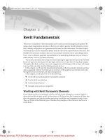
Figure 7.1 shows a hand sketch using very gestural lines, tones, and hatches. The ability to sketch
freely and with gestural expression is a fundamental aspect of design iteration and has been part
of the architectural profession for centuries.-
Figure 7.1
An inspiring
early sketch
Images courtesy of Emmanuel Di Giacomo
44831.book Page 201 Friday, October 12, 2007 12:31 AM
Please purchase PDF Split-Merge on www.verypdf.com to remove this watermark.
202
CHAPTER 7
CONCEPT MASSING STUDIES
Architects have long realized that the only way to make an investor buy in into their early ideas
and designs is to make that investor understand the designs. Many investors have difficulty read-
ing technical drawings, so architects use creative methods to communicate the design, the space,
and the experience of that space. Perspective drawings, photo collages, and 3D physical models
made of wood, Styrofoam, cardboard, balsa, Plexiglas, and metals are all used to help the client,
and sometimes the public, understand the implications of a given design.
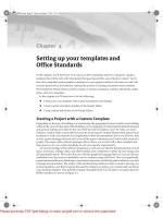
In more sophisticated building studios, these models are constructed so that the design can be
evaluated by deconstructing the model to examine individual stages of construction and integrated
systems. Models can range in fidelity from very rough massing studies to highly photorealistic ren-
derings, as Figure 7.2 demonstrates.
Figure 7.2
Models can range
from very rough
(a and b) to highly
refined representa-
tions (c and d).
3D physical models offer some obvious advantages for conveying design intent:
◆
You get an immediate feel for proportion, scale, and composition.
◆
You can get a feel for spatial volume.
◆
Light and shadow can be easily simulated.
◆
It’s possible to model the surrounding site and understand how your design relates to its
context.
3D physical models also have some potential disadvantages:
◆
They take a lot of time and patience to create.
◆
They require space for creation as well as storage.
◆
They are created in only one scale.
◆
They can’t handle design options easily.
ab
cd
Image courtesy of BNIM Architects
44831.book Page 202 Friday, October 12, 2007 12:31 AM
Please purchase PDF Split-Merge on www.verypdf.com to remove this watermark.
MASSING STUDIES
203
◆
They require manual work—both in the physical modeling and in performing calculations
of area and space.
◆
They can be costly in terms of skilled personnel, materials, and equipment.
As clients become more demanding, they aren’t satisfied with understanding how the future
building will look, but also want to know how the building will perform in terms of lifecycle costs.
They need the ability to compare and contrast multiple solutions in order to arrive with you at an
optimized design solution that meets their taste, all the program requirements, and is sustainable
economically.
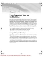
To accommodate all that, architects and owners need to analyze the building and experience it
in the early stages of design before it’s built. Traditional hand-built models don’t provide this kind
of analytical flexibility. This is where using digital models backed up by real data comes into play.
See Figure 7.3.
Figure 7.3
Early massing studies
Massing Study Workflows
Regardless of how a massing study is done (digitally or in a physical medium), there has always
been a break in the workflow from conceptual design to finished building. Physical massing models
were made first and then, to create a digital project, the architect had to re-create the same concept
from zero, usually in AutoCAD without having a way to reuse the information previously created.
When you make a digital study using tools such as Rhino, SketchUp, Form Z, or 3ds Max, you
still need to start from scratch to begin the process of documenting your design because they are
just modelers, not documentation tools, and the data created in them is not reusable in any intelli-
gent way.
Image courtesy of Gianluca N. Lange
44831.book Page 203 Friday, October 12, 2007 12:31 AM
Please purchase PDF Split-Merge on www.verypdf.com to remove this watermark.
204
CHAPTER 7
CONCEPT MASSING STUDIES
This has traditionally occurred in the form of 2D drawings using a tool such as AutoCAD. With
the advent of Building Information Modeling, this is all changing.
An important part of using BIM is being able to use data throughout the design process, from
start to finish—without needing to start over from ground zero once you’ve got the massing done.
Revit provides specific tools for keeping the design process integrated. For early conceptual stud-
ies, Revit has massing tools that allow you to create a mass model that can later easily be trans-
formed into walls, floors, and roofs. This capability is popularly called Building Maker, a set of
tools for converting an abstract mass form into a full-fledged building model.
With the massing tools, you can create flexible preliminary designs and create massing models
out of building blocks long before you make decisions about walls, roofs, and floors. You can create
the pieces quickly, run though and visualize alternate configurations, and then, only when they’re
ready, generate a building shell.
Common Uses for the Massing Tools
Here are some commons scenarios where using Revit massing tools make sense.
Site Studies: Using Massing to Quickly Build the Context Environment
Around the Building
You can use massing capabilities to quickly model the surrounding context of your building to get a feel
for how it fits. This is a standard practice used to demonstrate to clients or for competitions how your
design relates to its environment. Once you have modeled the environment around your building, you
can make quick walkthroughs around your building and experience it from different points of view
from various vantage points. You can also make initial solar studies to better understand how your
building affects the environment and how the environment affects your design.
Image courtesy of Kubik-Nemeth-Vlkovic
44831.book Page 204 Friday, October 12, 2007 12:31 AM
Please purchase PDF Split-Merge on www.verypdf.com to remove this watermark.
MASSING STUDIES
205
Massing Studies for Testing Different Design Options
You can do a quick conceptual massing study to work out a functional design arrangement, make more
options, and look for an optimal solution. For each design, separate masses can be made and given color
to indicate their form. This allows you to see spatial relationships in simplified geometric forms but also
get precise area and volume values for each mass option you explore.
Feasibility Studies and Program Verification
You can take the massing study a step further and make a feasibility study, explore how you can fit the
client’s program on the site, calculate the Floor Area Ratio (FAR), and convert it into a building with
walls, floor, roofs, and site elements. With mode information added to the model, you can get better
estimates about building cost, energy analysis, and aesthetics.
Image Courtesy of Gensler
Image courtesy of RMJM Hillier, Design Competition,
Master Plan Massing Study
44831.book Page 205 Friday, October 12, 2007 12:31 AM
Please purchase PDF Split-Merge on www.verypdf.com to remove this watermark.
206
CHAPTER 7
CONCEPT MASSING STUDIES
Massing Tools
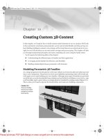
The massing tools are located on the Design bar’s Massing tab (Figure 7.4). If you don’t see it, acti-
vate it by right-clicking anywhere on the Design bar and clicking Massing. To create a massing
study, analyze it, and convert it to a building, you need to understand the available tools first; then,
we’ll walk through a real exercise.
Figure 7.4
The Massing tab
provides all the tools
needed to create a
massing study.
Image courtesy of Gensler
Mass-creation tools
Building Maker tools
View tools
44831.book Page 206 Friday, October 12, 2007 12:31 AM
Please purchase PDF Split-Merge on www.verypdf.com to remove this watermark.
MASSING STUDIES
207
The tools for creating masses in Revit are directly connected to the modeling tools and tech-
niques we discussed in Chapter 6. You’ll use the same modeling tools (Extrusion, Blend, Sweep,
Revolve) as well as the logic of work planes and placing by face whenever you create a mass,
whether in the project environment or the Family Editor.
The Massing design bar is divided into three groups of tools that we refer to as mass-creation
tools, Building Maker tools, and view tools.
The first group allows you to make masses from scratch or place massing families. The second
group contains tools to support the concept of
Building Maker
—a term that doesn’t exist in the Revit
UI but is commonly adopted among Revit users to describe the process of converting a concept
massing into a real building. Using the faces of a conceptual mass, you can attach walls, curtain sys-
tems, floors, and roofs to the mass form with a click of the mouse. Later in this chapter we’ll refer
to this grouping as
Building Maker
.
The third group contains the standard Section and Level tools; these are the most important
additional tools to have at hand during creation of mass studies. They are the same Section and
Level tools that you find on the Basic menu or in the views.
Creating a Massing Element
There are two ways to create a mass element in the project environment:
Select the Create Mass tool
This method allows you to create a new mass element.
Select the Place Mass tool
This method allows you to place a massing family or load a mass
family from your library.
Before we look in detail at these two methods, you need to understand how massing visibility
is handled in Revit, because you’ll encounter this issue the moment you start creating masses.
Visibility of Masses
When you try to place mass or create mass for the first time, you may get the following message,
which conveys information about the visibility of the mass elements:
This message can be disconcerting at first, so let’s understand what is going on. Visibility of
mass elements can be controlled via the toolbar or as a category in the Visibility/Graphic Overrides
dialog. The toolbar control is a global on/off switch for massing that affects all views temporarily.
It’s located at the top of the screen, near the 3D button:
44831.book Page 207 Friday, October 12, 2007 12:31 AM
Please purchase PDF Split-Merge on www.verypdf.com to remove this watermark.
208
CHAPTER 7
CONCEPT MASSING STUDIES
When you select this button, all masses in all views become visible. This is great for early mass-
ing studies, allowing you to move from view to view and see your mass without having to turn the
category on/off for each view. When this mode is enabled, it
does not
affect the Visibility/Graphics
Overrides state of your views.
To see the mass elements in specific views only, you should use the Visibility/Graphics Over-
rides settings for view control. Even when the Show Mass button is turned off, if you check the
Mass setting in the Visibility/Graphic Overrides dialog, it will be visible in that view.
To print and export massing, you need to turn the mass category on using the Visibility/Graphic
Overrides dialog. The Massing toggle is a temporary view control and doesn’t affect printed output.
As you develop your design further and start creating the real building components (walls,
floors, and roofs) by adding elements to the model, the mass will become obscured. A great way to
maintain a view where only massing is visible is to create a 3D view where
all categories are turned
off except massing
. Name the view Massing or something appropriate. Figure 7.5 shows two views:
one with only the massing category visible and the other with all categories visible. This is handy,
for example, when you want to make adjustments to the basic shapes that define the geometry
(masses) without being distracted by the presence of the building elements. When you change the
underlying mass, the architectural elements created from it follow the change automatically. You’ll
learn more about this workflow in Chapter 8.
Figure 7.5
The same view with
different visibility
states for massing and
model elements
Masses in Revit appear with transparent materials in 3D views by default. When you switch to
floor plan, however, they appear solid. Users of Revit have shared this experience and some sug-
gest orienting a 3D view to a floor-level plan. You’ll notice the difference with the behavior of the
shadows as well: Although a floor-plan view of a mass displays a shadow, an oriented 3D view
doesn’t.
Starting a Conceptual Massing Study
You can create massing forms using Revit’s 3D modeling tools. Use these tools to quickly generate
site plans and initial building shapes in the early phase of design development.
Creating a Mass
In the Massing Design Tab, when you select Create Mass, you’re first prompted to name the mass
you’re about to create. Once you provide a name, the interface transforms into mass-creation mode,
View with only the massing category visible View with all categories visible
44831.book Page 208 Friday, October 12, 2007 12:31 AM
Please purchase PDF Split-Merge on www.verypdf.com to remove this watermark.
MASSING STUDIES
209
with a new set of tools on the Design bar (Figure 7.6). Using these tools, you proceed to create the
massing form using combinations of solid and void forms.
Figure 7.6
The Design bar for
massing creation
This creation mode is similar to that of the Family Editor, where a select set of tools are presented
that are relevant to parametric creation of forms. You’ll also notice some overlap with the Create
tool in the Modeling Design bar. The underlying principles in all these environments (Family
Editor, in-place Family Editor, and Massing Editor) are the same.
Most tools on this Design bar should be familiar. The only unique feature is the Place Mass tool.
When selected, this tool does the same thing as the Place Mass tool on the Massing Design tab: It
lets you place a mass family. This is a component-placement tool that only places components of
the mass category.
When you’re in mass-edit mode, you can create mass elements that are represented by a single
shape or are a combination of shapes, solids, and voids. Everything you add is considered part of
the mass you’re creating. You can place as many different masses in this mode as you require. Your
decision whether to make each shape a separate mass will depend on what you need it to represent
and how you intend to interact with it. For example, one mass element could have five extrusions
representing five buildings. Or, you could make five separate mass elements for each building. Do
you want to move each building independently? Or will you likely want to move all the buildings
together, as one element?
When you’ve finished modeling the mass, you click Finish Mass, and everything you modeled
becomes one mass element. To edit a mass, select it and click the Edit button on the Options bar.
Be aware that a mass element must have solid geometry in it—it can’t be made of voids alone.
If you try to make a void massing, you’ll get a warning message like the one shown in Figure 7.7.
Figure 7.7
Error message for a
mass without solids
It’s possible to get the same message even if you do have a solid but the void isn’t cutting
through the solid.
For example, if you draw the solid first and then the void, the message won’t appear. If you do
the opposite and add the void before the solid, you’ll get the message. To solve this problem, you
need to use the Cut Geometry tool to make the solids and voids intersect. Only by using this tool
will this message be cleared so you can finish the mass. Figures 7.8 and 7.9 show this.
44831.book Page 209 Friday, October 12, 2007 12:31 AM
Please purchase PDF Split-Merge on www.verypdf.com to remove this watermark.
210
CHAPTER 7
CONCEPT MASSING STUDIES
Figure 7.8
If you draw a void be-
fore you add a solid,
they won’t intersect or
have any relation-
ship—the mass can’t
be completed in
this case.
Figure 7.9
Adding a void after
placing a solid cuts it
from the solid. The
mass can then be
completed.
The Cut and Join Geometry tools are both available on the Options bar when forms are selected.
These tools are important when you’re dealing with massing, so let’s look more closely at them:
Cut Geometry
This tool cuts voids out of solids. You select the tool, select a void, and then
select what you want the void to cut. Voids can cut multiple solids.
Join Geometry
This tool joins solids (voids can’t be joined together) to form one connected ele-
ment. It merges the shapes (masses) into one, both graphically and as data (Figure 7.10). To use
this tool, select the tool, and then select solids you want to join. Multiple solids can be joined
together.
If you change the position of one of the joined masses, the intersection (called the
joining
)
instantly updates. However, if you move one of the joined masses outside the boundaries of the
other joined masses so they don’t intersect any more, you’ll get a warning message. To resolve the
problem, you can use the Unjoin Geometry command. Note that even if the mass elements are
joined, selecting the mass results in the selection of just one of them (Figure 7.11).
Solid Void
44831.book Page 210 Friday, October 12, 2007 12:31 AM
Please purchase PDF Split-Merge on www.verypdf.com to remove this watermark.