Báo cáo hóa học: " Mass spectrometry based on a coupled Cooperpair box and nanomechanical resonator system" pdf
Bạn đang xem bản rút gọn của tài liệu. Xem và tải ngay bản đầy đủ của tài liệu tại đây (728.94 KB, 8 trang )
NANO EXPRESS Open Access
Mass spectrometry based on a coupled Cooper-
pair box and nanomechanical resonator system
Cheng Jiang, Bin Chen, Jin-Jin Li and Ka-Di Zhu
*
Abstract
Nanomechanical resonators (NRs) with very high frequency have a great potential for mass sensing with
unprecedented sensitivity. In this study, we propose a scheme for mass sensing based on the NR capacitively
coupled to a Cooper-pair box (CPB) driven by two microwave currents. The accreted mass landing on the
resonator can be measured conveniently by tracking the resonance frequency shifts because of mass changes in
the signal absorption spectrum. We demonstrate that frequency shifts induced by adsorption of ten 1587 bp DNA
molecules can be well resolved in the absorption spectrum. Integration with the CPB enables capacitive readout of
the mechanical resonance directly on the chip.
1 Introduction
Nanoelectromechanical systems (NEMS) offer new pro-
spects for a variety of important applications ranging
from semiconductor-based technology to fundamental
science [1]. In particular, the minuscule masses of
NEMS resonators, combined with their high frequencies
and high resonanc e quality factors, are very appe aling
for mass sensing [2-7]. These NEMS-based mass sensing
employs t racking the resonance frequency shifts of the
resonators due to mass changes. The mo st frequently
used techniques for measuring the resonance freque ncy
are based on optical detection [8]. Though inherently
simple and highly sensitive, this technique is susceptible
to temperature fluctuation noise because it usually gen-
erates heat and heat conduction. On the other hand, it
has experimentally been demonstrated that capacitive
detection is less affected to noise than optical detection
in ambient atmosphere [9]. Capacitive detection is rea-
lized by connecting NEMS resonator with standard
microelectronics, such as complementary metal-oxide-
semiconductor (CMOS) circuitry [10]. Here, we propose
a scheme for ma ss sensing based on a coup led nanome-
chanical resonator (NR)-Cooper-pair box (CPB) system.
The basic superconducting CPB consists of a low-
capacitance superconducting electrode weakly linked to
a superconducting reservoir by a Josephson tunnel
junction. Owing to its controllabi lity [11-14], a CPB has
bee n proposed to couple to th e NR to drive an NR into
a superposition of spatially separated states and probe
the decay of the NR [15], to prepare the NR in a Fock
state and perform a quantum non-demolition measure-
ment of t he Fock s tate [16], and to cool the NR to its
ground state [17]. Recently, this coupled CPB-NR sys-
tem has been realized in experimen ts [18,19] and the
resonance frequency shifts of the NR could be moni-
tored by performing microwave (MW) spectroscopy
measurement. Based on the a bove-mentione d achieve-
ments, in this article, we investigate the signal absorp-
tion spectrum of the CPB qubit capacitively coupled to
an NR in the simultaneous presence of a stron g control
MW current and a weak signal MW current. Theoreti-
cal analysis shows that two sideband peaks appear at the
signal absorption spectrum, which exactly correspond to
the resonance frequency of the NR. Therefore, the
accreted mass landing on the NR can b e weighed pre-
cisely by measuring the frequency shifts because of mass
changes of the NR in the sig nal absorption spectrum.
Similar mass sensing scheme has been proposed recently
in a hybrid nanocrystal coupled to an NR by our group
[20], which is based on a theoretical model. However,
recent experimental achievements in the coupled CPB-
NR system [18,19] make it possible for our proposed
mass sensing scheme here to be realized in future.
* Correspondence:
Key Laboratory of Artificial Structures and Quantum Control (MOE),
Department of Physics, Shanghai Jiao Tong University, 800 Dong Chuan
Road, Shanghai 200240, China
Jiang et al. Nanoscale Research Letters 2011, 6:570
/>© 2011 Jiang et al; l icensee Springer. This is an Open Access article d istributed under the terms of the Creative Commons Attrib ution
License ( which permi ts unrestricted use, distribution, and reproduction in any medium,
provided the original work is properly cited.
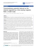
2 Model and theory
In our CPB-NR composite system shown schematically
inFigure1,theNRiscapacitivelycoupledtoaCPB
qubit consisting of two Josephson junctions which form
a SQUID loop. A strong control MW current and a
weak signal MW current are simultaneously applied in a
MW line through the CPB to induce the oscillating
magnetic fields in the Josephson junction SQUID loop
of the CPB qubit. Besides, a direct current I
b
is also
applied to the MW line to control the magnetic flux
through the SQUID loop and thus the effective Joseph-
son coupling of the CPB qubit. The Hamiltonian of our
coupled CPB-NR system reads:
H = H
C
PB
+ H
NR
+ H
in
t
,
(1)
H
CPB
=
1
2
¯
hω
q
σ
z
−
1
2
E
J0
cos
πΦ
x
(t )
Φ
0
σ
x
,
(2)
H
NR
=
¯
hω
n
a
†
a
,
(3)
H
int
=
¯
hλ
(
a
†
+ a
)
σ
z
.
(4)
where H
CPB
is the Hamiltonian of the CPB qubit
described by the pseudospin -1/2 operators s
z
and s
x
= s
+
+ s
-
. ω
q
=4E
c
(2n
g
-1)/ħ is the electrostatic energy dif-
ference and E
J0
is the maximum Josephson energy. Here,
E
C
= e
2
/2C
Σ
is the charging energy wit h C
Σ
= C
b
+ C
g
+
2C
J
being the CPB island’ s total capacitance a nd n
g
=
(C
b
V
b
+ C
g
V
g
)/(2e) is the dimensionless polarization
charge (in units of Cooper pairs), where C
b
and V
b
are,
respectively, the capacitance and voltage between the NR
and the CPB island, C
g
and V
g
are, respectively, the gate
capacitance and vol tage o f th e CPB qubit, a nd C
J
is the
capacitance of each Josephson junction. Displacement
(by x) of the NR leads to linear modulation of the capaci-
tance between NR and CPB, C
b
(x) ≈ C
b
(0) + (∂C
b
/∂x)x ,
which modulates the electrostatic energy of the CPB
qubit, resulting in the capacitive coupling constant
λ =
4n
NR
g
E
C
¯
h
1
C
b
∂C
b
∂x
x
z
p
,where
n
N
R
g
= C
b
V
b
/2
e
and
x
z
p
=
¯
h/2mω
n
is the zero-point uncertainty of the NR
with effective mass m and resonance frequency ω
n
.The
coupling between the MW line and the CPB qubit in the
second term of Equation 2 results from the totally ext er-
nally applied magnetic flux F
x
( t)=F
q
(t)+F
b
through
the CPB qubit loop of an effective area S with F
0
= h/(2e)
being the flux quantum. Here, F
q
(t)=μ
0
SI(t )/(2πr), with
r being the distance between the MW line and the qubit
and μ
0
being the vacuum permeability. F
q
(t)andF
b
are
controlled, respectively, by the MW current
I
(
t
)
= E
c
cos
(
ω
c
t
)
+ E
s
cos
(
ω
s
t + δ
)
and the direct curre nt
I
b
in the MW line. For convenience, we assume the phase
factor δ’ = 0 because it is not difficult to demonstrate that
the results of this article are not dependent on the value
of δ’. By adjusting the direct current I
b
and the MW cur-
rent I(t) such that F
b
≫ F
q
( t)andπF
b
/F
0
= π /2, we
can obtain
E
J
cos
πΦ
x
(t)
Φ
0
≈−E
J
πΦ
q
(t)
Φ
0
.
In a rotating
Figure 1 Schematic diagram of an NR capacitively coupled to a CPB. Two MW currents with frequency ω
c
and ω
s
and a direct current I
b
are applied in the MW line to control the magnetic flux F
x
through the CPB loop.
Jiang et al. Nanoscale Research Letters 2011, 6:570
/>Page 2 of 8
frame at the control frequency ω
c
, the total Hamiltonian
can now be written as
H =
1
2
¯
hσ
z
+
¯
hω
n
a
†
a +
¯
hλ(a
†
+ a)σ
z
+
¯
h(σ
+
+ σ
−
)
+μ
E
s
(σ
+
e
−iδt
+ σ
−
e
iδt
),
(5)
where Δ = ω
q
- ω
c
is the detuning of the qubit reso-
nance frequency and the control current frequency, δ =
ω
s
- ω
c
is the detuning of the si gnal current and the
control current, μ = μ
0
SE
J0
/(8rF
0
)istheeffective‘elec-
tric dip ole moment’ of the qubit, and
Ω = μE
c
/
¯
h
is the
effective ‘Rabi frequency’ of the control current.
The dynamics of the coupled CPB-NR system in the
presence of dissipation and dephasing is described b y
the following master equation [21]
dρ
dt
= −
i
¯
h
[H, ρ]+
1
2T
1
L[σ
−
]+
γ
2
L[a]+
1
4τ
φ
L[σ
z
]
,
(6)
where r is the density matrix of the coupled system,
T
1
is the qubit relaxation time, τ
j
is the qubit pure
dephasing time, and g is the decay ra te of the NR which
is given by g = ω
n
/Q.
L[
D
]
, describing the incoherent
decays, is the Lindblad operator for an operator and is
given by:
L
[
D
]
=2DρD
†
− D
†
Dρ − ρD
†
D
.
(7)
Using the identity
˙
O = Tr
(
O ˙ρ
)
for an operator O and
a density matrix r in Equation 6, we obtain the follow-
ing Bloch equations for the coupled CPB-NR system:
dσ
−
dt
= −
1
T
2
+ i
σ
−
−i Qσ
−
+ iΩσ
z
+
i
¯
h
μ
E
s
σ
z
e
−iδt
,
(8)
dσ
z
dt
= −
1
T
1
(σ
z
+1)− 2iΩ(σ
+
−σ
−
)
−2
i
¯
h
μ(
E
s
σ
+
e
−iδt
− E
∗
s
σ
−
e
iδt
),
(9)
d
2
Q
dt
2
+ γ
dQ
dt
+ ω
2
r
Q = −4ω
3
r
λ
0
σ
z
,
(10)
where
λ
0
=
λ
2
ω
2
n
and T
2
is the qubit dephasing time
satisfying
1
T
2
=
1
2T
1
+
1
τ
φ
.
(11)
Note that if the pure dephasing rate is neglected, i.e.,
1
τ
φ
=
0
,thenT
2
=2T
1
. In order to solve the above
equations, we first take the semiclassical approach by
factorizing the NR and CPB qubit degrees of freedom, i.
e., 〈Q s
-
〉 = 〈Q〉〈s
-
〉, which ignores any entanglement
between these systems. For simplicity, we define p = μs
-
, k = s
z
and then we have
dp
dt
=
−
1
T
2
− i( + Q)
p + i
μ
2
kE
¯
h
,
(12)
dk
dt
= −
1
T
1
(k +1)−
4
¯
h
Im(p
E
∗
)
,
(13)
d
2
Q
dt
2
+ γ
dQ
dt
+ ω
2
r
Q = −4λ
0
ω
3
r
k
(14)
where
E = E
c
+ E
s
e
−iδ
t
.Inordertosolvetheabove
equations, we make the a nsatz 〈p(t)〉 = p
0
+ p
1
e
-iδt
+ p
-
1
e
iδt
, 〈k(t)〉 = k
0
+ k
1
e
-iδt
+ k
-1
e
iδt
, and 〈Q(t)〉 = Q
0
+ Q
1
e
-
iδt
+ Q
-1
e
iδt
[22]. Upon substi tuting these equations into
Equations 12-14 and upon working to the lowest order
in
E
s
but to all orders in
E
c
, we obtain in the steady
state:
p
1
=
μ
2
E
s
T
2
k
0
¯
h
2T
1
/T
2
B(δ
0
+2i)(C + Ω
2
c
)+E(B − δ
0
)
AE(B − δ
0
)
.
(15)
where
A =
c
− 4λ
0
ω
0
k
0
− δ
0
− i,
B =
c
− 4λ
0
ω
0
k
0
+ δ
0
+ i,
C =4λ
0
ω
0
k
0
ηΩ
2
c
/(
c
− 4λ
0
ω
0
k
0
− i),
D =4λ
0
ω
0
k
0
ηΩ
2
c
/(
c
− 4λ
0
ω
0
k
0
+ i),
E =2T
1
/T
2
A(D + Ω
2
c
) − 2T
1
/T
2
B(C + Ω
2
c
)
− AB(T
1
/T
2
δ
0
+ i).
(16)
Here, dimensionless variables ω
0
= ω
r
T
2
, g
0
= gT
2
, Ω
c
= ΔT
2
,andΔ
c
= ΔT
2
are introduced for convenience
and the auxiliary function
η =
ω
2
0
ω
2
0
− iγ
0
δ
0
− δ
2
0
.
(17)
The population i nversi on k
0
of the CPB is determined
by
(k
0
+1)[(
c
− 4λ
0
ω
0
k
0
)
2
+1]+4Ω
2
c
k
0
T
1
T
2
=0.
(18)
p
1
is a parameter corresponding to the linear suscept-
ibility
χ
(
1
)
(
ω
s
)
= p
1
/E
s
=
(
μ
2
T
2
/
¯
h
)
χ
(
ω
s
)
,wherethe
dimensionless linear susceptibility c(ω
s
) is given by
χ(ω
s
)=
2T
1
/T
2
B(δ
0
+2i)(C + Ω
2
c
)+E(B − δ
0
)
AE(B − δ
0
)
k
0
.
(19)
Jiang et al. Nanoscale Research Letters 2011, 6:570
/>Page 3 of 8
The real and imaginary parts of c(ω
s
) characterize,
respectively, the dispersive and absorptive properties.
The coupled CPB-NR system has been proposed to
measure the vibration frequency of the NR by calc ulat-
ing the absorption spectrum [23]. On the other hand,
NRs have widely been used as mass sensors by measur-
ing the resonant frequency shift because of the added
mass of the bound particles. The mass sensing principle
is simple. NRs can be described by harmonic oscillators
with an effective mass m
eff
, a spring constant k,anda
mechanical resonance frequency
ω
n
=
k/m
ef
f
.Whena
particle adsorbs to the resonator and significantly
increases the resonator ’seffectivemass,therefore,the
mechanical resonance f requ ency reduces. Mass sensing
is based on monitoring the frequency shift Δω of ω
n
induced by the adsorption to the resonator. The rela-
tionship between Δ ω with the deposited mass Δm is
given by
m = −
2m
eff
ω
n
ω = R
−1
ω
,
(20)
where
R =
(
−2m
eff
/ω
n
)
−
1
is defined as the mass
responsivity. However, the measurement techniques are
rather challenging. For example, electrical measurement
is unsuitable for mass detections based on very high fre-
quency NRs because of the generated heat ef fect [24].
For optical det ection, as device dimensions are scaled
far below the detection wavelength, diffraction effects
become pronounced and will limit the s ensitivity of this
approach [25]. Moreover, in any actual implementation,
frequency stability of the measuring system as well as
various noise sources, including thermomechanical noise
generated by the internal loss mechanisms in the reso-
nator and Nyquist-Johnson noise from the readout cir-
cuitry [3,26] will also impose limits to the sensitivity of
measurement. Here, we can determine the frequency
shifts with high precision by the MW spectroscopy mea-
surement based on our coupled CPB-NR system.
3 Numerical results and discussion
In what follows, we choose the realistically reasonable
parameters to demonstrate the validity of mass sensing
based on the coupled CPB-NR system. Typical para-
meters of the CPB (charge qubit) are E
C
/ħ =40GHz
and E
J0
/ħ = 4 GHz su ch that E
C
≫ E
J
[27]. Experiments
by many researchers have demonstrated CPB eigenstates
with excited state lifetime of up to 2 μs and coherence
times of a supe rpositions states as long as 0.5 μs, i.e., T
1
=2μs, and T
2
=0.5μs [13,28,29]. NR with resonance
frequency ω
n
=2π × 133 MHz, quality factor Q = 5000,
and effective mass m
eff
= 73 fg has been used for zepto-
gram-scale mass sensing [5]. Besides, coupling constant
l b etween the CPB and NR can be chosen as l =0.1ω
n
=2π × 13.3 MHz [16]. We assume S =1μm
2
, r =10
μm, and
E
c
=200
μA
[30], therefore, we can obtain μ/ħ =
μ
0
SE
J0
/(8ħrj
0
) ≈ 30 GHzA
-1
and
Ω
c
= ΩT
2
=(μ/
¯
h)E
c
T
2
=3
.Theexperimentsofour
proposed mass sensing scheme should be done in situ
within a cryogenically cooled, ultrahigh v acuum appara-
tus with base pressure below 10
-10
Torr.
Firstly, we would show the principle of measuring the
resonance frequency of the NR in the coupled CPB-NR
system. Figure 2a illustrates the absorption of the signal
current as a function of the detuning Δ
s
(Δ
s
= ω
s
- ω
q
).
The absorption (Im(c)) has been normalized with its
maximum when the control current is resonant with the
CPB qubit (Δ
c
= 0). Mollow triplet, commonly known in
atomic and some artificial two-level system [31,32],
appears in the middle part of Figure 2a. However, there
are also two sharp peaks located exactly at Δ
s
=±ω
n
in
the sidebands of the absorption spectrum, which corre-
sponds to the resonant absorption and amplification of
the vibrational mode of the NR. Our proposed m ass
sensing scheme is just based on these n ew features in
the absorption spectrum. An intuitive physical picture
explaining these peaks can be given in the energy level
diagram shown in Figure 2b. The Hamiltonian of the
coupled system without the externally applied current
can be diagonalized [33,34] in the eigenbasis of
|
±, N
±
=
|
±
z
⊗ e
∓(λ/ω
n
)(a
†
−a)
|
N
,withtheeigenener-
gies E
±
=±ħ/2ω
q
+ ħω
n
(N - l
0
), where the CPB qubit
states |±〉
z
are eigenstates of s
z
with the excited state |+〉
z
=|e〉 and the ground state |-〉
z
=|g〉,theresonator
states |N
±
〉 are position-displaced Fock states. Transi-
tions betwe en |-, N
-
〉 and |+, (N +1)
+
〉 represent signal
abso rption centered at ω
c
+ ω
n
(the rightmost solid line
in Figure 2b). Besides, transitions between |+, N
+
〉 and
|-, (N +1)
-
〉 indicate probe amplification (the left most
solid l ine in Figure 2b) because of a three-photon pro-
cess, involving simultaneous absorption of two control
photons and emission of a photon at frequency ω
c
- ω
n
.
The middle dashed lines in Figure 2a corresponds to the
transition where the signal frequency is equal to the
control frequency. Therefore, Figure 2a provides a
method to measure the resonance f requency of t he NR.
If we first tune the frequency of the control MW cur-
rent to be resonant with the CPB qubit (ω
c
= ω
q
)and
scan the signal frequency across the CPB qubit fre-
quency, then we can easily obtain the resonance fre-
quency of the NR from the signal absorption spectrum.
Next, we illustrate how to measure the mass of the
particles landing on the NR based on the above discus-
sions. Unlike traditional mass spectrometers, nanome-
chanical mass sensors do not require the potentially
destructive ionization of the test sample, are more sensi-
tive to large biomolecules, such as proteins and DNA,
Jiang et al. Nanoscale Research Letters 2011, 6:570
/>Page 4 of 8
and could eventually be incorporated on a chip [6].
Here, we use the functionalized 1587 bp long dsDNA
molecules with mass m
DNA
≈ 1659 zg (1 zg = 10
-21
g)
[35], and assume for simplicity that the mass adds uni-
formly to the mass of the overall NR and changes the
resonance frequency of the NR by an amount given by
Equation 19. Figure 2c demonstrates the signal absorp-
tion as a function of Δ
s
before and after a binding event
of ~ 10 functionalized 1587 bp DNA molecules i n the
vicinity of the resonance frequency of the NR. We can
see clearly that there is a reson ance frequency shift Δω
= -95 kHz after the adsorption of the DNA molecules
because of the increased mass of the NR. According to
Equation 19, we can obtain the mass of the accreted
DNA molecule:
m = −
2m
eff
ω
n
ω = 16590z
g
, about the
mass of 10 functionalized 1587 bp long dsDNA m ole-
cules. Therefore, such a coupled CPB-NR system can be
used to weigh the external accr eted mass landing on the
NR by measuring the frequency shift in the signal
absorption spectrum when the control current is reso-
nant with the CPB qubit. Plot of frequency shifts versu s
the number of DNA molecules landing on two different
masses of NRs. Other parameters used a re ω
n
=835
MHz, l
0
=0.01,Δ
c
=0,Q = 5000, T
1
=0.25μs, T
2
=
0.05 μs, and Ω
c
= 3. Mass responsivity
R
is an impor-
tant parameter to evaluate the performance of a resona-
tor for mass sensing. Figure 3 plots the frequency shifts
as a function of the number of DNA molecules landing
on t he NR for two different kinds of NRs. One is ω
n
=
2π ×133MHz(m
eff
= 73 fg), the other is ω
n
=2π ×
190 M Hz (m
eff
= 96 fg) [2,3]. The mass responsivities,
which can be obtained from the slope of the line, are,
respectively,
|R|≈5.72 Hz
/
z
g
and
|
R|≈6.21 Hz
/
z
g
.
Smaller mass of the nanoresonator enables higher mass
Figure 2 Scaled absorption spectrum of the signal current as a function of the detuning Δ
s
and energy level diagram of the coupled
system. (a) Scaled absorption spectrum of the signal current as a function of the detuning Δ
s
without landing any masses on the NR. (b) The
energy level diagram of the CPB coupled to an NR. (c) Signal absorption spectrum as a function of Δ
s
before (black solid line) and after (red
dashed line) a binding event of ~ 10 functionalized 1587 bp long dsDNA molecules. Frequency shift of 95 kHz can be well resolved in the
spectrum. Other parameters used are ω
n
= 835 MHz, l
0
= 0.01, Δ
c
=0,Q = 5000, T
1
= 0.25 μs, T
2
= 0.05 μs, and Ω
c
=3.
Jiang et al. Nanoscale Research Letters 2011, 6:570
/>Page 5 of 8
responsivity. Here, we have assumed that the DNA
molecules land evenly on the NR and they remain on it.
In fact, the position on the surface of the resonator
where the binding takes place is one factor that strongly
affects the resonance frequency shift. The maximization
in mass responsivity is obtained if the landing takes
places at the position where the resonator’svibrational
amplitudeismaximum.ForthedoublyclampedNR
used in our model, maximum shift is achieved at the
center for the fundamental mode of vibration, while the
minimum shift exists at the clamping points. This statis-
tical distribution of frequency shifts has been investi-
gated by building the histogram of event probability
ver sus frequency shift for small ensembles of sequential
singl e molecule or single nanoparticle adsorpti on events
[6,7].
In order to demonstrate the novelty of our proposed
mass sensing scheme, we plot Figure 4 to illustrate how
the vibration mode of NR and the control current affect
the spectral features. Figure 4a shows the absorption
spectrum of the signal field through the CPB system
without the influence of the NR (coupling off) in the
absence of the control field (control off), which shows
the standard resonance absorption profile. However,
when the coupling turns on, the center of the curve
shifts from the r esonance ω
s
= ω
q
a bit, as shown in
Figure 4b. This is because of the coupling l
0
between
the CPB and the NR [16,36]. Figure 4c demonstrates the
absorption spectrum of the signal field when the control
field turns on in the absence of the NR (coupling off).
This is the commonly known Mo llow triplet, which
appears in atomic and some artificial two-level system
[31,32]. None of the above situations can be used to
measure the resonance frequency of the NR. However,
when the coupled CPB-NR system is driven by a strong
control fiel d and a weak signal field simultaneously, the
resonance frequency of the NR be measured from the
absorption spectrum of the signal field, as shown in Fig-
ure 4d. The spectral linewidth of the two sideband
peaks that c orresponds to the resonance frequency of
the NR is much narrower than the peak in the center,
since the damping rate of the NR is much smaller than
the decay rate of the CPB qubit. Therefore, such a
coupled CPB-NR system is proposed here to measure
Figure 3 Plot of frequency shifts versus the number of DNA molecules landing on two different masses of NRs. Other parameters used
are ω
n
= 835 MHz, l
0
= 0.01, Δ
c
=0.Q = 5000, T
1
= 0.25 μs, T
2
= 0.05 μs, and Ω
c
=3.
Jiang et al. Nanoscale Research Letters 2011, 6:570
/>Page 6 of 8
the resonance frequency of the NR when the control
field i s resonant with the CPB qubit (ω
c
= ω
q
). By mea-
suring the frequency shift of the NR before and after
the adsorption of particles landing on it, we can obtain
the accreted mass according to Equation 19.
4 Conclusion
To conclude, we have demonstrated that the coupled
NR-CPB system driven by two MW currents can be
employed as a mass sensor. In this coupled system, the
CPB serves as an auxiliary system to read out the reso-
nance frequency of the NR. Therefore, the accreted
mass landing on the NR can be weighed conveniently
by measuring the frequency shifts in the signal absorp-
tion spectrum. In addition, the use of on-chip capacitive
readout will prove especially advantageous for detection
in liquid environments of low or arbitrarily varying opti-
cal transparency, as well as for operation at cryogenic
temperatures, where maintenance of precise optical
component alignment becomes difficult.
Acknowledgements
The authors gratefully acknowledge the support from the National Natural
Science Foundation of China (Nos. 10774101 and 10974133) and the
National Ministry of Education Program for Training Ph.D.
Authors’ contributions
CJ finished the main work of this article, including deducing the formulas,
plotting the figures, and drafting the manuscript. BC and JJL participated in
the discussion and provided some useful suggestion. KDZ conceived of the
idea and participated in the coordination.
Competing interests
The authors declare that they have no competing interests.
Received: 20 August 2011 Accepted: 31 October 2011
Published: 31 October 2011
References
1. Roukes ML: Nanoelectromechanical systems face the future. Phys World
2001, 14:25.
2. Ekinci KL, Huang XM, Roukes ML: Ultrasensitive nanoelectromechanical
mass detection. Appl Phys Lett 2004, 84:4469.
3. Ekinci KL, Tang YT, Roukes ML: Ultimate limits to inertial mass sensing
based upon nanoelectromechanical systems. J Appl Phys 2004, 95:2682.
4. Llic B, Craighead HG, Krylov S, Senaratne W, Ober C, Neuzil P: Attogram
detection using nanoelectromechanical oscillators. J Appl Phys 2004,
95:3694.
5. Yang YT, Callegari C, Feng XL, Ekinci KL, Roukes ML: Zeptogram-scale
nanomechanical mass sensing. Nano Lett 2006, 6 :583.
6. Jensen K, Kim K, Zettl A: An atomic-resolution nanomechanical mass
sensor. Nat Nanotechnol 2008, 3:533.
7. Naik AK, Hanay MS, Hiebert WK, Feng XL, Roukes ML: Towards single-
molecule nanomechanical mass spectrometry. Nat Nanotechnol 2009,
4:445.
8. Wiesendanger R: Scanning Probe Microscopy and Spectroscopy Cambridge,
UK: Cambridge University Press; 1994.
Figure 4 Signal current absorption spectrum as a functio n of the detuning Δ
s
considering the effects of NR and the control field.
Other parameters are Δ
c
=0,Q = 5000, T
1
= 0.25 μs, T
2
= 0.05 μs, and ω
n
= 835 MHz.
Jiang et al. Nanoscale Research Letters 2011, 6:570
/>Page 7 of 8
9. Kim SJ, Ono T, Esashi M: Capacitive resonant mass sensor with frequency
demodulation detection based on resonant circuit. Appl Phys Lett 2006,
88:053116.
10. Forsen E, Abadal G, Nilsson SG, Teva J, Verd J, Sandberg R, Svendsen W,
Murano FP, Esteve J, Figueras E, Campabadal F, Montelius L, Barniol N,
Boisen A: Ultrasensitive mass sensor fully integrated with
complementary metal-oxide-semiconductor circuitry. Appl Phys Lett 2005,
87:043507.
11. Nakamura Y, Pashkin YA, Tsai JS: Coherent control of macroscopic
quantum states in a single-Cooper-pair box. Nature 1999, 398:786.
12. You JQ, Nori F: Superconducting circuits and quantum information. Phys
Today 2005, 58:42.
13. Clarke J, Wilhelm FK: Superconducting quantum bits. Nature 2008,
453:1031.
14. You JQ, Nori F: Atomic physics and quantum optics using
superconducting circuits. Nature 2011, 474:589.
15. Armour AD, Blencow MP, Schwab KC: Entanglement and decoherence of
a micromechanical resonator via coupling to a Cooper-pair box. Phys Rev
Lett 2002, 88:148301.
16. Irish EK, Schwab K: Quantum measurement of a coupled nanomechanical
resonator-Cooper-pair box system. Phys Rev B 2003, 68:155311.
17. Zhang P, Wang YD, Sun CP: Cooling mechanism for a nanomechanical
resonator by periodic coupling to a Cooper-pair box. Phys Rev Lett 2005,
95:097204.
18. LaHaye MD, Suh J, Echternach PM, Schwab KC, Roukes ML:
Nanomechanical measurements of a superconducting qubit. Nature
2009, 459 :960.
19. Suh J, LaHaye MD, Echternach PM, Schwab KC, Roukes ML: Parametric
amplification and back-action noise squeezing by a qubit-coupled
nanoresonator. Nano Lett 2010, 10:3990.
20. Li JJ, Zhu KD: Plasmon-assisted mass sensing in a hybrid nanocrystal
coupled to a nanomechanical resonator. Phys Rev B 2011, 83:245421.
21. Gardiner CW, Zoller P: Quantum Noise. 2 edition. Berlin: Springer; 2000.
22. Boyd RW: Nonlinear Optics San Diego, CA: Academic; 2008.
23. Yuan XZ, Goan HS, Lin CH, Zhu KD, Jiang YW: Nanomechanical-resonator-
assisted induced transparency in a Cooper-pair box system. New J Phys
2008, 10:095016.
24. Ekinci KL, Roukes ML: Nanoelectromechanical systems. Rev Sci Instrum
2005, 76:061101.
25. Li M, Tang HX, Roukes ML: Ultra-sensitive NEMS-based cantilevers for
sensing, scanned probe and very high-frequency applications. Nat
Naonotechnol 2007, 2:114.
26. Cleland AN, Roukes ML: Noise processes in nanomechanical resonators. J
Appl Phys 2002, 92:2758.
27. Rabl P, Shnirman A, Zoller P: Generation of squeezed states of
nanomechanical resonators by reservoir engineering. Phys Rev B 2004,
70:205304.
28. Vion D, Aassime A, Cottet A, Joyez P, Pothier H, Urbina C, Esteve D,
Devoret MH: Manipulating the quantum state of an electrical circuit.
Science 2002, 296:886.
29. Schwab KC, Roukes ML: Putting mechanics into quantum mechanics. Phys
Today 2005, 58:36.
30. Sun CP, Wei LF, Liu YX, Nori F: Quantum transducers: integrating
transmission lines and nanomechanical resonators via charge qubits.
Phys Rev A 2006, 73:022318.
31. Wu FY, Ezekiel S, Ducloy M, Mollow BR: Observation of amplification in a
strongly driven two-level atomic system at optical frequencies. Phys Rev
Lett 1977, 38:1077.
32. Xu XD, Sun B, Berman PR, Steel DG, Bracker AS, Gammon D, Sham LJ:
Coherent optical spectroscopy of a strongly driven quantum dot. Science
2007, 317 :929.
33. Irish EK, Gea-Banacloche J, Martin I, Schwab KC: Dynamics of a two-level
system strongly coupled to a high-frequency quantum oscillator. Phys
Rev B 2005, 72:195410.
34. Irish EK: Generalized rotating-wave approximation for arbitrarily large
coupling. Phys Rev Lett 2007, 99:173601.
35. Llic B, Yang Y, Aubin K, Reichenbach R, Krylo S, Craighead HG: Enumeration
of DNA molecules bound to a nanomechanical oscillator. Nano Lett 2005,
5:925.
36. Wei LF, Liu YX, Sun CP, Nori F: Probing tiny motions of
nanomechanicalresonators: classical or quantum mechanical? Phys Rev
Lett 2006, 97:237201.
doi:10.1186/1556-276X-6-570
Cite this article as: Jiang et al.: Mass spectrometry based on a coupled
Cooper-pair box and nanomechanical resonator system. Nanoscale
Research Letters 2011 6:570.
Submit your manuscript to a
journal and benefi t from:
7 Convenient online submission
7 Rigorous peer review
7 Immediate publication on acceptance
7 Open access: articles freely available online
7 High visibility within the fi eld
7 Retaining the copyright to your article
Submit your next manuscript at 7 springeropen.com
Jiang et al. Nanoscale Research Letters 2011, 6:570
/>Page 8 of 8