Báo cáo hóa học: " Simulation of ultrasound nonlinear propagation on GPU using a generalized angular spectrum method" docx
Bạn đang xem bản rút gọn của tài liệu. Xem và tải ngay bản đầy đủ của tài liệu tại đây (256.97 KB, 6 trang )
RESEARCH Open Access
Simulation of ultrasound nonlinear propagation
on GPU using a generalized angular spectrum
method
Francois Varray
1,2*
, Christian Cachard
1
, Alessandro Ramalli
1,2
, Piero Tortoli
2
and Olivier Basset
1
Abstract
Acoustic simulation has always played an important role in the development of new ultrasound imaging
techniques. In nonlinear ultrasound imaging particularly, the simulators are accurate but time-consuming, because
of the high derivative order of the propagation equation and to the classic solution based on finite difference
schemes. This article presents a fast 3D + t nonlinear ultrasound simulator, based on a generalized angular
spectrum method, particularly fit for the graphics processing unit (GPU). In deed, the Fourier domain approach
decreases the derivative order of the propagation, thus significantly speeding up the simulation time. The simulator
was implemented and optimized on a central processing unit (CPU) and a GPU, respectively. The processing times
measured on two different graphic cards show that, compared to the CPU, GPU-based implementation is 3.5-13.6
times faster.
1. Introduction
The use of harmonic imaging in ult rasound has be come
popular because of the improvement it offers in terms
of axial and lateral resolution with respect to standard
B-mode imaging [1]. T he new modality exploits the
nonlinear propagation of ultrasound waves in human
tissues, yielding the presence of significant harmonics in
the ultrasound echoes, which can be selected on the
receiver. The great interest in nonlinear propagation
and its applications has stimulated the development of
simulati on programs, capabl e of predicting the behavior
of a large class of ultrasound waves in different tissues.
The main strategies to simulate the dist ortio n of a pr o-
pagating wave are based on the finite difference
approach [2] and the angular spectrum method (ASM)
[3]. The former is more accurate, but requires a very
long time to converge. On the other hand, the angular
approach is faster because it solves the propagation
equation in the Fourier domain, t hus decreasing t he
derivative terms of the propagat ion equation. Further-
more, by co nsidering the fund amental and t he second
harmonic distortion separately, simpler and faster
solutions [4-7] can be obtained. In the recent article by
Wojcik et al. [8], the simulation time for a 4D (3D +
time) ultrasound wave propagation was between 3 and
12 h. Although an ASM-based simulator decreases the
computation time, for a 3D + t volume, it still takes
about 2 h [9]. Work is required to optimize the A SM
approach and to develop a fast simulation tool.
In the last f ew years, the increased performance of
graphics processor units (GPUs) has made them excel-
lent candidates not only for display but also for inten-
sive calculus, and different applications have been
transferred from central processing units (CPUs) to
GPUs. The increa sing number of cores on a GPU can
be exploited for high-level parallelism and intensive
simulations. Recent works in ultra sound demonstrate
the potential of the GPU in several applications such as,
e.g., Doppler imaging [10], block-matching [11], syn-
thetic aperture technique [12], or volume rendering
[13,14]. In terms of ultrasound image simulations, Kut-
ter et al. [15] proposed a CT-image-based method using
a linear convolution model. The resulting images are
realistic, taking into acco unt both the acoustic impe-
dance variations and the shadow effects thanks to the
CT images, but did not correctly consider the beam-
forming issue in transmission and reception. The simu-
lation of a complete beamforming strategies is time-
* Correspondence:
1
Université de Lyon, CREATIS; CNRS UMR5220; INSERM U1044; INSA-Lyon;
Université Lyon 1; 7 av Jean Capelle, 69621 Villeurbanne, France
Full list of author information is available at the end of the article
Varray et al. EURASIP Journal on Image and Video Processing 2011, 2011:17
/>© 2011 Varray et al; licensee Springer. This i s an Open Access article distributed under the terms of the Creative Commons Attribution
License (http://creative commons.org/licenses/by/2.0), which permits unrestricted use, distribution, and reproduction in any medium,
provided the original work is properly cite d.
consuming, and Shams et al. [16] t ried to solve this
issue by computing the spatial impulse response o f the
transducer on a GPU. In terms of nonlinear propaga-
tion, Pinton et al. [17] proposed a complete finite differ-
ence scheme to compute the nonlinear propagation and
to consider possible inhomogeneity in the density or
speed of sound. Karamalis et al. [18] proposed to solve
theWesterveltequationonaGPUthroughafinitedif-
ference calculation. This approach computes the 2D + t
wave propagation, while the image reconstruction is per-
formed on a CPU.
In this article, a GPU implementation of the general-
ized ASM (GASM) in a 3D + t configuration is pre-
sented. The mathematical and the acoustic background
of the GASM have already been presented in [ 19] and
the resulting fields are in good accordance both with
the experimental one. The GASM differs from the clas-
sic ASM approach since it also considers an inhomoge-
neous nonlinear parameter in the simulated medium.
Currently, no simulation tools based on the ASM have
been implemented on a GPU, whereas ASM is the more
pot ential metho d to access to the fastest nonlinear pro-
pagation; thanks to the mathematical background which
naturally decrease the computation time compare to
finite difference methods. It is shown here that the GPU
implementation perfectly fits in the mathematical fea-
tures of the GASM, yielding a significantly decreased
computation time.
The next section reviews the GASM, which can com-
pute the fundamental and second harmonic evolution
separately. The second part is dedicated to the GPU
implementation of the method, and the different choices
made to increase its performance are discussed. The
results obtained with this implementation are presented
in Section 4, where they are also compared to the
results of a classic CPU implementation.
2. Angular spectrum method
In a l ossless medium, the evolution of the ultrasound
pressure in 4D (3D + t) can be decomposed into its fun-
damental (p
1
) and second harmonic (p
2
) components
and their time and spatial evolution can be expressed as
[6,7,20]
−
1
c
2
0
∂
2
∂t
2
p
1
(z, x, y, t)=
0
(1)
−
1
c
2
0
∂
2
∂t
2
p
2
(z, x, y, t)=−
β
ρ
0
c
4
0
∂
2
p
2
1
(z, x, y, t)
∂t
2
(2)
respectively, with c
0
the speed of sound, r
0
the den-
sity, b the nonlinear parameter, and Δ the Laplacian,
which takes into account the diffraction phenomenon of
the ultrasound probe
=
∂
2
∂x
2
+
∂
2
∂
y
2
+
∂
2
∂z
2
(3)
In order to decrease the derivative order of (1) and
(2), the Fourier transform (FT) of each equation must
be computed. The FT (F) and the inverse FT (IFT, F
-1
)
are, respectively, defined as
F(p
j
)=P
j
(z, f
x
, f
y
, f
t
)
p
j
(z, x, y, t ) e
−i2π(f
x
x+f
y
y−f
t
t)
dxdyd
t
(4)
F
−1
(P
j
)=p
j
(z, x, y, t)=
P
j
(z, f
x
, f
y
, f
t
)e
i2π(f
x
x+f
y
y−f
t
t)
df
x
df
y
df
t
(5)
with j equal to 1 or 2 if the computed pressure is
related to the fundamental or to the second harmonic
component, respectively, f
x
and f
y
are the spatial frequen-
cies in the x and y directions, and f
t
the temporal fre-
quency. Considering the well-known properties of the FT
F
∂
n
p
∂v
n
=(−2iπf
v
)
n
F( p
)
(6)
F
∂
n
p
∂t
n
=(2iπf
t
)
n
F( p
)
(7)
where v corresponds to x or y, and applying the FT to
(1) and (2), the following equations are obtained
d
2
P
1
dz
2
+ K
2
P
1
=
0
(8)
∂
2
P
2
∂z
2
+ K
2
P
2
=
k
2
t
ρ
0
c
2
0
F( βp
2
1
)
(9)
K(k
x
, k
y
, k
t
)=
k
2
t
− k
2
x
− k
2
y
(10)
where k
j
is the wave number in the j direction and K
the co mplex 3D wave number vector, which depends on
the different sampl ing frequencies and is expressed in m
−1
. In the computation, only the real part of the K ve c-
tor is considered, because the imaginary part corre-
sponds to a negligible evanescent wave [21]. Equations 8
and 9 can be solved in the Fourier domain, so that the
spatiotemporal solutions are then obtained by an IFT.
Thus, the final expressions for p
1
and p
2
are
p
1
z, x, y, t
= F
−1
P0
z
0
, k
x
, k
y
, k
t
e
−iK(z −z
0
)
(11)
p
2
z, x, y, t
= F
−1
⎛
⎝
−if
2
t
2ρ
0
c
2
0
K
⎛
⎝
z
z
0
F
βp
2
1
e
iKu
du
⎞
⎠
e
−iKz
⎞
⎠
(12)
with P
0
the FT of the source wave p
0
at depth z
0
.It
has to be noted that since the nonlinear coefficient b
Varray et al. EURASIP Journal on Image and Video Processing 2011, 2011:17
/>Page 2 of 6
could depend on the x, y,andz directions it must be
kept inside the FT computation. This consideration
allows simulating inhomogeneous nonlinear media. If b
is considered co nstant and then get out of the FT, the
obtained formulation would be similar to the one pro-
posed in the literature [9].
3. CPU/GPU implementation of the GASM
The solution of Equations 11 and 12 is particularly well
suited to GPU programming. Indeed, the different calcu-
lations are separately performed in the x, y,andt
dimensions. The different pressures can be seen as pres-
sure images or matrices in 3D (x, y,andt). Each pro-
duct and sum in these 3D images involves one voxel at
a gi ven position in the image. This type of calculation is
very efficient on a GPU because only the current posi-
tion is used in the different input a nd output images.
To compute the Fourier transform, which is time-con-
suming, an external library is used. The GASM is imple-
mented on a CPU and a GPU to comp are their
performance. The reference CPU programmin g was
done in C++ and the GPU programming was done in
Compute Unified Device Architecture, which is an
extension of the standard C language developed by nVI-
DIA. This is an application programming interface that
is used to create the parallel programming tasks, called
kernels, which are executed on the GPU.
3.1 Computation of P
1
The evolution of the fundamental component is only
linked to the initial wave source, P
0
, and to the propaga-
tion distance, z. In Equation 11, the exponential term
corresp onds to a complex rotation, and a specific kernel
needs to be designed. This kernel w ill be used several
times in the GASM imple mentation. The P
1
spectrum is
obtained after the computation of the rotation kernel in
the Fourier domain, and then the IFT is used to obtain
the final solution. It must be noted that the fundamental
wave component does not depend on the z-axis sam-
pling used. Indeed, its evolution can directly be com-
puted anywhere in the medium.
3.2 Computation of P
2
The second harmonic wave component will be solved in
five steps. First, from the initial p
1
image, the new term
bp
1
2
has to be computed . Second, the FT of the resulting
image is done. Third, the spectrum is rotated. Fourth, the
spectrum has to be integrated. Finally, the integrated
Fourier spectrum must be rotated once more. The differ-
ent rotations are defined with the same rotation kernel.
To compute the P
2
wave, the z sampling used is impor-
tant because of the integrative part. The descriptions of
the different kernels are highlighted hereafter.
3.3 Fourier transform
The FT library used in the CPU implementation is the
FFTW library, which is considered the most efficient in
the community [22]. Otherwise, for the GPU implemen-
tation, nVIDIA proposed a dedicated library, cuFFT,
which is an extension of the FFTW library. Defining p
1
and p
2
as 3D real images and P
1
and P
2
as complex
means the dimension of the complex image can b e
halved and also the computation time in both the FT
and IFT decreased.
3.4 Kernel description
The kernels used in the GPU implementation are
described below. The different kernels are particularly
suitable for the GPU because the mathematical opera-
tions used in the GASM only involved the voxels at a
given position in the 3D images. No access to other spe-
cific memory areas is needed to compute the output
images, which is very efficient in GPU programming.
3.4.1. Rotation kernel
To compute the fundamental and the second harmonic,
a rotation kernel is needed. According to the Euler for-
mula, the complex exponential is considered in its Car-
tesian form, and then a classic multiplication is
computed to obtain the new complex number.
3.4.2 Kernel to compute bp
1
2
Usually, in a biological medium, the nonlinear para-
meter b is inhomogeneous in all the directions. The
related 3D map is saved in the texture memory in order
to easily access its values. With this initial set up, the (x,
y, z) sampling has no imp act on the computation of the
product b(x,y,z)p
1
2
(x,y,z,t). Indeed, the bilinear interpola-
tion, naturally present in the texture memory, is used to
extract the correct value of the investigated plane. Con-
cerning multiplication, since p
1
is real, its value is simply
multiplied by itself to obtain the square value. This
operation is very efficient in GPU programming.
3.4.3. Kernel to compute the integral
The i ntegral computation is the most complex part. In
order to compute it, a finite difference scheme was
used. C ontrary to the fundamental evolution computa-
tion, a z sampling is needed and is defined by the finite
difference scheme
I(z + dz )=
z+dz
z
0
M(u)du = I(z)+
M(z)+M(z + dz)
2
d
z
(13)
To compute the integral at the z + dz position, two
previously computed values h avetobesaved,i.e.,the
previous value of the integral I(z) and the image M (z),
which take into account the value of the fundamental
pressure at a distance z.Inthekernel,thesumsand
multiplications have to be computed for the z + dz posi-
tion and then are saved for the calculation of the next
Varray et al. EURASIP Journal on Image and Video Processing 2011, 2011:17
/>Page 3 of 6
position. The different constants are also summed in
this kernel.
3.5 Final algorithm
The final algorithm is described in Table 1. For each z
position, the fundamental and then the second harmonic
components are computed.
4. Results
4.1 Speed increment
Two different CPUs and GPUs were used to estimate
the algo rithm’ s performance and are described in Table
2. To obtain the best performance with the FT library,
every dimension of the 3D images must be a powe r of
2. The estimation of the algorithm has been made
through the calculation of four working 2D + t volumes
(x, y, t): 64 × 64 × 128, 64 × 64 × 256, 128 × 64 × 256,
and 128 × 128 × 256. The computation time measured
takes into account the complete execution of the algo-
rithm: memory allocation, memory transfer, execution,
and memory flush.
The resulting calculation times are reduced by a factor
of 3.5 ± 0.2 on the Quadro NVS 160 M and 13.6 ± 2.1
on the GTX 285. The difference in these ratios is
explained by the higher performance of the GTX GPU,
which is composed of more cores and larger memory
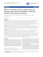
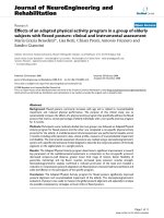
(see Table 2). The evolution of the computation t ime
for the four volumes can be observed in Figure 1. It can
be noted that the GPU co mputation time on machine 1
is also faster than the CPU on machine 2.
Regarding the computation time, it can be noted that
an increase of a factor 30 in the number of GPU cores
leads to a relatively weak performance gain. However,
the processing times on the Quadro NVS and on the
GTX GPU are 360 and 47 ms, respectively, for a work-
ing 2D + t volume of dimension 128 × 64 × 256. Those
times also consider the memory t ransfer time since it is
notpossibletoallocatedirectlyontheGPUthewhole
3D + t volume.Indeed,theworkingvolumeiscom-
posed approximately of two million voxels. Adding a
dimension in the z-direction, for example 50 points,
leads to a 3D + t volume containing more than 100 mil-
lion voxels. This amount of data has to be considered
both for the fun damental and the second-harmon ic
components. Then, after each z step, the computed
working 2D + t volume has to be saved on the CPU
memory. These memory transfers are time consuming
and limit the performance of the proposed method. On
both t he GPUs, the total memory transfers take around
27 ms, me aning that the performance of the GTX GPU,
considering only the execution time is 16.5 better than
the Quadro NVS board.
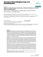
4.2 Resulting fields
One possible application of the GASM is to calculate
the pressure evolution in a medium with an inhomoge-
neous nonlinear coefficient. In such case s, the sec ond
harmonic pressure is expected to sharply increase
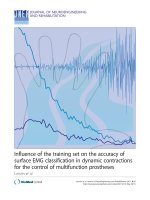
according to the nonlinear parameter. For example, Fig-
ure 2 shows the ultrasound fundamental and second
harmonic fields computed in a plane in which the n on-
linear parameter, b, abruptly changed from 3.5 to 35.
The peak pressures estimated in two different planes (x
=0andy = 0) are shown according to a color bar. As
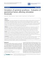
Table 1 Illustration of the different steps of the GASM
p
0
® P
0
® [FT]
For each z point:
P
0
® P
1
® [rotation kernel]
P
1
® p
1
(z) ® [IFT]
Compute bp
1
2
® [bp
1
2
kernel]
bp
1
2
® F(bp
1
2
) ® [FT]
Rotate F ( bp
1
2
) ® [rotation kernel]
Compute integral I ® [integral kernel]
I ® P
2
® [rotation kernel]
P
2
® p
2
(z) ® [IFT]
The different FTs, IFTs, and kernels are represented in square brackets.
Table 2 Description of the two CPUs and GPUs used
Machine 1 Machine 2
CPU Processor name Intel Core2 Duo
T9400
Intel Xeon
E5220
Speed 2.53 GHz 2.27 GHz
Memory 3.48 GB 5.9 GB
GPU Name Quadro NVS 160M GTX 285
Global memory 256 MB 1024 MB
Number of
multiprocessors
130
Number of cores 8 240
0 1 2 3 4
5
0
10
20
30
40
50
60
7
0
Size of the 3D (x,
y
, t) volume [million voxels]
Computation time [s]
CPU machine 1
GPU machine 1
CPU machine 2
GPU machine 2
Figure 1 Computation time on the CPU (dotted lines) and GPU
(full lines) for the two different PCs. The curves with ‘o’
correspond to the laptop (machine 1) and the curves with ‘+’ to a
standard PC (machine 2). The total time takes into account for
calculating the complete 3D + t volume, which depends on the z
sampling. The number of points in the z-axis is 30.
Varray et al. EURASIP Journal on Image and Video Processing 2011, 2011:17
/>Page 4 of 6
expected, the nonlinear parameter has no impact on the
fundamental image (Figure 2a), but the pr essure of the
second harmonic field significantly increases in the
region where b is higher (Figure 2b).
5. Discussion and conclusions
Currently available ultrasound simulators, such as FieldII
[23], present two weak points: they consider linear propa-
gationonlyandtheyneedalongtimetoconductthesimu-
lation. The GPU implementation of the GASM aims at
solving both problems. The implementation of the GASM
on a GPU significantly decreases the computation time for
the fundamental and second harmonic components of an
ultrasound field. The GPU is particularly suitable for the
GASM because it uses the FFT lib rary designed f or parallel
computation as well as the kernel that makes calculations
voxel by voxel in a 3D image. The final increase in speed
measured on a laptop graphics card (Quadro NVS 160 M)
is 3.5. On a more recent and efficient GPU, the speed is
13.6 times faster. The algorithm proposed here could also
be extended to higher-order harmonics (third, fourth, etc.)
as only one kernel is needed to compu te the propagation
of each harmonic [24]. However, i t has been highlighted
that the time devoted to the memory transfers from the
GPU to the CPU is not negligible and that increasing the
GPU computational power is not sufficient to further
decrease the computation time. The number of memory
transfers could be decreased using GPUs with larger mem-
ory, as now featured even in s ome notebooks.
TheuseofGPUsforfastultrasoundsimulationis
indeed promising and paves t he way for the invest iga-
tion of new applications. For example, the so far
a)
b
)
Figure 2 Evolution of the pressure obtain ed in simulati on for inhomogen eous nonlinear medium. Two planes (x = 0 and y = 0) are
displayed for the fundamental (a) and the second harmonic (b) field. The limit between the two regions with different nonlinear parameters
corresponds to the probe axis of symmetry x =0.
Varray et al. EURASIP Journal on Image and Video Processing 2011, 2011:17
/>Page 5 of 6
prohibitively long parameter sweep that is needed for
optimization purposes becomes possible. Pasovic et al.
[25] have recently discussed the advantages of limiting
the level of second harmonics created during nonlinear
propagation. In this technique, an optimal limitation can
be achieved through a s pecific probe excitation, pro-
vided the amount of second harmonic that must be
compensated is previously quantified. A fast calculation
of the second harmonic component, as is possible with
the GPUs, reveals the possibility of adapting the second
harmonic reduction during clinical exams. Indeed, in
these cases, the probe or the medium movements
decrease the resulting reduction. If quick simulations
are possible, the optimization of the second harmonic
reduction can be conducted concurrently with t he exam
in order to adapt the reduction in real time.
One known limitation of the GASM concerns the
simulation bandwidth. For example, it is surely not ade-
quate for the needs of cMUT t ransducers [26], a new
ultrasound transducer technology that works with high-
wideband signals. One possibility would be div iding the
initial frequency band into multiple sub-bands and run-
ning the GASM over each of them. Of course, one
should check whether the total simulation time becomes
comparable to that of finite difference methods.
The GPU programming of the GASM shows a very
promising opportunity in time reduction simulation in
ultrasound. The GASM is the first method in ultrasound
that has been tested on a GPU and the results obtained
show several opportunities for future simulation tools
and applications.
Acknowledgements
Special thanks are extended to ANR-07 TecSan-015-01 MONITHER for
financial support. FVwas financially supported by the Franco-Italian University
with a VINCI and a Gallilée grant and by the Rhone-Alpes region with an
Explora’Doc grant.
Author details
1
Université de Lyon, CREATIS; CNRS UMR5220; INSERM U1044; INSA-Lyon;
Université Lyon 1; 7 av Jean Capelle, 69621 Villeurbanne, France
2
Electronics
and Telecommunications Department, Università degli Studi di Firenze, Via
Santa Marta 3, 50139 Firenze, Italy
Competing interests
The authors declare that they have no competing interests.
Received: 28 February 2011 Accepted: 1 November 2011
Published: 1 November 2011
References
1. Averkiou MA, Roundhill DN, Powers JE: A new imaging technique based
on the nonlinear properties of tissues. IEEE Ultrasonics Symposium 1997,
2:1561-1566.
2. Lee Y-S, Hamilton MF: Time-domain modeling of pulsed finite-amplitude
sound beams. J Acoust Soc Am 1995, 97(2):906-917.
3. Christopher PT, Parker KJ: New approaches to the linear propagation of
acoustic fields. J Acoust Soc Am 1991, 90(1):507-521.
4. Varslot T, Taraldsen G: Computer simulation of forward wave propagation
in soft tissue. IEEE Trans Ultrason Ferroelectr Freq Control 2005, 52(9):1473-82.
5. Varslot T, Masoy S-E: Forward propagation of acoustic pressure pulses in
3D soft biological tissue. Model Identification Control 2006, 27:181-200.
6. Dursun S, Varslot T, Johansen T, Angelsen BAJ, Torp H: Fast 3D simulation
of 2nd harmonic ultrasound field from arbitrary transducer geometries.
IEEE Ultrasonics Symposium 2005, 1964-1967.
7. Yan X, Hamilton MF: Angular spectrum decomposition analysis of second
harmonic ultrasound propagation and its relation to tissue harmonic
imaging workshop. 4th International Workshop on Ultrasonic and Advances
Methods for Nondestructive Testing and Material Characterization 2006.
8. Wojcik J, Kujawska T, Nowicki A, Lewin PA: Fast prediction of pulsed
nonlinear acoustic fields from clinically relevant sources using time-
averaged wave envelope approach: comparison of numerical
simulations and experimental results. Ultrasonics 2008, 48(8):707-15.
9. Du Y, Jensen H, Jensen JA: Simulation of second harmonic ultrasound
fields. IEEE Ultrasonics Symposium San Diego; 2010.
10. Chang L-W, Hsu K-H, Li P-C: GPU-based color Doppler ultrasound
processing. IEEE International Ultrasonics Symposium 2009, 1836-1839.
11. Kiss G, Nielsen E, Orderud F, Torp HG: Performance optimization of block
matching in 3D echocardiography. IEEE International Ultrasonics
Symposium 2009, 1403-1406.
12. Romero D, Martinez-Graullera O, Martin CJ, Higuti RT, Octavio A: Using
GPUs for beamforming acceleration on SAFT imaging. IEEE International
Ultrasonics Symposium 2009, 1334-1337.
13. Elnokrashy AF, Elmalky AA, Hosny TM, Ellah MA, Megawer A, Elsebai A,
Youssef ABM, Kadah YM: GPU-based reconstruction and display for 4D
ultrasound data. IEEE International Ultrasonics Symposium 2009, 189-192.
14. Kiss G, Steen E, Asen JP, Torp HG: GPU volume rendering in 3D
echocardiography: real-time pre-processing and ray-casting. IEEE
International Ultrasonics Symposium 2010, 193-196.
15. Kutter O, Shams R, Navab N: Visualization and GPU-accelerated simulation
of medical ultrasound from CT images. Comput Methods Prog Biomed
2009, 94(3):250-266.
16. Shams R, Luna F, Hartley RI: An algorithm for efficient computation of
spatial impulse response on the GPU with application in ultrasound
simulation. 2011 IEEE International Symposium on Biomedical Imaging: From
Nano to Macro 2011, 45-51.
17. Pinton G, Dahl J, Rosenzweig S, Trahey G: A heterogeneous nonlinear
attenuating full- wave model of ultrasound. IEEE Trans Ultrason Ferroelectr
Freq Control 2009, 56(3):474-488.
18. Karamalis A, Wein W, Navab N: Fast ultrasound image simulation using
the westervelt equation. Medical Image Computing and Computer-Assisted
Intervention Springer-Verlag, Beijing; 2010.
19. Varray F, Ramalli A, Cachard C, Tortoli P, Basset O: Fundamental and
second-harmonic ultrasound field computation of inhomogeneous
nonlinear medium with a generalized angular spectrum method. IEEE
Trans. Ultrason Ferroelectr Freq Control 2011, 58(7):1366-1376.
20. Du G, Breazeale MA: The ultrasonic field of a Gaussian transducer. J
Acoust Soc Am 1985, 78(6):2083-2086.
21. Belgroune D, de Belleval JF, Djelouah H: Modelling of the ultrasonic field
by the angular spectrum method in presence of interface. Ultrasonics
2002, 40(1-8):297-302.
22. Frigo M, Johnson SG: The design and implementation of FFTW3. Proc IEEE
2005, 93(2):216-231.
23. Jensen JA: Field: a program for simulating ultrasound systems. 10th
Nordic-Baltic Conference on Biomedical Imaging Published in Medical &
Biological Engineering & Computing 1996, 351-353.
24. Pasovic M, Danilouchkine M, Van Neer P, Basset O, Cachard C, Van der
Steen AFW, De Jong N: Angular spectrum method for the estimation of
the lateral profile of the ultrasound pressure field in the super harmonic
band. IEEE Ultrasonics Symposium, Rome 2009.
25. Pasovic M, Danilouchkine M, Matte G, van der Steen AFW, Basset O, de
Jong N, Cachard C: Broadband reduction of the second harmonic
distortion during nonlinear ultrasound wave propagation. Ultrasound
Med Biol 2010, 36(10):1568-1580.
26. Mills DM: Medical imaging with capacitive micromachined ultrasound
transducer (cMUT) arrays. Ultrasonics Symposium, 2004 IEEE 2004, 1:384-390.
doi:10.1186/1687-5281-2011-17
Cite this article as: Varray et al.: Simulation of ultrasound nonlinear
propagation on GPU using a generalized angular spectrum method.
EURASIP Journal on Image and Video Processing 2011 2011:17.
Varray et al. EURASIP Journal on Image and Video Processing 2011, 2011:17
/>Page 6 of 6