Advanced Transmission Techniques in WiMAX Part 14 docx
Bạn đang xem bản rút gọn của tài liệu. Xem và tải ngay bản đầy đủ của tài liệu tại đây (1.11 MB, 21 trang )
Advanced Transmission Techniques in WiMAX
316
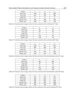
Fig. 26. Debit of HO from 802.16e to 802.11s / Video
With the video traffic, the debit values decrease comparing to the other traffic types.
5. Conclusion
The interoperability and the vertical handover between different networks present currently
a real challenge to overcome. The difference of networks operation is the main reason of this
problem. And, for pass to the 4G networks, it is important to resolve this problem of
interoperability between different networks.
Our work has focused on the interconnection between two wireless radio networks of the
IEEE 802 family, and we are concentrating on the QoS aspect for several traffics types
especially during the handover process. For doing that, we have proposed two
interconnection models based on two recent handover mechanisms, and we have simulated
those two models with three mobile speeds and in the both directions of networks.
Observing the results obtained, we can conclude that with a low or medium speed of
displacement of a mobile station, the both techniques: IEEE 802.21 and MSCTP present a
good solution during the vertical handover. With the two techniques, there are very few
interruptions during the vertical handover. But based on details of simulation results, we
notice that with MSCTP protocol we obtained a QoS level slightly better than that obtained
with MIH architecture.
Interaction and Interconnection Between 802.16e & 802.11s
317
Also the handover from 802.11s to 802.16e generates results better than the opposite case of
handover. But with a high speed, it is the opposite rather because the mobile WIMAX
supports better the increasing speeds; and also the results in this case are still not acceptable
comparing by QoS level needed for each traffic type.
It should be noted that during all the simulations, the scenarios proposed does not include
cell congestion or lack of available resources.
For future work, we will propose interconnection models between networks of different
family, we will mix a network world with a telecommunication world, and we will try to
propose a handover mechanism adapted to the two entities that we will define.
6. References
[1] The Information Science Institute (ISI), “The Network Simulator-NS-2”,
nsnam/ns/.
[2] EEE Std, “Air Interface for Fixed and Mobile Broadband Wireless Access Systems,” IEEE
802.16e, Part 16, February 2006.
[3] IEEE Std, “Air Interface for Fixed Broadband Wireless Access Systems,” Local and
metropolitan area networks, Part 16, 2004.
[4] arviz Yegani, “WiMAX Overview,” White paper, IETF-64 Cisco Systems, 2005.
[5] WiMAX Forum, “WiMAX End-to-End Network Systems Architecture,” Draft Stage 2:
Architecture Tenets, Reference Model and Reference Points, June 2007.
[6] Steven Conner, Jan Kruys, Kyeongsoo Kim and Juan Carlos Zuniga, “IEEE 802.11s
Tutorial,” Overview of the Amendment for Wireless Local Area Mesh Networking,
IEEE 802 Planary, November 2006.
[7] Guido R. Hiertz, Sebastian Max, Rui Zhao, Dee Denteneer and Lars Berlemann,
“Principles of IEEE 802.11s,” Computer Communications and Networks, 2007,
ICCCN 2007.
[8] RFC 2960, “Stream Control Transmission Protocol,” IETF, 2000.
[9] Stewart R., & al., IETF, “Stream Control Transmission Protocol (SCTP) Dynamic Address
Reconfiguration,” IETF Internet, Draft, draft-ietf-tsvwg-addip-sctp-13.txt, November
2005.
[10] Koh, S., & al., “mSCTP for Soft Handover in Transport Layer,” IEEE Communication
Letters, Vol. 8, No.3, pp.189-191, March 2004.
[11] Memory graduation, Esteban Zimanyi, “Performance analysis of vertical Handover
between UMTS and 802.11 networks,” 2005.
[12] Deng Feng, “Seamless Handover between CDMA2000 and 802.11 WLAN using
mSCTP,” Thesis, 2006.
[13] IEEE 802.21 tutorial, July 2006.
[14] Jared Stein, “Survey of IEEE 802.21 Media Independent Handover Services,” April 2006.
[15] V. Gupta, “IEEE 802.21 standard and metropolitan area networks: Media Independent
Handover services”, Draft P802.21/D05.00, April 2007.
[16] K. Leung, G. Dommety, P. Yegani & K. Chowdhury, “Mobility Management Using Proxy
Mobile IPv4”, Internet Draft, IETF, 2007.
Advanced Transmission Techniques in WiMAX
318
[17] Information Sciences Institute (ISI), “NSNAM web pages, 18.2 Two-Ray Ground reflection
model,” January 2009.
[18] WiMAX Community, “WiMAX fundamentals, 1.7.3 Quality of Service”, June 2007.
15
Inter-Domain Handover in WiMAX Networks
Using Optimized Fast Mobile IPv6
Seyyed Masoud Seyyedoshohadaei,
Borhanuddin Mohd Ali and Sabira Khatun
Universiti Putra Malaysia (UPM),
Malaysia
1. Introduction
The most attractive feature of WiMAX is arguable the mobility capability that IEEE 802.16e
(IEEE, 2004) standard adds to the previous standard. With mobility support, handover has
become one of the most important factors that impact the performance of IEEE 802.16e
system. Handover is the process of maintaining active sessions of a mobile station when it
migrates from current base station to target base station area. Handover occurs when a
mobile station changes its point of attachment on the network. However during hard
handover, the mobile station cannot receive or send any packet for a short time interval.
This is referred to system disruption time because the services are interrupted or handover
latency. In WiMAX, when a mobile node or mobile station changes its location, it moves the
point of attachment to the network in two different scenarios;
The mobile station changes its point of attachment between the base stations which
reside in the same Access Services Network (ASN) that is called ASN-anchored, intra,
micro, or layer 2 handover. In an ASN-anchored handover, the mobile station resides
within previous network address (both current and target base stations located in the
same IP subnet). In this scenario, the mobile station does not change its IP
configuration, only link layer is re-established.
The mobile station or mobile node changes its point of attachment between the base
stations which reside in different ASN (different IP subnets) that is called Connectivity
Services Network (CSN)-anchored, inter, macro, or layer 3 handover. In a CSN-
anchored handover, in addition to link layer handover a mobile node must perform a
new IP configuration to avoid disconnection.
The intra-domain handover procedure requires support from the physical and MAC layers.
IEEE 802.16e has its own MAC layer or layer 2 handover algorithm, but a layer 3 handover
algorithm is also required to support the Internet Protocol (IP) addressing, for inter-domain
handover. A typical protocol in network layer for mobile terminals is Mobile IP include
Mobile IPv4 (MIPv4), (IEEE, 2002) and Mobile IPv6 (MIPv6), (IEEE, 2004) that have been
standardized by the Internet Engineering Task Force (IETF). There are many problems
associated with MIPv4, such as triangular routing, security and limitation of address space
which were solved by using MIPv6. But there still remain some other problems, such as long
service disruption time (handover latency), signalling overhead and packet loss.
Advanced Transmission Techniques in WiMAX
320
However, MIPv6 does not solve the handover latency problem which is not negligible for
real-time applications such as video streaming and Voice over IP (VoIP). Proxy Mobile IPv6
(PMIPv6), Hierarchical Mobile IPv6 (HMIPv6) and Fast Mobile IPv6 (FMIPv6) have been
proposed to decrease long handover latency of MIPv6. The MIPv6 Signalling and Handoff
Optimization (MIPSHOP) working group has standardized FMIPv6 (IETF, 2005). FMIPv6 is
capable decreasing the handover latency and packet loss by mobility detection and creating
new address for the target network and receives data through tunnelling in advance.
Because of this, FMIPv6 is used as IP layer protocol in WiMAX. However, due to complexity
of handover pattern, designing an impressive handover process to support all mobility
scenarios with acceptable latency is still a challenge. There have been many proposals on
how to effectively coordinate the FMIPv6 handover algorithm in layer 3 with handover
algorithm of the IEEE 802.16e system in layer 2. To overcome some of the shortcomings in
the proposed proposals an Optimized Fast Handover Scheme (OFHS) is proposed and
presented in this chapter.
This chapter is organized as follows. In section 2, the MIPv6, FMIPv6, IEEE 802.16e
handover and related works are described. The proposed scheme is explained in section 3.
In section 4, a numerical model is developed to evaluate the performance of OFHS
compared with that of RFC5270 (IEEE, 2008). T The results and discussion are presented in
section 5, and finally, in section 6, conclusions of this chapter are made.
2. Background and previous works
In this section first, some literature that needed to explain proposed method such as mobile
IP and the layer 2 handover procedures in IEEE 802.16.e or mobile WiMAX are described.
Then some related works are introduced which have focused on how apply FMIPv6 over
IEEE 802.16e to support inter-domain handover.
2.1 Background
When a host moved to other subnet, the IP address became incorrect for routing and if hosts
used new IP address the connections would be terminated because the new IP address was
unknown. Mobile IP mechanism works based on a temporary IP address named Care of
Address (CoA). The MIPv4 and MIPv6 have introduced for difference IP addressing. In this
work IPv6 has been used for addressing. Therefore, in following sections (2.1.1 and 2.1.2)
MIPv6 and Fast MIPv6 are described.
The IEEE 802.16e standard supports mobile user in WiMAX network. It supports only intra-
domain handover that movement of the mobile station with in same subnet does not affect
the IP address. In section 2.1.3, layer 2 handover procedure that has been defined in IEEE
802.16e explined.
2.1.1 Mobile IPv6
The MIPv6 is a protocol to support inter-domain mobility (in network layer) for IPv6 based
network. In MIPv6, the packets that are sent to the mobile node from the correspondent
node are intercepted and forwarded by a home agent. The MIPv6 has same functions as
MIPv4 that is adapted for MIPv6.
Inter-Domain Handover in WiMAX Networks Using Optimized Fast Mobile IPv6
321
In MIPv6 also, each mobile node has two addresses, a static home address under its home
network (HoA), and a care of address (CoA) as the mobile node roams to a foreign network
for packet routing. The mobile node can create a CoA from a router advertisement message
sent by the new visited network. When the mobile node moves to a foreign network, the
mobile node sends Binding Update (BU) messages with its CoA to the home agent in order
to update the home agent of its current point of attachment. In this way, mobile node’s
home agent can always detect coming communication packets to mobile node with home
address of mobile node, and dispatching these packets to the mobile nodes’ CoA via
dynamically created IP tunnels. The signalling and data traffic are all transmitted via a
unified IP framework, because, all the MIPv6 signalling messages are formed by extending
IP protocols with option headers. However the MIPv6 causes a long latency problem. In
order to improve handover performance of MIPv6, IETF introduced some IPv6 mobility
protocol solutions such as HMIPv6 and FMIPv6.
2.1.2 Fast mobile IPv6
In MIPv6, the movement detection (based on Router Advertisement in IP-layer) and the
address configuration procedures cause a long latency problem. FMIPv6 decreases delay of
the movement detection and the address configuration phases of MIPv6. It enables the
mobile node to provide the target base station identifier (BSID) and detects upcoming
entrance to new subnet. It therefore reduces delay of movement detection. For new address
configuration, in the FMIPv6 the mobile node obtains the new associated subnet prefix
information in advance, while it is still connecting to the current subnet.
After the mobile node select one of the candidate base stations as target base station
according to its policy, it sends the Router Solicitation for Proxy (RtSolPr) to the current
access router or previous access router and receives Proxy Router Advertisement (PrRtAdv)
messages in return. During exchanges of these messages the mobile node obtains the subnet
prefix of the target base station. The current base station configures a new IP address (CoA)
based on the subnet prefix of the target base station. After that, the mobile node sends a Fast
Binding Update (FBU) message to the previous access router. The purpose of FBU messages
is to inform the access router that there is a binding between the current CoA at the current
subnet and the new CoA (NCoA) at the target subnet. Then, the Handover Initiation (HI)
message is sent to the target or new access router by previous access router. The new access
router performs duplicate address detection (DAD) to check validity of NCoA. After DAD
procedure the new access router reply with handover acknowledge (HAck) message to the
current access router. At this instant, a tunnel between the CoA of and NCoA of mobile
node is established. The previous access router sends a fast-binding acknowledgement
(FBAck) message to new access router. Fig. 1 illustrates the FMIPv6 procedure for Predictive
and Reactive mode. If the mobile node receives the FBAck message in the current subnet
before the layer 2 handover is started (there is enough time to exchange required messages
to establish tunnel), handover occurs in the predictive mode. Otherwise, if the mobile node
is forced to move to the new access router without receiving FBAck, FMIPv6 is in reactive
mode.
In the predictive mode, the previous access router first store the tunnelled packets in a
buffer. After the mobile node attaches to the new link, mobile node sends a Fast Neighbour
Advanced Transmission Techniques in WiMAX
322
Advertisement (FNA) message to the new access router. Upon reception of an FNA
message, the new access router delivers the buffered packets to the mobile station In
reactive mode, mobile node receives packets from the new access router after the packets are
rerouted from previous to new access router.
Fig. 1. FMIPv6 Procedure Predictive mode and Reactive Mode
2.1.3 IEEE 802.16e link layer handover
The IEEE 802.16e layer 2 handover procedure can be divided into two steps: handover
preparation and handover execution. Fig. 2 illustrates the IEEE 802.16e handover procedure.
The handover preparation can be initiated by either mobile station or base station. During
this period, the neighbouring base stations are compared according to its policy. Some
metrics such as Quality of Service (QoS) parameters or signal strength are considered to
target base station selection. The current base station periodically sends the neighbour
advertisement (MOB_NBR-ADV) messages to mobile stations. This message contains
information about neighbouring base stations, and the mobile station is capable to select
target base stations for a future handover. In order to search for the suitability of
neighbouring base stations, mobile station may execute a scanning operation (if necessary).
It sends MOB_SCN-REQ to current base station to obtain neighbouring base stations
information and the base station reply by MOB_SCN-RSP message. After a mobile station
decides to perform handover, it sends a MOB_MSHO-REQ message contain candidate base
station identity to the current base station. The current base station negotiates with
candidate base stations with exchanges HO-pre-notification and HO-pre-notification-
response messages. Then the current base station introduces the recommended base stations
by sending an MOB_BSHO-RSP message to mobile station.
The handover execution is started by sending an MOB_HO-IND message from mobile
station to the current base station. This message contains selected target base station, and
after that packet exchanging between mobile station and current base station is terminate.
After IEEE 802.16e network entry process, the mobile station tuned its own parameters to
the target base station. The buffered packets are sent to the mobile station from the target
base station (it now becomes current base station). If the new base station has a new IP
address, a network layer handover mechanism is needed.
FB
NA
R
PAR
MOBILE
NODE
FNA(FBU
)
FBac
k
RtSol
PrRtAd
Forward Packets
Delivered Packets
NAR PAR
MOBILE
NODE
FNA
HAck
HI
FBack FBack
RtSolPr
PrRtAd
FBU
DAD
Forward Packets
Delivered Packets
Inter-Domain Handover in WiMAX Networks Using Optimized Fast Mobile IPv6
323
Fig. 2. IEEE 802.16e handover procedure
2.2 Related research works
The reduction of inter-domain handover latency in IEEE 802.16e handover process had been
presented in several papers. A link layer optimized scheme that reduces the link-layer
handover latency by analyzing and optimizing each step of the procedure is suggested in
(Lee, D. et al., 2006). In principle, the overall handover latency does not decrease by simple
reduction of the link layer latency. To solve this problem, a cross-layer fast handover scheme
for the IEEE 802.16e system is proposed in (Han et al., 2007). It coordinates FMIPv6 with
IEEE 802.16e handover procedure to reduce the handover latency. This scheme with a little
change is used in RFC5270 (IETF, 2008).
2.2.1 RFC 5270
FH802.16e is a cross layering design for FMIPv6 handover over IEEE 802.16e. One-way
signaling is used in the majority of the existing cross layering handovers researches. They
usually defined cross layer signals from MAC layer to IP layer. In the Han et al. scheme,
two-way signaling between MAC layer and IP layer is defined. This concept helps to
achieve faster handover algorithm than previous algorithms. For efficient handovers and
reduce the handover latency the authors introduce one command and three events. Same
events and command have been proposed in the IEEE 802.21 Media Independent Handover
(MIH) (IETF, 2007). They support the interaction between both IP and MAC layers handover
procedures. The event are defined as follows:
NEW_CANDIDATE_BS_FOUND: this includes the BSID(s) of candidate base station(s) and
is sent by MAC layer to IP layer (FMIPv6) when a new base station(s) is found.
Advanced Transmission Techniques in WiMAX
324
LINK_GOING_DOWN: This is sent by MAC layer to IP layer (FMIPv6) when a mobile node
receives an MOB_BSHO-REQ or an MOB_MSHO-RSP message which includes the target
BSID. Upon receiving this event, the IP layer of the mobile node performs the handover
preparation by sending an FBU message to the current access router.
LINK_SWITCH: This is sent by IP layer (FMIPv6) to MAC layer when the IP layer of a
mobile node receives an FBAck message. It caused the mobile node MAC layer start
handover execution by sending an MOB_HO-IND message to the current base station.
LINK_UP: This is sent by MAC layer to IP layer (FMIPv6) to inform layer 3 that the network
re-entry procedure of IEEE 802.16e is terminated. Upon receiving this event, the IP layer of
mobile node sends an FNA message.
The scheme proposed in this article provides RFC5270 and the names of triggers change to:
New Link Detected (NLD), Link Handover Impend (LHI), Link Switch (LSW), and Link Up
(LUP). Fig. 3 and Fig. 4 show the message sequence diagram of the predictive and reactive
FMIPv6 handover initiated by the RFC5270. The handover procedure of RFC5270 consists of
two stages: handover preparation and handover execution. Just as FMIPv6 that supports all
inter-domain handover scenarios, two modes (predictive and reactive) are defined in
RFC5270.
Fig. 3. FMIPv6 over IEEE 802.16e, Predictive Mode
Predictive Mode: Here, the current base station generates and broadcasts a Mobile
Neighbor Advertisement (MOB_NBR-ADV) message periodically. It contains the network
topology and static link layer information. When the mobile node discovers a new base
HAck
T
N0G
UNA
LUP
NLD
LS
W
MOB
-
HO
-
IND
FBac
k
FBac
k
HIFBU
LHI
M
O
B-B
S
H
O
-R
S
P
MOB-MSHO-RE
Q
PrRtAdv
RtSolP
r
MOB
-
NBR
-
ADV
NAR
Target
BS
PAR
Current
BS
MN
L2
MN
L3
IEEE 802.16e network entry
DAD
Scanning
Forward Packets
Delivered Packets
T
L2
T
L3
T
DEL
T
IND
T
HI
Inter-Domain Handover in WiMAX Networks Using Optimized Fast Mobile IPv6
325
station in this message, a scanning may be performed to acquire more dynamic parameters
for the new base stations. If the newly found base stations are candidates for the target BSs,
the NLD event is delivered to its IP layer from the mobile node MAC layer with the found
BSIDs. The Router Solicitation Proxy (RtSolPr) message and Proxy Router Advertisement
(PrRtAdv) messages are exchanged between the mobile node and previous access router.
The terminal initiates handover by sending a Mobile Handover Request (MOB_MSHO-
REQ) message to the current base station and receives a Mobile Handover Response
(MOB_BSHO-RSP) message in reply with a target base station in it. The current base
station may also initiate handover by sending a MOB_BSHO-REQ message to the mobile
node.
Fig. 4. FMIPv6 over IEEE 802.16e, Reactive Mode
After the mobile node receives MOB_BSHO-REQ or MOB_BSHO-RSP from the base station,
the IP layer is triggered by link layer through a LHI to send Fast Binding Update (FBU) to
the previous access router. The Handover Indication (HI) and Handover indication
Acknowledge (Hack) messages are exchanged between previous and new access routers.
The duplicate address detection is performed by new access router (it validates the
uniqueness of NCoA in the new subnet, establishes tunnel and sends Fast Biding
Acknowledge (FBack) message to the mobile station. Once the tunnel is established, the
packets that are destined for the mobile node CoA are forwarded to the NCoA at the new
access router through the tunnel. Upon receiving the FBack, the mobile node link layer is
signalled by its network layer through a LSW to manage handover by sending a Mobile
Advanced Transmission Techniques in WiMAX
326
handover indication (MOB-HO-IND) message to the target base station. This message starts
the 802.16e network re-entry process. After re-entry process, the mobile node link layer
triggers its network layer with a LUP to send Unsolicited Neighbor Advertisement (UNA)
message to the new access router. When the new access router receives the UNA from the
mobile node, it delivers the buffered packets to the mobile node.
Reactive Mode: If the mobile node sends the MOB-HO-IND message to the base station
before receiving FBack, the mobile station carries out 802.16e network re-entry process
without establishing tunnel with selected NAR. At this instant, the mobile node cannot
perform predictive mode so it operates in reactive mode as follows. Upon the network
entry procedure completion, the link layer of mobile node sends LUP signal to the IP
layer. Then the IP layer identifies that it has moved to the target network without
receiving the FBack in the previous link. The mobile node sends an UNA to the new
access router by using NCoA as a source IP address and sends an FBU to the previous
access router. When the new access router receives the UNA and the FBU from the mobile
node, it sends the FBack to the previous access router, and the packets that have been
forwarded from the previous access router to new access router are delivered to the
mobile node (through NCoA) through the new access router.
2.2.2 Cross Layer Handover Scheme (CLHS)
(Chen & Hsieh, 2007) suggested an integrated design of layer 2 and layer 3 called Cross
Layer Handover Scheme (CLHS). The main idea of the CLHS is that if the handover
procedures of layer 2 and layer 3 can be coincident, the overall overhead of handover will be
decreased. In the CLHS, the correlated messages of IEEE 802.16e and FMIPv6 were
integrated. The authors show that some FMIPv6 handover information can be exchanged
with the messages of IEEE 802.16e. The messages which have the same characteristics
during handover procedure are merged. They are described as follows:
FBU-MOB_HO-IND: The original MOB_HO_IND message are modified to include FBU as a
new message. There are 6 reserve bits in the MOB_HO_IND message of link layer. One bit
of them is used to indicate that the FBU is enabled or disabled. Upon receiving the FBU-
MOB_HO-IND message containing FBU bit, the current base station itself (instead of mobile
node) sends FBU message to previous access router.
FNA_RNG_REQ: The RNG_REQ message of 802.16e contains 8 reserved bits. They are used
to send the information of FNA message of FMIPv6 in reactive mode.
In addition to the two messages, the neighbour advertisement message of layer 3 and the
ranging request message of layer 2 were modified and merged. The MOB_NBR_ADV
message in IEEE 802.16e and the PrRtAdv message in FMIPv6 have similar functionality.
Hence, the CLHS merges these two messages together. The FBack massage of IP layer is
combined with the Fast Ranging IE of link layer. Fig. 5 shows message sequence of the
CLHS.
2.2.3 Integrated fast handover in IEEE 802.16e (IFH802.16e)
The IFH802.16e proposes a handover scheme for FMIPv6 over the IEEE 802.16e system by
integrating FMIPv6 with IEEE 802.16e system. The IFH802.16e used same preparation
Inter-Domain Handover in WiMAX Networks Using Optimized Fast Mobile IPv6
327
concept as the previous works. In the IFH802.16e, the previous access router is informed by
base station to imitate IP layer handover on behalf of the mobile node.
Fig. 5. CLHS procedure
3. Optimized Fast Handover Scheme (OFHS)
In this scheme, pre-established tunnelling mechanism to reduce handover preparation time
is used. In addition, a set of messages has been defined to interleave layer 2 and layer 3
procedure. Cross layer design and cross function optimization are used to improve
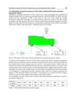
handover performance. The network model is as shown in Fig. 6.
In the OFHS, the serving base station periodically generates and sends the MOB_NBR-ADV
message to mobile stations. The MOB_NBR-ADV message of IEEE 802.16e and the PrRtAdv
message of FMIPv6 have similar functionality. The information of both messages can be sent
through the MOB_NBR-ADV message. Hence, these messages are merged and the PrSolPr
message can be eliminated. The mobile station may also perform scanning to obtain link
characteristics to evaluate whether to perform handover or otherwise. After the scanning
procedure, mobile station selects target base stations among the candidate base stations,
based on signal strength, QoS, service price and etc.
Advanced Transmission Techniques in WiMAX
328
If handover is needed, the mobile station sends the MOB_MSHO-REQ message to the
possible target base stations that are listed. Then the current base station negotiates with the
candidate base stations, and sends the recommended base stations and to mobile station
through the MOB_MSHO-RSP message. At the same time the current base station sends the
handover notification (HO-NOTIF) message to previous access router. The HO-NOTIF
message let the previous access router to start the layer 3 handover. It contains the identities
of the recommended base stations and the MAC address of the mobile station. After
receiving this message, the previous access router initiates the FMIPv6 handover by sending
the handover initiate (HI) message to the next access router associated with target base
station. The HI message should contain the NCoA of the mobile station when the stateless
address auto-configuration (Thomson et al, 2007) is used. In the OFHS, the NCoA is
configured by using the MAC address of the mobile node and the network prefix of new
access router. It is performed by previous access router on behalf of the mobile station. The
previous access router already knows the network prefix of new access router through some
auxiliary protocols (Kwon et al., 2005; Liebsch et al., 2005).
Fig. 6. Network Model
The previous access router exchanges HI and handover acknowledge (HAck) messages with
new access router. During this process, a tunnel between the previous and new access
routers is set up and the validity of the NCoA is checked with duplicate address detection
(DAD). The established tunnel may be more than one based on the recommended base
stations. The tunnels are inactive and one of them will be activated only when previous
access router receives the handover confirmation (HO-CONFRIM) message that includes the
target base station. Once the tunnels are established, previous access router sends an FBack
to the mobile station. FBack is applied to inform the status of the configuration of CoA.
FBack are sent by the target base station so that the mobile station can be informed that the
next CoA is valid. The mobile station can send a MOB-HO-IND message to the target base
Inter-Domain Handover in WiMAX Networks Using Optimized Fast Mobile IPv6
329
station according to the policy and then carry out IEEE 802.16e network re-entry process. If
the FBack is received by the mobile station before sending MOB-HO-IND message,
handover continues in predictive mode. The MOB-HO-IND message contains selected
target base station and the MAC address of the mobile station. The current base station
notifies the new access router of the target base station by sending the HO-CONFIRM
message. The previous access router obtains the exact target base station and related access
router by receiving the HO-CONFIRM message. The previous access router starts
forwarding the packets destined to the mobile station through one of the tunnels while the
other tunnels that are not selected are discarded.
The new access router buffers the packets during the network re-entry procedures. In this
scheme layer 3 handover is initiated at the network side while the mobile station performs
the layer 2 handover. Because the mobile station is not involved in formulating the NCoA, it
should be informed of NCoA. This can be realized by sending the HO-COMPLETE message
from target base station to the new access router after the network re-entry procedures of
IEEE 802.16e. The target base station sends the REG-RSP message to mobile station and
finalizes the network re-entry procedures of IEEE 802.16e and sends HO-COMPLETE
message to confirm the layer 3 handover of mobile station. Upon HO-CONFIRM message
received by the next access router, it starts delivering the buffered packets to the mobile
station. The HO-COMPLETE message is necessary because after the mobile station
performed layer 2 handover the NCoA should be notified to the mobile node. The new
access router must send the Unsolicited Router Advertisement with Neighbor
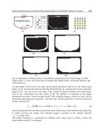
Advertisement Acknowledgement option to the mobile node. Fig. 7 shows OFHS predictive
mode.
Fig. 7. OFHS Handover Procedure, Predictive Mode
Advanced Transmission Techniques in WiMAX
330
If the mobile node sends MOB-HO-IND message to the current base station before receiving
FBack (before establishing tunnel with selected access router), the mobile station starts IEEE
802.16e network re-entry process and the current base station sends HO-CONFIRM message
to the previous access router. The previous access router stops sending packets to the mobile
node and starts to buffer the packets destined for the mobile station. During the network re-
entry procedures of IEEE 802.16e or after that, the previous access router receives the HAck
message. There are two scenarios; first, if the previous access router receives HAck messages
from the new access router before the end of network re-entry procedures of IEEE 802.16e,
the previous access router starts to tunnel the packets destined for the current CoA to the
new CoA at the new access router. Then the new access router starts delivering the packets
to the mobile station. The previous access router already knows the exact target mobile
station and its associated access router, therefore, the previous access router can determine
through which tunnel it should start forwarding the packets destined to the mobile station
while the other tunnels that are not used will be discarded. The second scenario is that, if the
network re-entry procedure of IEEE 802.16e is terminated and the tunnel with selected new
access router has not been established yet, the previous access router waits to receive HAck
message from the new access router. Upon receiving the HAck message, the previous access
router starts to tunnel the packets (destined for the current CoA) to the NCoA at the new
access router. Then the new access router starts delivering the tunnelled packets to the
mobile node. These two scenarios are called semi-predictive mode defined in OFHS instead
of reactive mode defined in the RFC5270. The semi-predictive mode procedure is shown in
Fig. 8.
Fig. 8. OFHS Handover Procedure, Semi-Predictive Mode
Inter-Domain Handover in WiMAX Networks Using Optimized Fast Mobile IPv6
331
4. Performance evaluation
In order to evaluate the performance of the proposed method, a numerical model has been
developed. In this chapter, the important metrics for evaluating the handover mechanism are
total handover procedure time and handover latency respectively. In the evaluation, the OFHS
is compared with the RFC5270 as the reference procedure for using FMIPv6 in WiMAX.
To analyze the performance model of the proposed scheme, the duration of each part of the
handover procedure are considered. The message interaction is based on the duration of a
frame which is an OFDMA type used by IEEE 802.16e air interface. The frame duration is
assumed to be at least 1ms and processing time is ignored since it is less than the frame
duration. On the other hand, the network nodes message transmission delay is at least a
frame long (>1ms). The radio propagation delay is assumed to be smaller than the frame
duration, so it is omitted.
4.1 Total handover procedure time
The total handover procedure time (T
THT
) is defined as the elapsed time between a mobile
node sending the
MOB_MSHO-REQ message to the current base station and the time the
mobile station can receive the first packet through the target access router. T
TH-PM-RFC
and
T
TH-PM-OFHS
are defined as the total handover time of the predictive mode in RFC5270 and
OFHS, respectively. The Equations are defined in term of delay of every routing hop in a
wired backbone (T
HOP
) and frame duration of IEEE 802.16e (T
F
). Negotiation between the
current base station and the target base station is started by sending MOB-MSHO-REQ.
Then the current base station sends handover notification message to target base station and
receives handover notification response from it. The procedure is concluded by sending
MOB-BS-HO-RSP to current base station. The time lag from the point of sending MOB-
MSHO-REQ to receiving MOB-BSHO-RSP or negotiation delay between the current and
recommended base stations (T
NEG
) is given by Equation (1). The time required to perform
FMIPv6 in layer 3 from the point of sending FBU to receiving FBack is T
L3
and the latency of
IEEE 802.16e network re-entry procedure is given by T
L2
.They are expressed in Equations (2)
and (3), respectively. N
PAR-NAR
is the distance between the previous and new access routers
in term of number of hops and T
DAD
is time needed to complete a duplicate address
detection procedure. The MAC layer handover time is based on the number of messages
exchanged between mobile station and base stations according to the RFC5270. Packet
delivery time (T
DEL
) is the time required from the point of sending the UNA message after
IEEE 802.16e handover to receiving the first packet from new access router; this is given by
Equation (4).
T
NEG
=4T
HOP
+2N
PAR-NAR
×T
HOP
(1)
T
L3-RFC
=3T
F
+ 2T
HOP
+2N
PAR-NAR
× T
HOP
+ T
DAD
(2)
T
L2
= 10T
F
+ 30 (ms) (3)
T
DEL-RFC
= 3T
F
+ 2T
HOP
(4)
The elapse time between receiving MOB-BSHO-RSP and starting layer 3 handover is given
by T
HI
(For RFC5270 procedure T
HI
= 2T
F
). T
IND
is elapse time between receiving FBack and
sending MOB-HO-IND. To simplify analysis, fixed delay time for T
IND
is assumed.
Advanced Transmission Techniques in WiMAX
332
The message interaction is based on the duration of a frame, all times expressed as integer
number of frame. Therefore, all non-integer times is rounded to the next nearest integer
number (this is shown as [ ]
F
). In OFHS, T
NEG
, T
L2
and T
DEL
are the same as Equations (1), (2)
and (3), and T
L3
is obtained from Equations (5). Hence, the total handover time of the
predictive mode in term of T
F
for RFC5270 and OFHS are given by Equation (6) and (7),
respectively.
T
L3-OFHS
= T
F
+2 T
HOP
+2 N
PAR-NAR
× T
HOP
+T
DAD
(5)
T
TH-PM-RFC
=T
NEG
+T
HI
+T
L3-RFC
+T
IND
+T
L2
+T
DEL-RFC
(6)
=[4T
HOP
+2 N
PAR-NAR
×T
HOP
]
F
+18T
F
+ [2T
HOP
]
F
+
+[2T
HOP
+2N
PAR-NAR
×T
HOP
+T
DAD
]
F
+T
IND
+30(ms)
T
TH-PM-OFHS
=T
NEG
+T
L3-POR
+T
IND
+T
L2
+T
DEL-POR
(7)
= [4T
HOP
+2N
PAR-NAR
×T
HOP
]
F
+12T
F
+
+[2T
HOP
+2N
PAR-NAR
× T
HOP
+T
DAD
]
F
+
+T
IND
+30(ms) + [T
HOP
]
F
T
TH-RM-RFC
is the total handover time of the reactive mode of the RFC 5270 and T
TH-SPM-OFHS
as
the total handover time of the semi-predictive mode of the OFHS given by Equations (8) and
(9) respectively. In reactive mode, after sending FBU, the mobile node does not receive an
FBAck from the current access router before the mobile node is forced to move to the target
access router. The mobile station must wait for packet rerouting before it can receive any
packets from the target access router. T
FNA
is elapse time between layer 2 handover
termination and FNA message, and the time required performing FMIPv6 L3 handover
from sending FBU to mobile node receiving FBack is T
L3-RM
. In reactive mode and semi-
predictive mode T
IND
has various values depending on location, direction and speed of
mobile station. Also, T
DEL
depends on the number of buffered packets and frame duration.
T
TH-RM-RFC
=T
NEG
+T
HI
+T
IND
+T
L2
+T
FNA
+T
L3-RM
+T
DEL-RFC
(8)
=T
NEG
+T
HI
+T
IND
+T
L2
+T
FNA
+T
L3-RM
+T
DEL-RFC
= [2T
HOP
+2N
PAR-NAR
×T
HOP
]
F
+T
IND
+ 13T
F
+30(ms)+
+[T
HOP
]
F
+[2N
PAR-NAR
×T
HOP
]
F
+[N
PAR-NAR
×T
HOP
]
F
+ [T
HOP
]
F
T
TH-SPM-OFHS
= T
NEG
+T
IND
+ T
L2
+ T
DEL-PRO
(9)
= [2T
HOP
+2N
PAR-NAR
×T
HOP
]
F
+T
IND
+
+11T
F
+30(ms) + 2 [T
HOP
]
F
4.2 Handover latency
Handover latency (T
HL
) is defined as the elapsed time between a mobile node receiving the
last packet through its current access router and the first packet through the target access
Inter-Domain Handover in WiMAX Networks Using Optimized Fast Mobile IPv6
333
router. After the previous access router sends the FBAck message to the mobile node, it
stops delivering packets to the CoA (sending packets to mobile node). At this time, the
current access router re-routes the packets that destined to the CoA to the NCoA in the
target access router. Hence, the actual period of handover latency in predictive mode begins
when the mobile node receives an FBAck message. In reactive mode, the actual period of the
handover latency begins by sending the MOB-HO-IND message. T
HL-PM-RFC
is defined as the
handover latency of the predictive mode of the RFC 5270 and T
HL-PM-OFHS
as the handover
latency of predictive mode of OFHS given by Equations (10) and (11), respectively.
T
HL-PM-RFC
= T
IND
+ T
L2
+ T
DEL-RFC
(10)
= T
IND
+14T
F
+30(ms) + [2T
HOP
]
F
T
HL-PM-OFHS
=T
L2
+T
DEL
=11T
F
+30(ms) + [T
HOP
]
F
(11)
T
HL-RM-RFC
is the handover latency of the reactive mode of the RFC5270 and T
HL-SPM-OFHS
is
the total handover latency of the semi-predictive mode of the OFHS given by Equations (12)
and (13), respectively.
T
HL-RM-RFC
= T
L2
+ T
FNA
+T
L3-RM
+T
DEL
(12)
= 11T
F
+30(ms)+[2T
HOP
+2 N
PAR-NAR
×T
HOP
]
F
+[N
PAR-NAR
×T
HOP
]
F
+ [T
HOP
]
F
T
HL-SPM-OFHS
= T
L2
+ T
DEL
+ T’
IND
(13)
= 11T
F
+30(ms)+[T
HOP
]
F
+ T’
IND
5. Results and discussion
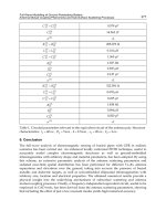
The parameters of OFHS and RFC570 are compared in this section, based on the previous
analysis. Handover parameters are given as in Table 1.
Parameter Value
T
HOP
1 ms
N
PAR-NAR
2 hops
T
DAD
800 ms
T
H
I
= T
IND
T
F
Table 1. Network Parameters
Fig. 9 shows total handover time of the RFC5270 and OFHS in term of frame durations for
predictive, semi-predictive and reactive modes according to Equations (6) to (9),
respectively. Handover latency variation in term of frame duration for all modes of the
Advanced Transmission Techniques in WiMAX
334
RFC5270 and the OFHS are depicted in Fig. 10. The numerical values are obtained from
Equations (10) to (13). Fig. 8 and Fig. 9 show that, the delay increases with the frame
duration increases. The reason is that the base station replies the received message at the
next frame because the current frame resource utilization is scheduled in advance.
Additionally the response time is lengthened as the frame duration increases. The OFHS
shows better total handover time and handover latency than RFC5270.
Fig. 9. Total Handover time versus Frame Duration
Fig. 10. Handover Latency versus Frame Duration
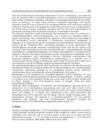
Usually in IEEE 802.16e, frame duration is considered as 5ms. In Fig. 11 total handover time
and handover latency of RFC5270 and OFHS in reactive, predictive and semi-predictive
modes for 5ms frame duration are illustrated. When frame duration is 5ms, OFHS decreases
total handover time to 47ms for predictive mode, and 90ms for semi-predictive and reactive
mode. The OFHS also reduces handover latency to 47ms for predictive mode, and 672ms for
Inter-Domain Handover in WiMAX Networks Using Optimized Fast Mobile IPv6
335
semi-predictive and reactive mode compare with RFC5270. The reason is that our scheme
needs less number of messages than that of the RFC5270 when performing handover, and
pre-established tunnel concept prepare a mechanism to reduce handover time. Also, the
additional anticipation time imposed by FMIPv6 that causes the handover execution start
earlier than planned is solved. In OFHS, occurrence probability of reactive mode is lower
than that of the RFC5270, because earlier handover preparation provides sufficient time for
the mobile node to receive FBack and drive predictive mode.
Fig. 11. Handover Latency for Ordinary Frame Duration (5ms)
6. Chapter summary
In this chapter an overview of inter-domain handover in WiMAX networks have been
presented. The previous solutions for applying FMIPv6 on IEEE 802.16e have long latency
that are not acceptable for real time services such as video streaming and voice over IP. In
order to reduce handover latency, an optimized fast IPv6 handover scheme (OFHS) have
been proposed. The OFHS combined cross layer design and cross function optimization to
achieve lower handover latency. A pre-established multi tunnelling concept and a buffered
routers mechanism have used to prepare seamless handover. The Layer 2 handover in
802.16e and layer 3 handover in FMIPv6 procedures are interleaved and the correlated
messages for both layers are blended and reconstructed, effectively.
The results show that OFHS reduces handover latency and packet losses, and increase
probability of predictive mode that has lower handover latency than reactive mode
compared with RFC5270. The OFHS reduces handover latency by 38.2% in predictive mode.
7. References
Chen, Y. and Hsieh, F. (2007). A Cross Layer Design for Handoff in 802.16e Network with
IPv6 Mobility, IEEE Communications Society subject matter experts, 2007
Han, Y.; Jang, H.; Choi, J.; Park, B. and McNair, J. (2007). A Cross-Layering Design forIPv6
Fast Handover Support in an IEEE 802.16e Wireless MAN, IEEE Network, Dec 2007.
IEEE 802.16e (2004). IEEE Standard for Local and Metropolitan Area Networks, part 16: Air
Interface for Fixed and Mobile Broadband Wireless Access Systems, IEEE
Advanced Transmission Techniques in WiMAX
336
IEEE 802.21 (2009). IEEE Standard for Local and metropolitan area networks- Part 21: Media
Independent Handover, IEEE
Jang, H. J.; Jee, J. ; Han, Y.H. ; Park, S.D. and Cha., J. (2008). Mobile IPv6 Fast Handovers
over IEEE 802.16e Networks, RFC5270 of Internet Engineering Task Force, Network
Working Group, Mar. 2008.
Johnson, D.; Perkins. C. and Arkko J. (2004). Mobility Support in IPv6, RFC 3775, Internet
Engineering Task Force
Koodli, R. (2005). Fast Handovers for Mobile IPv6, RFC 4068, Internet Engineering Task Force,
Network Working Group, July2005
Kwon, D. H.; Kim, Y. S.; Bae, K. J. and Suh, Y. J. (2005). Access router information protocol
with FMIPv6 for efficient handovers and their implementations, Globecom, pp.
3814-3819, 2005
Lee, D.H.; Kyamakya, K. and Umondi, J.P. (2006). Fast handover algorithm for IEEE 802.16e
Broadband Wireless Access System, In Wireless Pervasive Computing, 1st International
symposium, Jan. 2006
Lee, J.S.; Choi, S.Y. and Eom, Y.I. (2009). Fast Handover Scheme Using Temporary CoA in
Mobile WiMAX Systems, In 11th International Conference in Advanced Communication
Technology, ICACT 2009, pp. 1772–1776 (2009)
Liebsch, M.; Ed.; Singh, A.; Chaskar, H.; Funato, D. and Shim, E. (2005). Candidate Access
Router Discovery (CARD), RFC 4066, Internet Engineering Task Force, 2005.
Park, J.; Kwon, D.; Suh, Y. (2006). An Integrated Handover Scheme for Fast Mobile IPv6 over
IEEE 802.16e Systems, 2006
Perkins, C. (2002). IP Mobility Support for IPv4, RFC 3344, Network Working Group of Internet
Engineering Task Force, July 2005.
Seyyedoshohadaei, S.M.; Khatun S.; Mohd Ali, B.; Othman, M. and Anwar, F. (2009). An
Integrated Scheme to Improve Performance of Fast Mobile IPv6 Handover in IEEE
802.16e Network, proceeding of MICC 2009 Malaysian International Conference on
Communication, Kuala Lumpur, Malaysia, Des 2009
Seyyedoshohadaei, S.M.; Mohd Ali, B.; Othman, M. and Khatun S. (2011). Network Mobility
in IEEE 802.16e Network using Fast Mobile IPv6, proceeding of ASME International
Conference on Communication and Broadband Networking ICCBN 2011, pp.747-752,
Kuala Lumpur, Malaysia, Jun 2011
Thomson, S.; Narten, T. ; and Jinmei, T. (2007). IPv6 Stateless Address Auto configuration,
RFC 4862, Network Working Group of Internet Engineering Task Force, Sep 2007