Báo cáo hóa học: "Influence of structure of iron nanoparticles in aggregates on their magnetic properties" pptx
Bạn đang xem bản rút gọn của tài liệu. Xem và tải ngay bản đầy đủ của tài liệu tại đây (767.72 KB, 9 trang )
NANO EXPRESS Open Access
Influence of structure of iron nanoparticles in
aggregates on their magnetic properties
Dana Rosická
*
and Jan Šembera
Abstract
Zero-valent iron nanoparticles rapidly aggregate. One of the reasons is magnetic forces among the nanoparticles.
Magnetic field around particles is caused by composition of the particles. Their core is formed from zero-valent
iron, and shell is a layer of magnetite. The magnetic forces contribute to attractive forces among the nanoparticles
and that leads to increasing of aggregation of the nanoparticles. This effect is undesirable for decreasing of
remediation properties of iron particles and limited transport possibilities. The aggregation of iron nanop articles
was established for consequent processes: Brownian motion, sedimentation, velocity gradient of fluid around
particles and electrostatic forces. In our previous work, an introduction of influence of magnetic forces among
particles on the aggregation was presented. These forces have significant impact on the rate of aggregation. In this
article, a numerical computation of magnetic forces between an aggregate and a nanoparticle and between two
aggregates is shown. It is done for random position of nanoparticles in an aggregate and random or arranged
directions of magnetic polarizations and for structured aggregates with arranged vectors of polarizations. Statistical
computation by Monte Carlo is done, and range of dominant area of magnetic forces around particles is assessed.
Keywords: structure of aggregates, iron nanoparticles, aggregation , magnetic force s
1 Introduction
Zero-valen t iron nanoparti cles (nZVI) composed of iron
Fe
0
and i ts oxides are spherical particles with diameter
approximately 40 nm and with a large specific surface.
These particles are used for decontamination of ground-
water and soil and especially for decontamination of
organic pollutants such as halogenated hydrocarbons
[1]. Nanoparticles migrate through the soil and can
reach the contamination in situ. Properties of the nZVI
and remediation possibilities depend on methods of pro-
duction [2]. At the Technical University of Liberec,
experiments with iron nanoparticles TODA, produced
by the company Toda Kogyo Corp. [3], and with the
nanoparticles NANOFER, produced by the company
NANO IRON s.r.o. [4], are made. During a remedial
intervention, transport of the iron nanoparticles is slo-
wed down due to rapid aggregation of them. The rate of
aggregation increases with growing concentration of
particles in solution and with growing ionic strength of
the solution [5]. With the word particle we mean both
nanoparticles and aggregates. For preservation of the
transport properties, it is advisable to stabilize the parti-
cles. A lot of methods of stabilization were published
[6-10]. We simulate the transport of the iron nanoparti-
cles and that is why we examine the interactions among
them causing the aggregation. Models of aggregation of
small particles were published in many articles (e.g.,
[11-13]). They are mostly based on the publications [ 14]
and [ 15]. However, this generally used model is insuffi-
cient for our case. A surface charge established on the
surface of particles causes repulsive electrostatic forces
between them. The influence on the aggregation into
the known aggregation model was implemented in sub-
mitted article [Rosicka and Sembera (2009)]. The iron
particles corrode in the water, and t his process causes
change of the surface charge as well as the change of
the rate of agg regation [16]. Because the particles are
madefromiron,theyalsohavemagneticproperties,
which significantly affects the rate of aggregation
[2,17-20]. In the previous work, the influence of mag-
netic forces on rate of aggregation of iron particles was
assessed [21]. The magnetic forces have significant effect
on aggregation. Size of this effect is dependent on the
* Correspondence:
Technical University of Liberec, Institute of Novel Technologies and Applied
Informatics, Liberec, Czech Republic
Rosická and Šembera Nanoscale Research Letters 2011, 6:527
/>© 2011 Rosická and Šembera; licensee Springer. This is an Open Access article distribute d under the terms of the Creati ve Commons
Attribution License ( censes/by/2.0), which permits unrestricted use, di stribution, and reproduction in
any medium, provided the original wor k is properly cited.
magnitude of polarization of nanoparticles, their direc-
tions and distances among nanoparticles or aggregates.
We suppose same magnitude of vectors of polarization
of all nanoparticles. Hence, there is presented evaluation
of magnetic forces among particles depending only on
the structure of aggregates, respectively, on directions of
the vectors of polarization and distances between parti-
cles in this paper. In the f uture, the extended model of
the aggregation of iron nanoparticles will be included
into a solver of particle transport in gr oundwater. It
would allow to simulate the transport of iron nanoparti-
cles and to predict effciency of the remedial interven-
tion. That could be useful for proposal of optimal
remedial intervention which would enable to decontami-
nate an affected area effciently and economically.
2 Methods and models
2.1 Magnetic properties of nanoparticles
Because of the composition of nanoparticles, every
nanoparticle has nonzero vector of magnetization.
According to [19], the TODA iron nanoparticles with
diameter 40 nm have saturation magnetization
570 kA/m. This is value for composition of the nano-
particles 14.3% of Fe
0
and 85.7% of Fe
3
O
4
.Weuse
these data for our model. Therefore, we suppose the
same magnitude of vector of polarization for all nano-
particles. Our model of magnetic field around the iron
nanoparticle is based on the model of magnetic field
around a magnet described in [22]. The electromag-
netic potential in the point r near a permanent magnet
of volume V is equal to
φ(r) =
V
MR
R
3
dV
,
(1)
where M is the vector of magnetic polarization at the
point dV ,thevectorR is the difference between the
source of magnetic field dV and the point r, R is
the length of R.
Intensity of the magnetic field H can be subsequently
computed as
H
(
r
)
= −grad
(
φ
(
r
)).
(2)
Finally, the magnetic force between the source of the
intensity of magnetic field H and a permanent magnet
of volume
˜
V
with the vector of polarization M
0
at the
point r is equal to
F(r)=−
∫
˜
V
(M
0
· grad)H(r)dV
.
(3)
In prior work [21], we derived scalar potential of the
magnetic field around one homogeneous spherical iron
nanoparticle with radius a located at the point [0, 0, 0]:
φ(r)=M
2π
0
π
0
a
0
(x
3
− r
cos(θ ))r
2
sin(θ)
3
(x
2
1
+ x
2
2
+ x
2
3
− r
2
)
2
dr
dθ dϕ
,
(4)
where a is the radius of the nanoparticle, and [x
1
, x
2
, x
3
]
are the coordinates of the point r. Here, the direction of
the vector of polarization M is set to the direction x
3
, M is
the magnitude of the vector M.
From Equations 2 and 3, the analytical computation of
magnetic force between two iron nanoparticles can be
obtained. Since the nanoparticles aggregate, the magnetic
force between aggregates is required to derive. One aggre-
gate can be composed of millions of nanoparticles. It
would be time-consuming and very difficult to analytically
compute these forces. As a c onsequence, the forces are
computed numerically, either as a sum of magnetic forces
between every nanoparticle in one aggregate with every
nanoparticle in second aggregate or as one magnetic force
between two averaged aggregates. Averaged aggregate is a
big homogeneous particle with direction of polarization
M
A
computed as a vector sum of vectors of polarization of
all nanoparticles in the aggregate M
A
computed as an
average of magnitudes of all nanoparticles divided by
number of nanoparticles in the aggregate n:
M
A
=
n
i=1
M
i
n
.
(5)
2.2 Unstructured model of aggregates
The rate of aggregation depends on the vectors of polar-
izat ion of aggregating particles and on distance between
the particles. Rate of aggregation changes with changing
structure of ordering of nanoparticles in the aggregates.
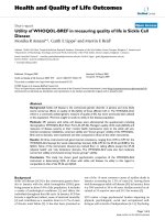
In this section, we imagine the model of structure of
aggregate as sphere with randomly located nanoparticles
in the aggregate either with random directions of polari-
zati on of every nanoparticle (Figure 1) or with the same
direction of polarization of all nanoparticles in the
aggregate (Figure 2).
2.3 Structured model of aggregates
In this section, we suppose structured ordering of nano-
particles in the aggregate. Vectors of polarizat ion of the
nanoparticles respect the structure. According to our
observations of behavior of spheri cal magnets, the mag-
nets create clusters with least energy. With sma ll num-
ber of magnets, the most created clusters are circles
formed by chains. We considered also other structured
models of aggregates - cubic and honeycomb. Directions
of vectors of polar ization of nanoparticles in these mod-
els of structured aggregates are shown in Figures 3, 4
and 5. On the basis of results in Section 3.2, it was
redundant to create more structured forms.
Rosická and Šembera Nanoscale Research Letters 2011, 6:527
/>Page 2 of 9
In the prior work [21], we used a term “effective range”.
It is range in which the magnetic field around one aggre-
gate attract an aggregate placed in the range. In this arti-
cle, we plot the influence of magnetic forces as one
number - limit distance. This dimension also expresses
the range of the magnetic forces among particles. Up to
this distance from the center of an aggregate, the attrac-
tive magnetic forces cause the aggregation of the aggre-
gate and a particle placed in the range. So in range larger
than the limit distance, other forces outweight the mag-
netic forces. For evaluation of this parameter, we co m-
pared the magnetic forces with a gravitation force
affected on the particle, according to scheme Figure 6.
Figure 1 Unstructured model of aggregate with random
directions of vectors of polarization of nanoparticles creating
the aggregate.
Figure 2 Unstructured model of aggregate with the same
direction of polarization of nanoparticles creating the
aggregate.
Figure 3 Structured model of aggregate in shape of circle with
directions of polarization respecting the shape.
Figure 4 Structured model of aggregate in shape of cube with
directions of polarization respecting the shape.
Rosická and Šembera Nanoscale Research Letters 2011, 6:527
/>Page 3 of 9
3 Results and discussion
3.1 Unstructured model of aggregates
3.1.1 Random directions of polarization of nanoparticles in
aggregates
Unstructured model of ordering of nanoparticles in an
aggre gate has been computed by averaging and by sum-
mation of magnetic forces between every nanoparticle in
first aggregate and every nanoparticle in second aggre-
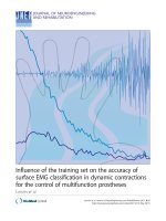
gate. In Figure 7, the comparison of averaging and sum-
mation is plotted in 2D for interactions between one
nanoparticle and an aggregate. Comparison can be done
by comparing of limit distances or effective range of
magnetic field around the particle.
The limit distance estimated by averaging decreases
more rapidly with growing aggregate than properly
computed magnetic forces. It means that for large
aggregates the averaging cannot be done, for the case
of attached particles. There is a lot of nanoparticles in
the big aggregate, and nanoparticles closer to the other
particle have larger influence on the magnetic force
between the aggregate and the examining nanoparticle.
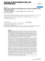
Comparison of averaged magnetic forces and summed
magnetic forces for attached particles is done in Table
1.TheplotteddatacanbeseenintheFigure8.How-
ever, in long distance between the particle and an
aggregate, the difference between averaging and sum-
mation is insignificant. The distances between nano-
particles in examined aggregate are negligible in
comparison with distance between the aggregate and
examined nanoparticle, as you can see in the Table 2
and in t he Figure 9. These data are computed for dis-
tance between particles of 1000 multiply of radius of
the aggregate.
You can also see the results for magnetic forces
between two interacting aggregates (Figure 10). The
computations are done by the averaging and the summa-
tion again. The conclusion is the same as for the case of
interacting aggregate with nanoparticle. In the case of
long distances a mong particles, computing by averaging
can be used. In the case of sh ort distances, the time-con-
suming computation by summation has to be done.
On the basis of known concentration of particles, we are
able to estimate the approximate distances among parti-
cles and to choose the right model of computation of mag-
netic forces and limit distances among the particles.
Figure 5 Structured mod el of aggre gate in shape of hexagon
with directions of polarization respecting the shape.
Figure 6 Comparing of attractive magnetic force and
counteracting gravitation force.
Rosická and Šembera Nanoscale Research Letters 2011, 6:527
/>Page 4 of 9
Figure 7 Graph of limit distances of interacting aggregate with one nanoparticle. Solid line represents attractive magnetic force between
an aggregate and a nanoparticle on which gravitation force effects. The dashed lines represent attractive magnetic force between a
nanoparticle attracting an aggregate. Square marks represent data computed by averaging, triangle marks stand for sum of magnetic forces of a
nanoparticle and all nanoparticles in an aggregate.
Table 1 Table of magnitudes of magnetic forces between interacting nanoparticle and aggregate
i Averaged F
mg
Deviation Summed F
mg
Deviation
1 1.4·10
-9
2.5·10
-9
6.3·10
-9
1.1·10
-9
10 4.4·10
-10
1.9·10
-10
6.3·10
-9
8.4·10
-9
100 7.2·10
-11
2.7·10
-11
4.6·10
-9
5.4·10
-9
1,000 1.1·10
-11
3.0·10
-12
7.4·10
-8
1.1·10
-7
10,000 1.9·10
-12
6.0·10
-13
5.9·10
-8
7.0·10
-8
1,000,000 2.8·10
-13
1.1·10
-13
8.7·10
-9
1.0·10
-8
1,000,000 5.4·10
-14
2.2·10
-14
3.0·10
-8
4.9·10
-8
Symbol i stands for number of nanoparticles in the aggregate. Averaged F
mg
is the magnetic force between the nanoparticle and an aggregate with av eraged
vectors of polarizations and destinations of nanoparticles in the aggregate. Summed F
mg
is magnetic force between the nanoparticle and the aggregate
computed by summation of magnetic forces between the nanoparticle and all the nanoparticles in the aggregate. Symbol Deviation stands for averaged value of
absolute deviations of data points from their mean value
Rosická and Šembera Nanoscale Research Letters 2011, 6:527
/>Page 5 of 9
3.1.2 The same directions of polarization of all
nanoparticles in aggregates
We examined structure of aggregates in which vectors
of polarization of all nanoparticles were the same in
magnitude and direction, distribution of nanoparticles in
the aggregate was unstructured. Comparison of limit
distances for unstructured model with random direc-
tions of polarization of nanoparticles in the aggregate
and for structured model with the same directions of
polarization is shown in Figure 11.
Figure 8 Graph of magnitude of magnetic force between one nanoparticle and an aggregate. Particles are attached to each other what
means that the distance between particles is equal to the sum of radii of both particles. The triangle marks represent data computed by
averaging of the positions, directions, and magnitudes of vectors of polarization of all nanoparticles in the examined aggregate. The magnetic
force is then computed between the nanoparticle and the averaged aggregate. The squared marks represent data computed by summation of
all interactions between the examined nanoparticle and every nanoparticle from the examined aggregate. Every nanoparticle has random
position and direction of vector of polarization. The particles are attached to each other, otherwise distance between the particles is the sum of
radii of particles.
Table 2 Table of magnitudes of magnetic forces between interacting nanoparticle and aggregate
i Averaged F
mg
Deviation Summed F
mg
Deviation
1 2.0·10
-20
1.0·10
-20
3.1·10
-20
5.5·10
-21
10 3.3·10
-21
2.3·10
-21
6.5·10
-21
4.0·10
-21
100 4.7·10
-22
2.8·10
-22
5.9·10
-22
2.2·10
-22
1,000 4.7·10
-23
1.7·10
-23
5.1·10
-23
3.0·10
-23
10,000 7.9·10
-24
4.0·10
-24
1.5·10
-23
8.5·10
-24
1,000,000 1.1·10
-24
5.6·10
-25
1.5·10
-24
1.1·10
-24
1,000,000 1.4·10
-25
7.1·10
-26
4.1·10
-25
2.0·10
-25
Symbol i stands for number of nanoparticles in the aggregate. Averaged F
mg
is the magnetic force between the nanoparticle and an aggregate with av eraged
vectors of polarizations and destinations of nanoparticles in the aggregate. Summed F
mg
is magnetic force between the nanoparticle and the aggregate
computed by summation of magnetic forces between the nanoparticle and all the nanoparticles in the aggregate. Symbol Deviation stands for averaged value of
absolute deviations of data points from their mean value. Distance between the nanoparticle and the aggregate is one thousand multiply of radius of the
aggregate
Rosická and Šembera Nanoscale Research Letters 2011, 6:527
/>Page 6 of 9
Figure 9 Graph of magnitude of magnetic force between one nanoparticle and an aggregate. Particles are in distance to each other of one
thousand multiple of the radius of examined aggregate. The triangle marks represent data computed by averaging of the positions, directions, and
magnitudes of vectors of polarization of all nanoparticles in the examined aggregate. The magnetic force is then computed between the
nanoparticle and the averaged aggregate. The squared marks represent data computed by summation of all interactions between the examined
nanoparticle and every nanoparticle from the examined aggregate. Every nanoparticle has random position and direction of vector of polarization.
Figure 10 Graph of limit distances of two interacting aggregates. Crosses represent limit distances computed by averaging of magnetic
forces. Squares stand for sum of magnetic forces of every nanoparticle from one aggregate and every nanoparticle in second aggregate. On the
left side of the graph, gravitation force effects on the smaller aggregate, on the right side, gravitation force effects on the bigger aggregate.
Rosická and Šembera Nanoscale Research Letters 2011, 6:527
/>Page 7 of 9
3.2 Structured model of aggregates
Further we examined model of structure of aggregates
in which nanoparticles creating the aggregate are dis-
tributed to a structure and vectors o f polarization
respect the structure. According to our observations of
behavior of spherical magnets, the magnets create clus-
ters with less energy in which vectors of polarization
subtract one another and final vector of polarization
approaches to zero. Consequently, in the c ase of struc-
tured ordering of nanoparticles, the magnetic forces
among the particles have not any influence on the
aggregation of particles. In the following table, magni-
tude of magnetic force between a nanoparticle and a
cubic aggregate attached to each other is prese nted.
Directions of polarization of nanoparticles in the aggre-
gate are set according to the Figure 4. Results show that
the magnetic force between structured particles
approaches to zero. Results of cubic structure are visible
in Table 3.
Even though the distance between the particles is the
smallest possible, the magnetic forces between the parti-
cles are negligible in comparison with gravitation forces.
For structured aggregates with polarization of nanoparti-
cles respecting the structure, the magnetic forces have
insignificant influence on the rate o f aggregation of the
particles.
4 Conclusion
We examined the influence of structure of nanoparticles
in aggregates on the resulting magnetic field around the
aggregates. The comparing parameter was size of mag-
netic forces among particles and the limit distance.
Figure 11 Graph of limit distances of interacting aggregate and nanoparticle representing comparison of the same and random
polarization of nanoparticles in the aggregate. Square marks represent the data of interaction between the nanoparticle and the aggregate
with random directions of polarization of nanoparticles in the aggregate. Triangle marks represent the data of interaction between the
nanoparticle and the aggregate with the same direction of polarization of nanoparticles in the aggregate. Both the random and the same
structured aggregates interactions were computed by summation.
Rosická and Šembera Nanoscale Research Letters 2011, 6:527
/>Page 8 of 9
According to these two connected parameters, we are
able to estimate the degree of influence of the magnetic
forces on rate of aggregation of partic les. We analyzed
magnetic properties of unstructured aggregates with
randomly distributed nanoparticles with random direc-
tion of polarization in the aggregates and of structured
model of aggregates with orderly distributed nanoparti-
cles and with arranged directions of pola riza tion. In the
case of structure d model, resulting magnetic f orces
approach to zero. Since we suppose that magnetic field
of iron particles has significant influence on the rate of
aggregation [19], the structured model is not sufficient.
Hence, we assume damaged structure of aggregates. In
our future work, the unstructured model will be com-
pared with experimental data of aggregation of iron
particles.
Acknowledgements
This result was realized under the state subsidy of the Czech Republic within
the research and development project “Advanced Remedial Technologies
and Processes Centre” 1M0554–Programme of Research Centres supported
by Ministry of Education and within the research project FR-TI1/456
“Development and implementation of the tools additively modulatin g soil
and water bioremediation"–Programme MPO-TIP supported by Ministry of
Industry and Trade.
Authors’ contributions
DR carried out the study of influence of structure of nanoparticles in
aggregates and drafted the manuscript. JŠ contributed to conception of the
study and to interpretation of data, and revised the manuscript. Both
authors read and approved the final manuscript.
Competing interests
The authors declare that they have no competing interests.
Received: 19 May 2011 Accepted: 14 September 2011
Published: 14 September 2011
References
1. Zhang W-X: Nanoscale iron particles for environmental remediation: an
overview. J Nanopart Res 2003, 5:323-332.
2. Li L, Fan M, Brown RC, Van Leeuwen J(H), Wang J, Wang W, Song Y,
Zhang P: Synthesis, properties, and environmental applications of
nanoscale iron-based materials. Rev Crit Rev Env Sci Technol 2006,
36:405-431.
3. Nurmi JT, Tratnyek PG, Sarathy V, Baer DR, Amonette JE, Pecher K, Wang C,
Linehan JC, Matson DW, Penn RL, Driessen MD: Characterization and
properties of metallic iron nanoparticles: spectroscopy, electrochemistry
and kinetics. Environ Sci Technol 2005, 39(5):1221-1230.
4. Filip J, Zboril R, Schneeweiss O, Zeman J, Cernik M, Kvapil P, Otyepka M:
Environmental applications of chemically pure natural ferrihydrite.
Environ Sci Technol 2007, 41:4367-4374.
5. Saleh N, Kim H-J, Phenrat T, Matyjaszewski K, Tilton RD, Lowry GV: Ionic
strength and composition affect the mobility of surface-modified Fe
0
nanoparticles in water-saturated sand columns. Environ Sci Technol 2008,
42(9):3349-3355.
6. Johnson RL, Johnson GO, Nurmi JT, Tratnyek PG: Natural organic matter
enhanced mobility of nano zerovalent Iron. Environ Sci Technol 2009,
43(14):5455-5460.
7. Kanel SR, Grenche J-M, Choi H: Arsenic(V) removal from ground-water
using nanoScale zero-valent iron as a colloidal reactive barrier material.
Environ Sci Technol 2006, 40(6):2045-2050.
8. Tiraferri A, Chen KL, Sethi R, Elimelech M: Reduced aggregation and
sedimentation of zero-valent iron nanoparticles in the presence of guar
gum. J Colloid Interface Sci 2008, 324:71-79.
9. Kanel SR, Manning B, Charlet L, Choi H: Removal of Arsenic(III) from
groundwater by nano scale zero-valent iron. Environ Sci Technol 2005,
39(5):1291-1298.
10. Song H, Carraway ER: Reduction of chlorinated methanes by nano-sized
zero-valent iron. Kinetics, pathways, and effect of reaction conditions.
Environ Eng Sci 2006, 23(2):272-284.
11. Buffle J, Van Leeuwen H, Eds: Environmental Particles Lewis Publishers 2,
Boca Raton FL; 1993, 353-360.
12. Somasundaran P, Runkana V: Modeling flocculation of colloidal mineral
suspensions using population balances. Int J Min Process 2003, 72:33-55.
13. Garrick S, Zachariah M, Lehtinen K: Modeling and simulation of
nanoparticle coagulation in high reynolds number incompressible flows.
Proceeding of the National Conference of the Combustion Institute 25-27 2001;
Oakland .
14. Thomas B, Camp R: Velocity gradients and internal work in fluid motion.
J Boston Soc Civ Engi 1943, 30:4.
15. Smoluchowski MV: Test of a mathematical theory of coagulation kinetics
of colloid solutions [in German]. Zeitschrift F Physik Chemie 1916,
XCII:129-168.
16. Reardon EJ, Fagan R, Vogan JL, Przepiora A: Anaerobic corrosion reaction
kinetics of nanosized iron. Environ Sci Technol 2008, 42(7):2420-2425.
17. Horák D, Petrovský E, Kapička A, Frederichs T: Synthesis and
characterization of magnetic poly(glycidyl methacrylate) microspheres. J
Magn Magn Mater 2007, 311:500-506.
18. Masheva V, Grigorova M, Nihtianova D, Schmidt JE, Mikhov M:
Magnetization processes of small γ-Fe
2
O
3
particles in non-magnetic
matrix. Phys D Appl Phys 1999, 32:1595-1599.
19. Phenrat T, Saleh N, Sirk K, Tilton RD, Lowry GV: Aggregation and
sedimentation of aqueous nanoscale zerovalent iron dispersions. Environ
Sci Technol 2007, 41(1):284-290.
20. Zhang LY, Wang J, Wei LM, Liu P, Wei H, Zhang YF: Synthesis of Ni
nanowires via a hydrazine reduction route in aqueous ethanol solutions
assisted by external magnetic fields. Nano-Micro Lett 2009, 1:49-52.
21. Rosická D, Šembera J: Assessment of influence of magnetic forces on
aggregation of zero-valent iron nanoparticles. Nanoscale Res Lett 2010.
22. Votrubík V: Theory of the Electromagnetic Field, [in Czech] Praha:
Czechoslovak Academy of Science Publication; 1958.
doi:10.1186/1556-276X-6-527
Cite this article as: Rosická and Šembera: Influence of structure of iron
nanoparticles in aggregates on their magnetic properties. Nanoscale
Research Letters 2011 6:527.
Table 3 Table of magnetic forces between one
nanoparticle and cubic aggregate
i|F
mg
| |F
g
|
1 2.4·10
-38
2.0·10
-18
8 4.1·10
-38
1.6·10
-17
125 6.6·10
-40
2.5·10
-16
1,000 7.7·10
-41
2.0·10
-15
10,648 8.4·10
-42
2.2·10
-14
97,336 5.7·10
-42
2.0·10
-13
1,000,000 5.0·10
-42
2.0·10
-12
The particles are attached to each other. Symbol i stands for numbe r of
nanoparticles in the cubic aggregate, |F
mg
| is magnitude of magnetic force
between nanoparticle and the aggregate, and |F
g
| stands for magnitude of
gravitation force between nanoparticle and the aggregate
Rosická and Šembera Nanoscale Research Letters 2011, 6:527
/>Page 9 of 9