Báo cáo hóa học: " Frequency domain equalization space-time block-coded CDMA transmission system" pdf
Bạn đang xem bản rút gọn của tài liệu. Xem và tải ngay bản đầy đủ của tài liệu tại đây (555.47 KB, 14 trang )
RESEARCH Open Access
Frequency domain equalization space-time
block-coded CDMA transmission system
César Augusto Medina
*
and Raimundo Sampaio-Neto
Abstract
In this work we propose a space-time block-coded (STBF) CDMA transmission system suitable for use with
frequency domain equali zation (FDE) algorithms. We illustrate the FDE by implementing the maximal ratio
combining, the zero forcing and the minimum mean squared error single user detection algorithms. A diversity
gain analysis is developed and some interesting results are pointed out. It is shown through compu ter simulations
that the proposed transmission system exhibits good performance in terms of bit error rate when compared to
previously proposed STB C CDMA transmission systems.
Keywords: frequency domain equalization (FDE), space-time block-codes (STBC), single carrier CDMA transmission
systems, multicarrier CDMA transmission systems
1 Introduction
Space-time block-codes (STBC) schemes have emerged
as a powerful transmit diversity technique to combat
fading in wireless communications. One of the most
successful space-time coding scheme was first proposed
by Alamouti [1] for the case of two transmit and multi-
ple receive antennas. Further developments for more
than two transmit antennas were later reported on [2,3],
and it was shown that the Alamouti’s scheme is the only
existing complex orthogonal design, with full rate, full
diversity and minimal delay. STBC was applied for
direct-sequence code division multiple access (DS-
CDMA) transmissi on system in [4,5]. All the aforemen-
tioned systems [1,5], assume flat-fading channels and
suffer performance degradation in frequency-selective
channels. Some STBC schemes to deal with frequency
selectiv ity have been proposed for orthogonal frequency
division multiplexing (OFDM) [6], single-carrier (SC)
time-domain equalization [7] and single-carrier fre-
quency-domain equalization (SC-FDE) systems [8,9].
The complexity and performance of SC-FDE systems
are comparable to that of OFDM systems while avoiding
drawbacks associated with multicarrier (MC) implemen-
tation. On the other hand, SC systems cannot certainly
offer the same flexibility as OFDM in the management
of bandwidth and energy resources [10] and FDE does
not represent an optimal solution to signal detection
over frequency-selective channels due to intersymbol
interference (ISI). In [11], adaptive algorithms to miti-
gate ISI effects for frequency domain equalization (FDE)
in frequency-selective channels were proposed.
STBC CDMA-based transceivers for frequency-selective
channels have been studied in [12-16], using a structure
similar to the one proposed in [4,5] for the case of flat-
fading channels. A different structure for STBC single
carrier CDMA transmission system based on chip-inter-
leaved block-spread (CIBS) CDMA [17] was proposed in
[18]. The structure in [18], though promising excellent
performance, incurs in a relatively high computational
complexity to update the equalizer coefficients [19]. In
[20], time-reversal is used to provide FDE capabilities to
STBC single carrier CDMA transmission system.
In this work a structure for FDE STBC CDMA-based
transmission system is proposed. In this structure, trans-
mit symbols are spread in a symbol-by-symbol basis and
the self-interference in the receiver is avoided by the use
of permutation matrices [21,22] in the transceiver, which
also allow us to decode each transmit symbol separately.
We present the propose d transmiss ion system in a gen-
eral framework, which allows us to perform an unified
analysis and to present a fair comparison between com-
monly used CDMA-based block transmission systems.
Also, as we show through computer simulations, FDE
* Correspondence:
Centro de Estudos em Telecomunicações (CETUC), Pontifícia Universidade
Católica do Rio de Janeiro (PUC-Rio), Rio de Janeiro, RJ, Brazil
Medina and Sampaio-Neto EURASIP Journal on Wireless Communications and
Networking 2011, 2011:80
/>© 2011 Medina and Sampaio- Neto; licensee Springer. This is an Open Access art icle distribute d under the terms of the Creative
Commons At tribution Licen se (http:/ /creativecommons.org/licenses/by/2.0), which permi ts unrestricted use, distribution, and
reproduction in any medium, provided the original w ork is properly cited.
algorithms used with single user detection results in a
simple receiver design with good performance in terms
of bit error rate (BER) when compared with previously
proposed STBC CDMA transmission systems. A diversity
gain analysis of the proposed transmission system is per-
formed providing interest results.
This paper is organized as follows: Section 2
describes the baseband system model, addressing the
definitions and properties of the employed matrices. In
Section 3 we present and point out some properties
of the receiver design, while in Section 4 different
approaches for FDE are applied in the proposed
scheme. Section 5 presentstheresultsobtained
through computer simulations and Section 6 gives
some conclusions. A diversity and coding gain analysis
is included as an appendix.
Notation. In what follows, I
k
represents a k × k identity
matrix, 0
m×n
,anm × n null matrix, (·)
T
, (·)
H
, (·)* and (·)
†
denote transpose, Hermitian transpose, complex conju-
gated and Moore-Penrose matrix inverse, respectively, ⊗
is t he Kronecker product, diag(x) is a diagonal matrix
with the components of x as its nonzero elements, rank
(·) is the rank of a matrix, det(·) denotes determinant,
the operator E [·] stands for ensemble average and ℂ(ℝ)
represents the field of the complex (real) numbers.
2 System model
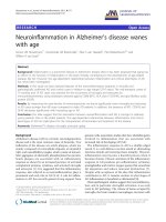
Consider the discrete-time equivalent baseband model
of a synchronous downlink STBC CDMA system shown
in Figure 1 (for convenience only one user is shown).
For simplicity, in this paper we will focus on the case
of two transmit antennas and one receive antenna,
although this schema could be easily extended to config-
urations with more receive antennas, provided an
appropriate combiner, such as maximal ratio combiner
(MRC), would be used.
In the proposed system each of the K users transmits
symbols s
k
(i) Î ℂ, which are first spread by the M-chip
spreading code c
k
Î ℂ
M
,||c
k
||
2
= 1, and then grouped
in vectors c
k
s
k
(i) of size M. It is assumed that symbols s
k
(i) are drawn from some constellation with zero mean
and unit average symbol energy and they are indepen-
dent and identically distributed (i.i.d.).
Then, the spread symbols are li nearly precoded by the
matrix G Î ℂ
M×M
and fed into the Alamouti-based
space-time encoder [1] to get the space-time symbol
S
k
(i)=
¯
s
k
(2i) P
tx
¯
s
∗
k
(2i +1)
¯
s
k
(2i +1) −P
tx
¯
s
∗
k
(2i)
(1)
where
¯
s
k
(
i
)
= Gc
k
s
k
(
i
)
, G represents an arbitrary linear
operation used to combat deleterious channel effects
and to simplify equalizer designs. P
tx
Î ℝ
M×M
is a per-
mutation matrix whose design depends on the overall
system and it is used to decouple, in the receiver, the
transmitted symbols, as we will show later.
It should be noted that a guard interval is necessary to
avoid interblock interference (IBI) in the received signal.
The guard interval insertion is performed by the matrix
T Î ℝ
P×M
,whereP = M + L
gi
and L
gi
is the length of
the guar d interval. For the most commonly used guard
intervals, cyclic prefix (CP) and zero padding (ZP), the
matrix T is defined as [23]:
T
cp
=
0
L
gi
×(M−L
gi
)
|I
L
gi
I
M
T
zp
=
I
M
0
L
g
i
×M
.
The frequency-selective channel from the jth (j =1,2)
transmission antenna to the re ceiver can be modeled
✲ ✲ ✲
✲
✲
✲
✲
❄
✻
♠
♠
❄ ❄
♠
✠❘
✲
r(2i)
r(2i +1)
STACK
F
Q
Rr(2i)
F
Q
P
rx
Rr
∗
(2i +1)
✛
✛
U
H
(2i)
y
1
(i)
y
2
(i)
z
0
(i)
z
1
(i)
✛
✛
✛
✛
✛
✛
✛
✛
✛
Other users
Other users
n(2i)
h
0
(2i)
h
1
(2i)
T
T
Space-Time
S
k
(i)
encoder
s
k
(2i)
s
k
(2i +1)
c
k
G
s
k
(2i)
s
k
(2i +1)
Q(2i)
Q(2i)
v
H
k
v
H
k
ˆs
k
(2i)
ˆs
k
(2i +1)
FDE a nd Symbol Detection
Figure 1 STBC CDMA transmission system.
Medina and Sampaio-Neto EURASIP Journal on Wireless Communications and
Networking 2011, 2011:80
/>Page 2 of 14
using a finite-impulse response (FIR) filter with L taps,
whose gains are samples, taken at the chip rate, of the
equivalent baseband complex channe l impulse response.
Assuming that during two symbol periods the impulse
response of both channels remain constant, that is, h
j
(2i)=h
j
(2i +1)=[h
j,0
(2i) h
j,L-1
(2i)]
T
, E [||h
j
(2i)||
2
]=
1, the transmission through the frequency-selective
MIMO channel can be represented by a P × P lower tri-
angular T oeplitz convolution matrix H
j
(2i), whose first
column is [h
j,0
(2i) h
j,L-1
(2i) 0 0]
T
.
Asweassumeadownlinkscenario,wheretheusers
experience the same channel condition, the received sig-
nal collected over two consecutive symbol periods is
represented by the two P-dimensional vectors:
r(2i)=H
0
(2i)T
¯
s(2i)
+ H
1
(2i)T
¯
s(2i +1)+n(2i)+η(2i
)
r(2i +1) = H
0
(2i)TP
2tx
¯
s
∗
(2i +1)
− H
1
(2i)TP
tx
¯
s
∗
(2i)+n(2i +1)
+ η
(
2i +1
)
(2)
where n(i) is a complex white Gaussian noise vector
with zero mean and covariance matrix E [n(i)n
H
( i)] =
N
0
I
P
, N
0
is the noise spectral density, h(i) denotes the
IBI present in non-ZP systems (h( i)=0 in ZP systems)
and
¯
s(i)=
˜
E
s
K
k
=1
ρ
k
¯
s
k
(i)=
˜
E
s
GCρs(i
)
(3)
where
˜
E
s
=
(
E
1
+ ···+ E
K
)
/
K
is the mean received
energy, with E
k
being the energy of the k user signal,
ρ
k
=
E
k
/2
˜
E
s
, r = diag(r
1
; r
K
), C =[c
1
··· c
K
], s(i)=
[s
1
(i) s
K
(i)]
T
.
If CP is used as guard inter val at the transmitter, the
receiver must remove the guard interval from the
received signal to eliminate IBI. If ZP is used at the
transmitter the IBI is null, and then, the gua rd interval
removal is not necessary. This operation is represented
by the matrix R, where
R
= R
cp
=[0
M×L
g
i
|I
M
]
for CP sys-
tems and R = R
zp
= I
P
for ZP systems.
Finally, the space-time decoding is performed by first
stacking the received signals o ver t wo consecutive sym-
bol periods, as:
y(i )=
F
Q
Rr(2i)
F
Q
P
rx
Rr
∗
(2i +1)
(4)
where Q = M for CP systems and Q = P for ZP case,
P
rx
Î ℝ
Q×Q
is a permutation matrix whose design
depends on the overall system, and in conjunction with
P
tx
it is used to perform symbol decoupling in the
received STBC symbols, as will be detailed below. F
Q
is a
Q×Qmatrix that implements a Q-point discrete Fourier
transform, normalized such that,
F
H
Q
F
Q
= F
Q
F
H
Q
= I
Q
.
Using (2) and (3), we can rewrite (4) as
y(i )=
f
0
(H
0
)s(2i)+f
0
(H
1
)s(2i +1)
f
1
(H
0
)s(2i +1)− f
1
(H
1
)s(2i)
+
F
Q
Rn(2i)
F
Q
P
rx
Rn ∗ (2i +1)
¯
n
(
i
)
(5)
where
f
0
(H
j
)=
˜
E
s
F
Q
RH
j
(2i)TGC
ρ
(6)
f
1
(H
j
)=
˜
E
s
F
Q
P
rx
RH
∗
j
(2i)TP
tx
GCρ
.
(7)
Note that the term h(i) in (2), which acc ounts for IBI
in non-ZP guard interval syste ms, is removed by the
joint operation of matrices T and R. It should be
stressedthattheguardintervallengthmustbeatleast
the channel order in order to avoid IBI, i.e., L
gi
≥ L-1
[23].
The choice of ZP or CP as the guard interval is conve-
nient, since it allows us the use of the following well
known properties:
(p1) CP case: R
cp
H
j
(2i)T
cp
reduces to a circulant
matrix,
H
j
(2i
)
, of dimension M × M.
(p2) ZP case: R
zp
H
j
(2i)T
zp
is equivalent to
H
j
(2i)T
z
p
where
H
j
(2i
)
is a circulant matrix of dimension P × P.The
equivalence is due to R
zp
= I
P
and the structure of T
zp
.
(p3) A circulan t matrix
H
j
(2i
)
of dimension Q×Q,as
in (p1) and (p2), can be decomposed as
H
j
(2i)=F
H
Q
j
(2i)F
Q
and
H
H
j
(2i)=F
H
Q
∗
j
(2i)F
Q
,where
Λ
j
(2i) is a diagonal matrix whose entries are the fre-
quency response of the transmiss ion channel h
j
(2i), i.e.,
j
(2i)=diag(
˜
F
Q×L
h
j
(2i)
)
,where
˜
F
Q
×
L
is a Q × L
matrix formed with the first L columns of the matrix
that implements the (non-normalized) Q-point discrete
Fourier transform.
In order to decouple the transmitted symbols and to
provide FDE capabilities to the system, we choose P
tx
and P
rx
as in [21], where they are drawn from a set
{P
(n)
J
}
J−1
n=
0
,whereJ is the dimension of P. Each
P
(n
)
J
per-
forms a reverse cyclic shift that depends on n when
applied to a J×1 vector. This set of matrices has two
useful properties:
(p4) Pre- and post-multiplying a circulant matrix,
H
j
(2i)
,by
P
(n
)
J
yields
H
T
j
(2i
)
,i.e.,
P
(n)
J
H
j
(2i)P
(n)
J
= H
T
j
(2i
)
and
P
(
n
)
J
H
∗
j
(2i)P
(
n
)
J
= H
H
j
(2i
)
[21].
(p5)
T
z
p
P
(
0
)
M
= P
(
M
)
P
T
z
p
[22].
Medina and Sampaio-Neto EURASIP Journal on Wireless Communications and
Networking 2011, 2011:80
/>Page 3 of 14
Then, if for CP systems we choose
P
rx
= P
tx
= P
(
0
)
M
and
using (p1), (p4) and (p3) we get:
f
0
(H
j
)=
˜
E
s
j
(2i)F
M
GCρ =
˜
E
s
j
(2i)
V
(8)
f
1
(H
j
)=
˜
E
s
∗
j
(2i)F
M
GCρ =
˜
E
s
∗
j
(2i)
V
(9)
where V = F
M
GCr.
Inthesameway,forZPsystemswecanchoose
P
rx
= P
(
M
)
P
and
P
tx
= P
(
0
)
M
, then using (p2), (p5), (p4) and
(p3) we have:
f
0
(H
j
)=
˜
E
s
j
(2i)F
P
T
zp
GCρ =
˜
E
s
j
(2i)
V
(10)
f
1
(H
j
)=
˜
E
s
∗
j
(2i)F
P
T
zp
GCρ =
˜
E
s
∗
j
(2i)
V
(11)
where V = F
P
T
zp
GCr.
Now, using the results (8)-(11), the space-time
decoded vector in (5), can be expressed as
y(i )=
˜
E
s
0
(2i)
1
(2i)
−
∗
1
(2i)
∗
0
(2i)
(2i)
Vs(2i)
Vs(2i +1)
+
¯
n
(
i
)
(12)
where
j
(2i)=diag(
˜
F
Q×L
h
j
(2i)) (j =0,1
)
and V is
the Q × K matrix defined in connection with (8)-(11).
Note that the noise vector
¯
n
(
i
)
in (5) and (12) is still
Gaussian with zero mean and covariance matrix N
0
I
2Q
.
3 Re ceiver Design
Assuming that perfect channel estimation is performed
at the receiver, we can define an orthogonal matrix
U(2i)=(2i)(I
2
⊗
−1
0
1
(2i)
)
of dimension 2Q ×2Q,
where
01
(2i)=[
∗
0
(2i)
0
(2i)+
∗
1
(2i)
1
(2i)]
1/2
.
(13)
Then, U
H
(2i)Λ(2i)=I
2
⊗ Λ
01
(2i), and
z(i)=U
H
(2i)y( i)=
˜
E
s
01
(2i) 0
Q×Q
0
Q×Q
01
(2i)
·
·
Vs(2i)
Vs(2i +1)
+ U
H
(2i)
¯
n(i
)
(14)
thus, U(2i) decouples the received vector allowing s
(2i) and s(2i + 1) to be demodulated separately from:
z
0
(i)=
˜
E
s
01
(2i)Vs(2i)+
¯
n
0
(2i
)
z
1
(i)=
˜
E
s
01
(2i)Vs(2i +1)+
¯
n
1
(2i +1
)
(15)
where
U
H
(2i)
¯
n(i)=[
¯
n
T
0
(2i)
¯
n
T
1
(2i +1)]
T
.AsU(2i)is
an orthogonal matrix, it does not alter the statistical
properties of the noise vector
¯
n
(
i
)
.
With z
j
(i)(j = 0, 1), as in (15), symbol detection can
adopt different approaches as illustrated next.
3.1 Multiuser maximum likelihood (ML) detection
The optimal solution of the proposed system is to
jointly detect the transmitted symbol of the differ ent
users within the transmitted vector, based on the
received vector. Thus, the optimum receiver is a multiu-
ser (MU) maximum likelihood (ML) receiver, implemen-
ted, in this case, by the minimum distance receiver, such
that, for j =0,1:
ˆ
s(2i + j) = arg min
s
˜
E
s
01
(2i)Vs− z
j
(i)
2
.
(16)
As shown in the appendix, the maximum diversity
gain G
d
=2L, is attained fo r this receiver when ||Λ
01
(2i)
Ve||
2
≠ 0, ∀e ≠ 0. Then, a sufficient condition fo r maxi-
mum diversity gain, is to guarantee that, for any e ≠ 0,
at least L elements from Ve are different from zero.
Proof: In the following, we drop the time index to sim-
plify the notation. Let l
01,l
be the real and non-negative
lth element of the diagonal of Λ
01
and
e
l
the lth element
of Ve, then:
||
01
Ve||
2
=
Q−1
l
=
0
λ
2
01,l
|e
l
|
2
(17)
where
λ
2
01
,
l
= |λ
0,l
|
2
+ |λ
1,l
|
2
,withl
j,l
(j =0,1)being
the l-th element of
˜
F
Q×L
h
j
(j =0,1
)
.SincetheQ-points
discret e Fourier transform of a vector of size L can have
at most L - 1 zero elements, it then results that at most
L -1valuesofl
01,l
can be equa l to zero. Then, if
e
l
= V
e
has at least L elements differen t from zero, we
have that
Q−1
l=0
λ
2
01
,
l
|e
l
|
2
=0
and the maximum diver-
sity gain is achieved. ■
3.1.1 ZP systems
For the ZP systems, V = F
P
T
zp
GCr.Nowusing
Ve=
˜
F
P×M
e
0
,where
˜
F
P×M
= F
P
T
z
p
is P × M matrix
formed with the first M columns of F
P
and e
0
= GCre is a
M-dimensional vector, if the user codes are linearly inde-
pendent, and provided that G is non-singular, then GC is
full column rank and therefore e
0
≠ 0 for any e ≠ 0.Again,
since the P-points discrete Fourier transform of a
sequence of M points can have at most M - 1 zeros, then
˜
F
P×M
e
0
has at least P -(M -1)=L + 1 elements different
from zero, thus maximum diversity gain is achieved.
So, for ZP systems, the maximum diversity gain is
achieved independent of the choice of the user c odes,
Medina and Sampaio-Neto EURASIP Journal on Wireless Communications and
Networking 2011, 2011:80
/>Page 4 of 14
the precoding matrix and t he number of users on the
system, provided that GC is full column rank.
3.1.2 CP systems
For CP systems V = F
M
GCr, then, in general, we cannot
guarantee t hat the maximum diversity gain is achieved
by the system. However, proper choices of the precoding
matrix and s preading codes, can lead to full diversity
gain. For example, if F
M
GC is a Vandermonde matrix
(e.g.,
G = F
H
M
and the codes c
k
are columns of a Vander-
monde matrix
1
), and GC is full column rank, then for
any K dimensional vector e ≠ 0, Ve has at most K -1
zeroes, or equivalently, it has at least M - K + 1 ele-
ments different from zero. Then, maximum diversity
gain is achieved provided that K ≤ M - L +1.
3.2 Minimum mean squared error single user detection
Using z
j
(i)(j = 0, 1), from (15), the kth user minimum
mean squared error (MMSE) rec eiver for each symbol,
w
k,j
, is obtained by minimizing the mean-squared error
criterion
w
k,j
= arg min
w
E
|s
k
(2i + j) − w
H
z
j
(i)|
2
,
(18)
whose solution is given by [24]:
w
k,j
= R
−1
z
j
z
j
p
z
j
s
k
,
(19)
where
R
z
j
z
j
= E
z
j
(i)z
H
j
(i)
and
p
z
j
s
k
= E[z(i)s
∗
k
(2i + j)
]
.
Symbol detection is performed for j = 0, 1 as:
ˆ
s
k
(2i + j)=disc
w
H
k,j
z
j
(i)
(20)
where disc{n} returns the symbol constellation closer
to n.
From (15) is easy to conclude that
R
z
0
z
0
= R
z
1
z
1
=
˜
E
s
01
(2i)VV
H
H
0
1
(2i)+N
0
I
Q
(21)
and
p
z
0
s
k
= p
z
1
s
k
=
˜
E
s
01
(2i)v
k
,wherev
k
is the kth col-
umn of V. It follows that w
k,0
= w
k,1
.
As we assume downlink transmission, in practical
situations only the kth column of V is known to the kth
user receiver. Then, an iterative procedure, like the
recursive least squares (RLS) algorithm [24] or conju-
gated gradien t algorithm [ 25], must be used to compute
the desired solution (19).
4 Frequency domain equalization
From (15) one can see tha t FDE can be performed by
applying an one-tap chip-equalizer to each component
of the vectors z
j
( i)(j = 0, 1). Such operation is repre-
sented by the pre-multiplication of the vectors z
j
(i)(j =
0, 1) by a diagonal matrix Q(2i) Î ℂ
Q×Q
, whose ele-
ments are the weights of the one-tap chip-equalizer.
Symbol detection is then performed over the fre-
quency equalized and despread signal:
ˆ
s(2i + j)=disc
V
†
Q(2i)z
j
(i)
j =0,
1
(22)
where disc{n} is the vector whose components
are the symbols of the signal constellation close r to
the components of vector n and (·)
†
represent the
Moore-Penrose matrix inverse. In order to avoid high
computational complexity algorithms, it is desired to
have V
†
= V
H
, which is true, for example, if G is an
orthogonal matrix and the spreading codes are
orthogonal.
As in the downlink the receiver is only interested in
the kth user, symbol detection is performed as
ˆ
s
k
(2i + j)=disc
v
H
k
Q(2i)z
j
(i)
(23)
where v
k
is the kth colum n of V, and we assume that
V
†
= V
H
.
Now, let us consider the noiseless part of the d ecision
variable,
v
H
k
Q(2i)z
j
(i
)
. For the CP case we have
c
H
k
G
H
F
H
M
˜
I(2i)F
M
˜
I
CP
(
2i
)
GC s(2i + j
)
(24)
and for the ZP case
c
H
k
G
H
T
H
zp
F
H
P
˜
I(2i)F
P
I
ZP
(
2i
)
T
zp
GC s(2i + j
)
(25)
where
˜
I
(
2i
)
= Q
(
2i
)
01
(
2i
)
is a diagonal matrix. Note
that in general
˜
I(2i) = I
Q
, and thus
˜
I
CP
(2i)=F
H
M
˜
I(2i)F
M
and
˜
I
ZP
(2i)=F
H
P
˜
I(2i)F
P
are circulant matrices that
introduce code distortion and inter-chip interference in
the equalization process.
So, one can design the precoding matrix, G,inorder
to mitigate such undesir ed effects. Two simple
approachesarecommonlyused.Thefirstoneisto
choose the identity matrix as the precoding matrix,
resulting into the well-known single-carrier block trans-
mission systems. In both cases, CP and ZP systems, sin-
gle carrier modulation presents code distortion and
inter-chip interference, produced by the circulant matrix
˜
I
(
2i
)
.
The second approach is to choose
G = F
H
M
, leading the
so-called multicarrier block transmission systems. In
this case, for CP systems, the noisel ess decision variab le
(24) reduces to
c
H
k
˜
I(2i)Cs(2i + j
)
, that states the absence
of inter-chip interference (as
˜
I
(
2i
)
is a diagonal matrix),
however, code distortion is present.
We next consider the design of the one-tap equaliza-
tion matrix Q(2i)=diag(q
0
(2i), , q
Q
(2i)) following
standard approaches.
Medina and Sampaio-Neto EURASIP Journal on Wireless Communications and
Networking 2011, 2011:80
/>Page 5 of 14
4.1 MRC single user detection
This receiver weights each sub-channel by its respective
complex conjugate e quivalent sub-channel coefficient,
leading in the present case to
q
l
(2i)=λ
01,l
(2i)=
|λ
0,l
(2i)|
2
+ |λ
1,l
(2i)|
2
(26)
where l
01,l
(2i) is the real and non-negative lth element
of the diagona l of Λ
01
(2i)andl
j,l
(2i)(j =0,1)isthelth
element of
˜
F
Q×L
h
j
(2i
)
.
Whit this choice, Q(2i)=Λ
01
(2i)andthen
˜
I(2i)=
2
0
1
(2i
)
. Thus, this equalize the spreading code
distortion introduced by the transmission channel and
may enhance the multiple access interference (MAI).
4.2 Zero forcing (ZF) single-user receiver
Zero forcing applies channel inversion so that
Q(2i)=
−1
0
1
(2i
)
and
˜
I(2i)=I
Q
.Thus,thisequalizer
eliminates code distortion, and for the case of multicar-
rier with CP transmissions s ystems also removes the
inter-chip interference and can, therefore, eliminate
MAI (if user codes are orthogonal). The equalizer coeffi-
cients are chosen as
q
l
(2i)=
1
λ
01,l
(
2i
)
.
(27)
The main drawback of this equalizer is that when l
01,l
(2i) ≈ 0, the noise effects are enhanced.
4.3 MMSE single-user detection
The equalizat ion coefficient based on the MMSE criter-
ion for the proposed system results in [26]:
q
l
(2i)=
λ
01,l
(2i)
λ
2
01
,
l
(2i)+σ
2
(28)
where s
2
is the variance of the noise. We have
Q(2i)=(
2
0
1
(2i)+σ
2
I)
−1
01
(2i
)
and
˜
I(2i)=(
2
0
1
(2i)+σ
2
I)
−1
2
0
1
(2i
)
, thus, as with the MRC
this equalizer does not e liminatecodedistortion.How-
ever, it offers a good trade off between code distortion
reduction and noise enhancement.
5 Simulation results
We consider the downlink scenario of the proposed
STBC CDMA transmission system with two transmit
and one receive antenna. The data symbols are binary
phase-shift keying (BPSK) modulated and spreading by a
length M = 16 spreading code. The system is loaded
with K = 4 users and two types of guard intervals are
considered in co mbination with two different choices of
precoding matrix, G = I
M
and
G = F
H
M
,leadingtofour
different systems, as shown in Table 1 where MC stands
for multicarrier and SC for single carrier.
In all the experiments, we obtain the average bit-error
rate (BER) versus E
b
/N
0
(E
b
istheenergyperbitofthe
desired user) as the performance measure. In each
experiment we run 30, 000 Monte Carlo realizations,
with 2,000 symbols transmi tted per run. The trans-
mitted symbols are randomly generated and it is
assumed that the first 500 symbols are used as the train
sequence for the equalizers.
5.1 Performance of the transceiver
In the first experiment we compare two different transcei-
vers, the one proposed i n [4], adapted to the systems in
Table 1 as reported in [16], denoted as STBC in the fig-
ures, and the transceiver proposed in this work. In o rder
to allow a fair comparison between the transceivers, we
employ a MMSE type of receiver (see Section 3.2), with a
conjugated gradient [25] adaptive implementation. For
comparison p urposes, the performance o f a single user
MMSE type of receiver for a block CDMA-based system
with only one antenna at the transmitter and one antenna
at the receiver, denoted as SISO, is also presented.
The channel from each transmit anten na to the recei-
ver is modeled here as a time-variant FIR filter, with
coefficients given by h
j,l
(i)=p
j,l
a
j,l
(i)(j = 1, 2 and l =0,
1, 2, , L -1)wherea
j,l
(i)isobtainedwithClarke’s
model [27]. This procedure corresponds to the genera-
tion of independent sequences of correlated unit power
complex Gaussian random va riables
(E
|α
2
j,l
(i)|
=1
)
with the path weights p
j,l
normalized so that
L−1
l=0
|p
j
,l
|
2
=
1
. Here, the channel coefficients are kept
constant during two-symbol period and each cha nnel
has L = 4 transmission paths of equal weight, i.e., | p
j,l
|
2
=1/L, l = 0, 1, 2, 3. The guard interval length is L
gi
=3.
The results depend on the normalized Doppler fre-
quency (f
d
T), where f
d
is the Doppler frequency and T is
the duration of two symbols. A value f
d
T =0.001was
assumed in all simulations. The systems use H adamard
codes of length M = 16. In each run, the user codes
were randomly chosen, b ut we avoid the use of the first
and second Hadamard code, which corresponds to the
first and second column of the Hadamard matrix.
Table 1 Transmission system considered
Transmission System GTR
MC CDMA CP
F
H
M
T
cp
R
cp
MC CDMA ZP
F
H
M
T
zp
I
P
SC CDMA CP I
M
T
cp
R
cp
SC CDMA ZP I
M
T
zp
I
P
Medina and Sampaio-Neto EURASIP Journal on Wireless Communications and
Networking 2011, 2011:80
/>Page 6 of 14
For the proposed transceiver, before the MMSE single
user detection stage, decoupling of the received vector
must be performed, as shown in (14), (15). For this pur-
pose, two channel estimates were used. The first one is
an ideally estimated channel, denoted as Proposed in
the figures, while the se cond one, denoted ‘Proposed w/
Error’ in the figures, is a noisy channel estimate,
ˆ
h
j
(2i)=h
j
(2i)+ζ
j
(2i
)
,whereζ
j
(2i) is a complex white
Gaussian noise vector with zero mean and covariance
matrix
E
ζ
j
(2i)ζ
H
j
(2i)
= σ
2
ζ
I
L
. In this experiment, we
set the mean squared relative error of the channel esti-
mate to 10 dB. Note, that the conjugated gradient algo-
rithm that follows the decoupling does not need the
channel knowledge to reach the MMSE solution.
Figures 2 and 3 show the BER results versus E
b
/N
0
for
CP and ZP systems, respectively. As can be noted, for
multicarrier systems, the proposed receiver performs
better than the STBC receiver, even in the presence of
channel estimatio n errors. When comparing multicarrier
systems versus single carrier systems, we observe the
BER floor for single carrier systems. This is due, in part,
to the better recovering of the spreading codes per-
formed by the multicarrier systems.
In the case of SC CDMA ZP s ystem of the Figure 3,
it was observed that the receiver restored some of the
orthogonality between user codes, resulting in good
signal to interference-plus-noise ratio, which in turn
results in enhanced BER. For the case of SC CDMA
CP of the Figure 2, the same receiver could not restore
the orthogonality b etween user codes, resulting in poor
signal to interference-plus-noise ratio and then in
worst BER.
5.2 Performance of FDE algorithms
In this experiment we compare different FDE algorithms
for t he proposed structure (see Section 4): MRC single
user receiver (FDE MRC), zero forcing single user recei-
ver (FDE ZF), and MMSE single user receiver (FDE
MMSE). We use the same time-variant channel used in
the first experiment and we assume that the channel
was perfectly estimated. The system uses Hadamard
codes of length M = 16 and were chosen as in the first
experiment. Results for a matched filter single user
algorithm (MF) are also shown in the figures. In this
algorithm the receiver filter is matched to the user
spreading code at the receiver.
Figures 4 and 5 show the BER results versus E
b
/N
0
for
CP an d ZP systems, respectively. As expected, the FDE
MMSE receiver outperforms the FDE ZF, the FDE MRC
and the MF receivers. Furthermore, all these receivers
have similar computational complexity.
Also note that for FDE ZF and FDE MMSE receivers,
multicarrier systems perform better than for single car-
rier systems due to the small and e ven null inter-chip
interference of multicarrier systems with FDE, as stated
before in Section 4.
5.3 Performance with different channel covariance matrix
In the third experiment we compare the performance of
the systems for three different transmission channels, all
with L = 4 paths but different channel covariance
matrices.
The process to generate the time-variant channel for
each user is as in the first experiment. The first channel
assumes uncorrelated transmission paths of equal
weight, i.e., |p
j,l
|
2
=1/L, j =1,2andl =0,1,2,3,asin
0 2 4 6 8 10 12 14 16 18 20
10
í4
10
í3
10
í2
10
í1
10
0
E
b
/N
0
(dB)
BER
MC CDMA CP
SISO
STBC
Proposed
Proposed w/Error
0 2 4 6 8 10 12 14 16 18 20
10
í4
10
í3
10
í2
10
í1
10
0
E
b
/N
0
(dB)
BER
SC CDMA CP
SISO
STBC
Proposed
Proposed w/Error
Figure 2 Performance of the transceiver. (a) BER versus E
b
/N
0
for CP systems. (b) BER versus E
b
/N
0
for ZP systems.
Medina and Sampaio-Neto EURASIP Journal on Wireless Communications and
Networking 2011, 2011:80
/>Page 7 of 14
0 2 4 6 8 10 12 14 16 18 20
10
í4
10
í3
10
í2
10
í1
10
0
E
b
/N
0
(dB)
BER
M
C
C
DMA ZP
SISO
STBC
Proposed
Proposed w/Error
0 2 4 6 8 10 12 14 16 18 20
10
í4
10
í3
10
í2
10
í1
10
0
E
b
/N
0
(dB)
BER
SC
C
DMA ZP
SISO
STBC
Proposed
Proposed w/Error
Figure 3 Performance of the transceiver. BER versus E
b
/N
0
for zero padding systems.
0 5 10 15 20
10
í4
10
í3
10
í2
10
í1
10
0
E
b
/N
0
(dB)
BER
MC CDMA CP
0 5 10 15 20
10
í4
10
í3
10
í2
10
í1
10
0
E
b
/N
0
(dB)
BER
SC CDMA CP
FDE MMSE
FDE MRC
FDE ZF
MF
FDE MMSE
FDE MRC
FDE ZF
MF
Figure 4 Performance of FDE algorithms. BER versus E
b
/N
0
for CP systems.
Medina and Sampaio-Neto EURASIP Journal on Wireless Communications and
Networking 2011, 2011:80
/>Page 8 of 14
the first experiment. This type of channel is named Uni-
form in the performance curves. For the second channel
we assume that the average power of each path decays
exponentially, such that
|p
j
,l
|
2
= σ
2
0
exp(−l
)
, l =0,1,2,
3, and
σ
2
0
=1−exp(−1)/(1 −e
−L
)
[28]. This channel is
named as Exponential in the f igures. Finally, the third
channel results from the multiplication of a matrix
˜
K
by
the channel vector generated as in the Exponential
channel case. Matrix
˜
K
was randomly generated and
normalized such that the average power in each path is
kept constant. This third channel is termed Correlated
in the figures.
As in the two first experiments, we s et a system with
K = 4 users using Hadamard codes of l ength M =16
and the guard interval length is L
gi
=3.FDEwithzero
forcing single user receiver (FDE ZF) was employed.
The BER results for CP systems are shown in Figure 6,
and ZP systems results are shown in Figure 7. As
expected, the receiver performs worst for Correlated
channels due to smaller coding gain that the systems
exhibit for this type of channels (see Appendix).
5.4 Performance for different user codes
In this experiment we assess the BER for different codes.
Four types of user codes are considered: Pseudo-noise
sequences (PN), Walsh- Hadamard, Vandermonde and
Zadoff-Chu (ZC) codes [29,30], all of length 16. Vander-
monde codes are taken from the columns of the
Vandermonde matrix:
C =
1
√
⎡
⎢
⎢
⎢
⎣
ε
0
ε
2
0
··· ε
K
0
ε
1
ε
2
1
··· ε
K
1
.
.
.
.
.
.
.
.
.
.
.
.
ε
M−1
ε
2
M
−
1
··· ε
K
M
−
1
⎤
⎥
⎥
⎥
⎦
(29)
where
1
√
normalizes the codes, such that
c
H
k
c
k
=
1
.
The p arameters ε
j
can be chosen as equispaced points
ontheunitcirclebysetting
ε
j
= exp
−
√
−1j(2π
M)
,
j = 0, 1, , M - 1 [31]. In this system
ε
j
= exp
−
√
−1j(2π
M)
, j = 0, 1, , M -1.
We consider a scenario w ith K = 4 users and time-
variant channels as in the first two experiments. In each
run, the user codes were randomly chosen. BER results
0 5 10 15 20
10
í4
10
í3
10
í2
10
í1
10
0
E
b
/N
0
(dB)
BER
MC CDMA ZP
0 5 10 15 20
10
í4
10
í3
10
í2
10
í1
10
0
E
b
/N
0
(dB)
BER
SC CDMA ZP
FDE MMSE
FDE MRC
FDE ZF
MF
FDE MMSE
FDE MRC
FDE ZF
MF
Figure 5 Performance of FDE algorithms. BER versus E
b
/N
0
for ZP systems.
Medina and Sampaio-Neto EURASIP Journal on Wireless Communications and
Networking 2011, 2011:80
/>Page 9 of 14
0 5 10 15 20
10
í4
10
í3
10
í2
10
í1
10
0
MC CDMA CP
E
b
/N
0
(dB)
BER
0 5 10 15 20
10
í4
10
í3
10
í2
10
í1
10
0
SC CDMA CP
E
b
/N
0
(dB)
BER
Uniform
Exponential
Correlated
Uniform
Exponential
Correlated
Figure 6 Performance for different type of channels. BER versus E
b
/N
0
for CP systems.
0 5 10 15 20
10
í4
10
í3
10
í2
10
í1
10
0
MC CDMA ZP
E
b
/N
0
(dB)
BER
Uniform
Exponential
Correlated
0 5 10 15 20
10
í4
10
í3
10
í2
10
í1
10
0
SC CDMA ZP
E
b
/N
0
(dB)
BER
Uniform
Exponential
Correlated
Figure 7 Performance for different type of channels. BER versus E
b
/N
0
for ZP systems.
Medina and Sampaio-Neto EURASIP Journal on Wireless Communications and
Networking 2011, 2011:80
/>Page 10 of 14
are shown in Figures 8 and 9 for the zero forcing single
user FDE receiver (FDE ZF). We recall that for the mul-
ticarrier transmission system with CP as guard interval,
the use of Vandermonde codes allows the maximum
diversity gain when multi-user maximum likelihood
detection i s employed. Note, however, that the consid-
ered FDE ZF receiver (which is suboptimum) also
exploits the diversity gain of the system in this case. For
single carrier transmission system with CP as guard
interval, it can be verified that the use of Vandermonde
codes leads to a single carrier TDMA transmission sys-
tem with ZP (in this case,
V = F
H
M
C = I
M×
K
,whereI
M×K
is a truncated identity matrix), and the results in Figure
8 indicat e that the FDE w as not able to e xploit the
diversity gain.
The FDE ZF receiver for systems using Hadamard
codes does not exploit the diversity gain of the system,
but presents a better coding gain, as expressed by the
offset on the BER curve. On the other hand, th e use ZC
or PN codes yields to better exploiting the coding gain
of the systems, as shown by th e bigger slope of the BER
curve.
6 Conclusion
This work proposed a FDE STBC CDMA-based trans-
mission system. The FDE algorithms used with single
user detection resulted in a simple receiver design with
reduced computational complexity. Simulations results
have shown good performance in terms of BER w hen
compared to previously proposed STBC CDMA systems.
Diversity and coding gain analysis of the proposed struc-
ture was performed and conditions to achieve their
maximum values, with multiuser maximum likelihood
detection, were identified.
Note
1
See equation (29).
Appendix
Diversity and Coding Gain Analysis
Let us drop the time index and use only one equation
from (15). If for a given detection system P(ε
k
|h
0
, h
1
)is
the conditional error probability of user k, then
P
(
ε
k
|h
0
, h
1
)
≤ P
B
(
ε|h
0
, h
1
)
(30)
0 5 10 15 20
10
í4
10
í3
10
í2
10
í1
10
0
E
b
/N
0
(dB)
BER
MC CDMA CP
0 5 10 15 20
10
í4
10
í3
10
í2
10
í1
10
0
E
b
/N
0
(dB)
BER
SC CDMA CP
PN
ZC
Vandermonde
Hadamard
PN
ZC
Vandermonde
Hadamard
Figure 8 Performance for different type of user code. BER versus E
b
/N
0
for CP systems.
Medina and Sampaio-Neto EURASIP Journal on Wireless Communications and
Networking 2011, 2011:80
/>Page 11 of 14
where P
B
(·) is the block (block of symbols of K users)
error probability and is given by
P
B
(ε|h
0
, h
1
)=
s∈χ
ˆ
s∈χ
ˆ
s
=s
P(
ˆ
s|s, h
0
, h
1
)P ( s|h
0
, h
1
)
(31)
where c represents th e set of possible values for s and
P
(
ˆ
s|s, h
0
, h
1
)
is the conditional probability of the event
that the detected bloc k is
ˆ
s
when th e transmitted block
is
s
(
ˆ
s = s
)
.
Using standard procedures, we arrive, for equiprobable
symbols at
P( ε
k
) ≤
1
|χ|
e
=0
ϑ(e)f (e)
(32)
where |c| denotes the cardinality of c,
e
=
ˆ
s
−
s
, ϑ(e)is
the number of occurrences of a given vector e,when
ˆ
s
and s span c, f(e)=E [exp(-||Λ
01
Ve||
2
g)] and
γ =
˜
E
s
/
SN
0
.
Let
K = E
h
j
h
H
j
be the covariance matrix of the chan-
nel vector h
j
(j = 0, 1), where it was assumed that the
channels h
j
are identically distributed. Since K is square
Hermitian, it always admits spectral decomposition, i .e.,
K = ΩDΩ
H
,whereD is a L × L diagonal matrix whose
entries are the eigenvalues of K and Ω is a unitary
matrix whose columns are the normalized eigenvectors
of K.
If we assume t hat K is non-singular and introd uce the
channel vector
˜
h
j
= D
−1/2
H
h
j
, which by construction
has a identity covariance matrix, then we can write
||
01
Ve||
2
=
1
j
=0
˜
h
H
j
(e)
˜
h
j
.
(33)
where
(
e
)
=[D
1/2
]
H
H
0
(
e
)
D
1/
2
(34)
0
(e)=
˜
F
H
Q
×L
diag
H
(Ve)diag(Ve)
˜
F
Q×L
.
(35)
If th e channels h
0
and h
1
are modeled as statistically
independent complex gaussian vectors, then after some
algebraic manipulation, we obtain for f (e) in (32):
f (e)=
κ(e)−1
l
=
0
1
(1 + γλ
l
(e))
2
(36)
0 5 10 15 20
10
í4
10
í3
10
í2
10
í1
10
0
E
b
/N
0
(dB)
BER
M
C
C
DMA ZP
0 5 10 15 20
10
í4
10
í3
10
í2
10
í1
10
0
E
b
/N
0
(dB)
BER
SC
C
DMA ZP
PN
ZC
Vandermonde
Hadamard
PN
ZC
Vandermonde
Hadamard
Figure 9 Performance for different type of user code. BER versus E
b
/N
0
for ZP systems.
Medina and Sampaio-Neto EURASIP Journal on Wireless Communications and
Networking 2011, 2011:80
/>Page 12 of 14
≤
1
γ
κ(e)
κ(e)−1
l=0
λ
l
(e)
2
(37)
where l
l
(e) are the eigenvalues of Γ (e) and (e)isthe
rank of Γ (e). Substituting (37) into (32) we arrive at
P( ε
k
) ≤
1
|χ|
e=0
ϑ(e)
γ
κ(e)−1
l=0
λ
l
(e)
1
κ(e)
2κ(e)
.
(38)
From (34) we have that if K is full rank, then (e)=
rank(Γ(e)) = rank(Γ
0
(e)), and its maximum value i s L
(Γ
0
(e)isanL × L matrix). The system is said to achieve
maximum diversity gain if min
e≠0
(e)=L,andthus,
(e)=L, ∀e ≠ 0.Thatis,Γ(e) is a full rank matrix for
any e ≠ 0.Wenotefrom(33)thatthisisequivalentto
have ||Λ
01
Ve||
2
≠ 0 for any vector e ≠ 0.Underthis
condition we have
P( ε
k
) ≤
1
|χ|
e=0
ϑ(e)
γ
L−1
l=0
λ
l
(e)
1
L
2L
=
1
|χ|
e=0
ϑ(e)
γ [det((e))]
1
L
2L
,
(39)
where det(·) denotes determinant.
We remark that since the diversity gain depends only
on Γ
0
(e) given by ( 35), it does not d epend on the chan-
nel covariance matrix K (provided that is non-singular).
It depends, however, on the parti cular system employed
and the relative power of the users.
From (34) we have that if K is full rank,
det((e)) = det([D
1/2
]
H
H
D
1/2
)det(
0
(e))
=det
(
D
)
det
(
0
(
e
))
=det
(
K
)
det
(
0
(
e
)).
It then results from (39) that for a system that attains
maximum diversity gain:
P(ε
k
) ≤
1
|χ|
e=0
ϑ(e)
γ [det(K)det(
0
(e))]
1
L
2L
≤
1
γ [det(K)min
e=0
det(
0
(e))]
1
L
2L
1
|χ|
e=0
ϑ(e
)
=
1
[
γ G
c
]
2L
(|χ|−1),
with G
c
= g
0
[ det(K)]
1/L
,whereg
0
=[min
e≠0
det(Γ
0
(e))]
1/L
, being the coding gain. As the trace of K = E [||
h||
2
]=1thendet(K) <1 and the maximum value of
det(K) is obtained when all the eigenvalues of K are
the same, i.e., l
K,i
=1/L (i = 1, 2, , L). In this case det
(K)=(1/L)
L
, and therefore, for a system transmitting in
a channel with L multipath components
G
c
≤ g
0
1
L
(40)
equality (maximum coding gain) is achieved, for
example, when channel has uncorrelated equal power
coefficients (K = L
-1
I).
Abbreviations
BER: bit error rate; CIBS: chip-interleaved block-spread; CP: cyclic prefix; DS-
CDMA: direct-sequence code division multiple access; FDE: frequency
domain equalization; FIR: finite-impulse response; IBI: interblock interference;
ISI: intersymbol interference; MMSE: minimum mean squared error; MRC:
maximal ratio combiner; OFDM: orthogonal frequency division multiplexing;
RLS: recursive least squares; SC-FDE: single-carrier frequency-domain
equalization; STBC: space-time block-coded; ZP: zero padding.
Acknowledgements
This study was supported by the Brazilian Council for Scientific and
Technological Development (CNPq).
Competing interests
The authors declare that they have no competing interests.
Received: 1 December 2010 Accepted: 30 August 2011
Published: 30 August 2011
References
1. S Alamouti, A simple transmit diversity technique for wireless
communications. IEEE J Sel Areas Commun. 16(8), 1451–1458 (1998).
doi:10.1109/49.730453
2. V Tarokh, H Jafarkhani, AR Calderbank, Space-time block codes from
orthogonal designs. IEEE Trans Inf Theory 45(5), 1456–1467 (1999).
doi:10.1109/18.771146
3. V Tarokh, N Seshadri, AR Calderbank, Space-time codes for high data rate
wireless communication: performance criterion and code construction. IEEE
Trans Inf Theory 44(2), 744–765 (1998). doi:10.1109/18.661517
4. B Hochwald, TL Marzetta, CB Papadias, A transmitter diversity scheme for
wideband CDMA systems based on space–time spreading. IEEE J Sel Areas
Commun. 19, 1 (2001). doi:10.1109/JSAC.2001.909604
5. H Li, X Lu, GB Giannakis, Capon multiuser receiver for CDMA systems with
space–time coding. IEEE Trans Signal Process. 50(5), 1193–1204 (2002).
doi:10.1109/78.995086
6. Z Liu, GB Giannakis, S Barbarossa, A Scaglione, Transmit antennae space–
time block coding for general OFDM in the presence of unknown
multipath. IEEE J Sel Areas Commun. 19(7), 1352–1364 (2001). doi:10.1109/
49.932702
7. E Lindsok, A Paulraj, A transmit diversity scheme for delay spread channels,
in Proceedings of the IEEE International Conference on Communications, New
Orleans, USA, 307–311 (2000)
8. FW Vook, TA Thomas, Transmit diversity schemes for broadband mobile
communication systems, in Proceedings of the IEEE Vehicular Technology
Conference Fall (VTC2000). 6, 2523–2529 (2000)
9. N Al-Dhahir, Single-carrier frequency-domain equalization for space–time
block-coded transmission over frequency-selective fading channels. IEEE
Commun Lett. 5(7), 304–306 (2001). doi:10.1109/4234.935750
10. F Pancaldi, GM Vitetta, R Kalbasi, N Al-Dhahir, M Uysal, H Mheidat, Single-
carrier frequency domain equalization. IEEE Signal Process Mag. 25(5),
37–56 (2008)
11. L Song, R de Lamare, AG Burr, Successive interference cancellation schemes
for time-reversal space–time block codes. IEEE Trans Veh Technol. 57(1),
642–648 (2008)
12. RC de Lamare, M Haardt, R Sampaio Neto, Low-complexity blind adaptive
MIMO receivers for CDMA systems with space–time block-codes in
Medina and Sampaio-Neto EURASIP Journal on Wireless Communications and
Networking 2011, 2011:80
/>Page 13 of 14
multipath channels. in Proceedings of the IEEE International Symposium on
Wireless Communication Systems (ISWCS’07), Trondheim, 686–690
(December 2007)
13. RC de Lamare, R Sampaio-Neto, Blind adaptive MIMO receivers for space–
time block-coded DS-CDMA systems in multipath channels using the
constant modulus criterion. IEEE Trans Commun. 58(1), 21–27 (2010)
14. RC de Lamare, R Sampaio Neto, Space-time adaptive reduced-rank
processor for interference mitigation in DS-CDMA systems. IET Commun.
57(2), 388–397 (2008)
15. R de Lamare, A Hjorungnes, R Sampaio Neto, Adaptive MIMO decision
feedback reduced rank equalization based on joint iterative optimization of
adaptive RLS estimation algorithms, in Proceedings of the IEEE Wireless
Communications and Networking Conference, Las Vegas, USA, 413–418
(April 2008)
16. CA Medina, TTV Vinhoza, R Sampaio-Neto, A blind channel estimation
algorithm for space–time coded MC-CDMA receivers. in Proceedings of the
IEEE International Conference on Communications, Dresden (June 2009)
17. S Zhou, GB Giannakis, C Le Martret, Chip-interleaved block-spread code
division multiple access. IEEE Trans Commun. 50, 235–248 (2002).
doi:10.1109/26.983320
18. F Petre, G Leus, L Deneire, M Engels, M Moonen, H De Man, Space-time
block coding for single-carrier block transmission DS-CDMA downlink. IEEE J
Sel Areas Commun. 21(3), 350–361 (2003). doi:10.1109/JSAC.2003.809630
19. Y Yang, YH Chew, TT Tjhung, Adaptive frequency-domain equalization for
space–time block-coded DS-CDMA downlink, in Proceedings of the IEEE
International Conference on Communications (ICC, 2005) 4, 2343–2347 (2005)
20. FW Vook, TA Thomas, KL Baum, Cyclic-prefix cdma with antenna diversity,
in Proceedings of the IEEE Vehicular Technology Conference Spring (VTC2002)
2, 1002–1006 (2002)
21. S Zhou, G Giannakis, Single-carrier space–time block-coded transmission
over frequency-selective fading channels. IEEE Trans Inf Theory 49(1),
164–179 (2003). doi:10.1109/TIT.2002.806158
22. S Zhou, G Giannakis, Space-time coding with maximum diversity gains over
frequency-selective fading channels. IEEE Signal Process Lett. 48(10),
269–272 (2001)
23. Z Wang, GB Giannakis, Wireless multicarrier communications: where Fourier
meets Shannon. IEEE Signal Process Mag. 17(3), 29–47 (2000). doi:10.1109/
79.841722
24. S Haykin, Adaptive Filter Theory (Prentice Hall, 2001)
25. PS Chang, AN Willson, Analysis of conjugated gradient algorithms for
adaptive filtering. IEEE Trans Signal Process. 48(2), 409–418 (2000).
doi:10.1109/78.823968
26. K Fazel, S Kaiser, Multi-Carrier and Spread Spectrum Systems (Wiley, 2003)
27. TS Rappaport, Wireless Communications: Principles and Practice (Prentice
Hall PTR, 1996)
28. T Kaitz, Channel and interference model for 802.16b physical layer, IEEE
802.16 Broadband Wireless Access Working Group. (2001)
29. RL Frank, SA Zadoff, Phase shift pulse codes with good periodic correlation
properties. IEEE Trans Inf Theory IT-8, 381–382 (1962)
30. D Chu, Polyphase codes with good periodic correlation properties. IEEE
Trans Inf Theory 18(4), 531–532 (1972). doi:10.1109/TIT.1972.1054840
31. AS Cacciapuoti, G Gelli, F Verde, FIR zero-forcing multiuser detection and
code designs for downlink MC-CDMA. IEEE Trans Signal Process. 55(10),
4737–4751 (2007)
doi:10.1186/1687-1499-2011-80
Cite this article as: Medina and Sampaio-Neto: Frequency domain
equalization space-time block-coded CDMA transmission system.
EURASIP Journal on Wireless Communications and
Networking 2011 2011:80.
Submit your manuscript to a
journal and benefi t from:
7 Convenient online submission
7 Rigorous peer review
7 Immediate publication on acceptance
7 Open access: articles freely available online
7 High visibility within the fi eld
7 Retaining the copyright to your article
Submit your next manuscript at 7 springeropen.com
Medina and Sampaio-Neto EURASIP Journal on Wireless Communications and
Networking 2011, 2011:80
/>Page 14 of 14