Báo cáo hóa học: " Application of functionalized nanofluid in thermosyphon" docx
Bạn đang xem bản rút gọn của tài liệu. Xem và tải ngay bản đầy đủ của tài liệu tại đây (755.12 KB, 12 trang )
NANO EXPRESS Open Access
Application of functionalized nanofluid in
thermosyphon
Xue-Fei Yang and Zhen-Hua Liu
*
Abstract
A water-based functionalized nanofluid was made by surface functionalizing the ordinary silica nanoparticles. The
functionalized nanofluid can keep long-term stability. and no sedimentation was observed. The functionalized
nanofluid as the working fluid is applied in a thermosyphon to understand the effect of this special nanofluid on
the thermal performance of the thermosyphon. The experiment was carried ou t under steady operating pressure s.
The same work was also explored for traditional nanofluid (consisting of water and the same silica nanoparticles
without functionalization) for comparison. Results indicate that a porous deposition layer exists on the heated
surface of the evaporator during the operating process using traditional nanofluid; however, no coating layer exists
for functionalized nanofluid. Functionalized nanofluid can enhance the evaporating heat transfer coefficient, while
it has generally no effect on the maximum heat flux. Traditional nanofluid deteriorates the evaporating heat
transfer coefficient but enhances the maximum heat flux. The existence of the deposition layer affects mainly the
thermal performance, and no meaningful nanofluid effect is found in the present study.
Keywords: nanofluid, surface functionalization, ther mosyphon, heat transfer
Introduction
The revolution of fabrication technology allows the fab-
rication of materials at a nano-scale. Nanoparticles fabri-
cated by different methods show various fancy
character istics in electronic, magnetic, optical, and cata-
lytic applications. The concept of the nanofluid, which
is the suspension of nanoparticles, was firstly proposed
by Choi [1]. Since then, a lot of researches have been
carried out to study the heat transfer characteristics of
nanofluids. The heat transfer characteristics of nano-
fluids started with the investigation of thermal conduc-
tivity [1-3], then the single-phase flow heat transfer
[4-7], and now, the focus mainly is on the phase- chan-
ging heat transfer of nanofluids. Among the phase-chan-
ging heat transfer, the application of nanofluids in heat
pipes gains increasing popularity [8-25]. The involved
heat pipes include the grooved heat p ipe [8,9], wicked
heat pipe [10,11], sintered heat pipe [12,13], oscillated
heat pipe [14,15], and the thermosyphon [16-25].
Xue et al. [16] stud ied the heat transfer perfor mance
of carbon nanotube-water nanofluid in a thermosyph on.
The mass concentration of na noparticles is 1.3158 wt.%.
The thermosyphon is a copper tube with an outer dia-
meter (O.D.) of 20 mm. The filling ratio is 20%. Results
show that the thermosyphon with carbon nanotube
nanofluid has a higher evaporation section wall tempera-
ture, incipience temperature, and excursion, as well as
thermal resistance. The carbon nanotube-water nano-
fluid deteriorates the heat transfer of the thermosyphon
compared with the water case.
Khandekar et al. [17,18] investigated the overall ther-
mal resistance of a closed two-phase thermosyphon
using water-based Al
2
O
3
(40to47nm),CuO(8.6to
13.5 nm), and laponi te clay (disks with a diameter of 25
nm and thickness of 1 nm) nanofluids. T he length and
the inner diameter of the thermosyphon are 720 and 16
mm, respectively. The nanoparticle mass concentration
is 1.0 wt.%. Results show that all nanofluids have infer-
ior thermal performance compared to pure water. A
mechanism a nalysis guesses that the increase in wett-
ability and entrapment of nanoparticles in the grooves
of the surface cause a decrease of t he Peclet number in
the evaporator side and finally leads to poor thermal
performance.
* Correspondence:
School of Mechanical Engineering, Shanghai Jiaotong University, Shanghai
200240, People’s Republic of China
Yang and Liu Nanoscale Research Letters 2011, 6:494
/>© 2011 Yang and Liu; licensee Springer. This is an Open Access article dist ribu ted under the terms of the Creative Commons
Attribution License (http://creativecomm ons.org/licenses/by/2.0), which permits unrestricted use, distribution, and reproductio n in
any medium, provided the original work is prop erly cited.
Naphon et al. [19] studied the he at transfer perfor-
mance of the TiO
2
-water and TiO
2
-alcohol nanofluids
in a thermosyphon. The nanoparticle volume concentra-
tion is 0.01%, 0.05%, 0.10%, and 0.50%, respectively. The
thermosyphon is made of a copper tube with an O.D. of
15 mm and a length of 600 mm. The authors investigated
the effects of filling ratio, inclined angle, and volume con-
centration on the heat transfer performance. Results
show that nanoparticles can enhance the heat transfer
efficiency by 10.6%. Naphon et al. [20] also studied the
heat transfer of TiO
2
-R11 nanofluid i n a thermosyphon
with the nanoparticle volume concentrations of 0.01%,
0.05%, 0.10%, 0.50%, and 1.0%. Results show that the
thermosyphon efficiency can be enhanced by 40%.
Liu et al. [21,22] investigated the effect of nanoparticle
parameters on the thermal performance in a thermosy-
phon using CuO and carbon nanotube nanofl uids with-
out surfactants. The diameter, the evaporator, the
adiabatic section, a nd the condenser of the thermosy-
phon have a length of 8, 100, 100, and 150 mm, respec-
tively. The experimental results show that adding
nanoparticles in the heat pipe could enhance b oth the
heat transfer performance of evaporation section and
the maximum heat flux (MHF). Different from other
studies, their experiments were carried out at s everal
steady operating p ressures , and the experiments found
that the operation pressure has a significant influen ce
on the heat transfer enhancement.
Noie et al. [23] studied the Al
2
O
3
-water nanofluid in a
thermosyphon. The thermosyphon is made of a copper
tube with an inner diameter of 20 mm and a length of
1,000 mm. The length of the evaporator and the con-
denser is 350 and 400 mm, respectively. The nanoparti-
cle volume concentration is 1% to 3%. Results show that
the nanofluid can enhance the heat pipe efficiency by
14.7%, and the thermosyphonshowsamoreuniformly
distributed temperature.
Paramatthanuwat et al. [24] studied the heat transfer
of Ag-water nanofluid in a thermosyphon. The effects of
filling r atio (30%, 50%, 80%), the operating temperature
(40°C, 50°C, 60°C), the ratio of length and diameter (5,
10, 20), a nd the diameter (7.5, 11.1, a nd 25.4 mm) on
the heat transfer performance were investigated in
detail. Results show that the heat transfer capacity can
be enhanced by 70% by adding Ag nanoparticles.
Teng et al. [25] studied the heat transfer performance
of the Al
2
O
3
-water nanofluid (mass concentrations of
0.5%, 1.0%, and 3.0 %). The thermo syphon is made of a
copper tube with an inner di ameter of 8 mm and a
length of 600 mm. The authors investigat ed the effects
of inclination, filling ratio, and mass concentration on
the heat transfer performance. The thermosyphon effi-
ciency can be enhanced by 16.8% at the mass concentra-
tion of 1.0%.
Besides, the type and the preparation method of nano-
fluids can also lead to the d ifference of the heat tr ansfer
of a thermosyphon using nanofluids. Two ways are
usually used to prepare nanofluids: the one-step method
and the two-step method. The one-step method simul-
taneously makes and disperses nanoparticles into base
fluids. The two-s tep method first produces the nanopar-
ticles and then disperses nanoparticles in base fluids.
The two-step method is more widely used because of its
convenience, low cost, and large-amount producing
capacity. Therefore, most of the literatures reported use
the two-step method, but the stability of nanofluids pre-
pared by the two-step method is a key issue preventing
their commercial application. Nanoparticles tend to
aggregate due to the van der Waals attraction. Nanopar-
ticles will settle out of the base fluids if severe aggrega-
tion happens. The surface functionalization technique is
a promising way to solve this problem. The current
authors have reported a method to prepare a kind of
functionalized nanofluid that have good stability for a
long run [26]. The nanoparti cles used were func tiona-
lized silica nanoparticles by grafting silanes to the sur-
face of silica nanoparticles. After the surface
functionalization process, nanofluids were prepared by
the two-step method using functionalized nanoparticles
and deionized water. Functionalized nanoparticles were
dispersed into deionized water, and the solution was
kept standing for 12 h with an environmental tempera-
ture of 50°C. Then well-dispersed nanofluid can be pre-
pared without any surfactant used. Functionalized
nanoparticles can still keep dispersing well after the
nanofluid has been standing for 12 months, and no sedi-
mentation was observed. The covalent bonding “Si-O-Si”
helps maintain the steric stabilization effect formed by
the grafting silanes which contribute to the long-term
stability of the nanofluids.
On the other hand, for traditional nanofluids (pre-
pared with nanoparticles without functionalization), a
deposition layer usually forms on the heated surface
during the phase-changing heat transfer. However, for
functionalized nanofluid, no deposition layer forms on
the heated surface during the phase-changing heat
transfer process, which guarantees the stabi lity and the
reliability of the operating equipment using nanofluids
as working fluids [26].
Based on the good stability and the no deposition fea-
ture of functionalized nanofluid, it is applied in a ther-
mosyphon as the w orking fluid to improve the thermal
performance of the thermosyphon in the present study.
The main purpose is to investigate the sole effect of the
thermophysical properties of nanofluids on the thermal
performance of the thermosyphon under the condit ion
that no coating layer exists on the smooth heated sur-
face. The present work studied mainly the phase-change
Yang and Liu Nanoscale Research Letters 2011, 6:494
/>Page 2 of 12
heat transfer characteristics including the evaporating
and condensing heat transfer of functionalized nanofluid
in a thermosy phon. The same work wa s also explore d
on traditional nanofluid for better understanding of the
phase-change heat transfer mechanism of na nofluids in
a thermosyphon. Nanopartic les used for traditional
nanofluids are the same with those used for preparing
functionalized nanoparticles. The experimental condi-
tions are also the same. In addition, the surface charac-
teristics of heated surfaces of functionalized nanofluid
and traditional nanofluid after operating expe riments
are measured to judge the effect of heated surface on
the thermal perf ormance. The heat transfer mechanism
of nanofluids is investigated and discussed in the present
study.
Experimental apparatus and proces s
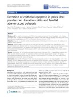
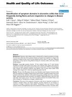
A schematic view of the experimental apparatus is
shown in Figure 1. It consisted of a rectangular plate
thermosypho n made of copper, a heating system, a con-
densing system, a data acquisition system, a power sup-
ply, a vacuum pumping unit, and a liquid filling device.
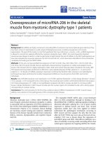
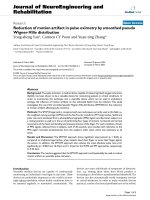
The rectangular thermosyphon shown in Figure 2 was
vertically positioned with its inner chamber size of 350
×100×8mm.ATefloncoverwasfixedtogetherwith
the copper chamber and rubber O-ring for vacuum seal-
ing. The lengths of the evaporator, the adiabatic section,
and the condenser of the thermosyphon were 100, 100,
and 150 mm, respectively. The hydraulic equivalent dia-
meter of the channel was equal to the channel thickne ss
(8 mm). The evaporator section was heated by a film
heater connected to a power supply. The condenser sec-
tion was cooled by cooling water circulating in a cooling
jacket. Thirteen thermocouples were used to measure
the system t emperature including five of them for the
temperatures of the evaporator wall, five for those of the
condenser wall, two for those of the cooling water at
the inlet and outlet, and one for that of the vapor in the
thermosyphon. A pressure transducer measuring the
system operating pressure was installed near the ther-
mocouple measuring the vapor temperature.
The experiment was carried out at three steady oper-
ating pressures of 7.38, 15.75, and 31.18 kPa, which cor-
respond to the operat ing temperatures (the va por
saturated temperatures) of 40°C, 55°C, and 70°C, re spec-
tively. The measured vapor temperature in the vapor
line was taken as the operating temper ature. Tempera-
ture and velocity of the cooling water were carefully
controlled to keep the operating pressure at a constant
value for varying heat fluxes. A data acquisition system
was used to collect the digital signals of the thermocou-
ples and the pressure transducer.
Before each test, the vacuum pumping process and
liquid preheating process were performed to remove the
gases dissolved in the thermosyphon. The vacuum pres-
sure was pumped to be less than 8 × 10
-3
Pa to el imi-
nate the influence of incondensable gases. Rationed
nanofluid was filled into the thermosy phon through
vacuum valves. The filling volume was kept at 25% of
that of the thermosypho n, 87.5% of that of the
V A
5
1
2
3
4
6
7
8
9
9
10
1
1
12
13
14
15
P
Figure 1 Schematic of experimental apparatus.
thermocouple locatio
n
P
Figure 2 Schematic of the thermosyphon (unit, millimeter).
Yang and Liu Nanoscale Research Letters 2011, 6:494
/>Page 3 of 12
evaporator. In the run, the heating power was gradually
increased by an increment of 5%. When the measured
wall temperature increased abruptly and could not hold
a steady state, which indicated that a dry-out phenom-
enon occurred on the wall, the heating power supply
was instantly switched off. Then, the run was restarted
from the former steady heating power, and the power
was then increased in an increment of 1% of the former
power. When the measure d wall temperatures once
again increased abruptly and could not hold a steady
state, the electric power supply was instantly switched
off, and the test was stopped. The MHF value was deter-
mined from the heating power of the former time.
To investigate the surface morphology of the heated
surface during the evaporating process, a polished cop-
per sheet with an area of 10 × 10 mm was soldered to
the inner surface of the evaporator and the condenser
using soldering tin. The copper sheet was taken off after
the experiment by melting the soldering tin. The scan-
ning electron microscope (SEM) pictures and the con-
tact angles of working fluids were all taken and
compared using the copper sheet.
Heat flux, q, is calculated by:
q =
(
VI − Q
hl
)
/
A
(1)
The heat transfer coefficient (HTC), h,iscalculated
by:
h =
q
T
(2)
The uncertainties of q and h are calculated by:
U
q
q
=
(
U
V
V
max
)
2
+(
U
I
I
max
)
2
+(
U
A
A
max
)
2
+(
U
Q
hl
Q
hl
)
2
(3a)
U
h
h
=
(
U
q
q
)
2
+(
U
T
T
)
2
(3b)
The maximum temperature uncertainty of the ther-
mocouple was 0.2 K. The maximum uncertainties of the
power meter and the pressure transducer were 0.5% and
0.2%, respectively. The uncertainty caused by the heat-
ing area should be less than 0.5%. The uncertainty of
the MHF should be 6.0%, and the maximum uncertainty
of the HTC was estimated to be 7.4%.
Working fluids
Surface-functionalized silica nanoparticles were used to
make a kind of stable nanofluid. The functionalization
was achieved by grafting silanes to the surface of silica
nanoparticles as was introduced by Yang and Liu [26].
Silica nanoparticle powders with an average diameter of
about 30 nm and a silane of (3-glycidoxylproyl)
trimethyoxysilane (CAS number 2530-83-8) were used
for the functionalizing process. The mass ratio of the
reacting silane and silica n anoparticles was 0.115. Dis-
perse functionalized nanoparticle s into water and then
keep the solution at the environmental temperature of
50°C for 12 h. The obtained solution was called functio-
nalized nanofluid.
Functionalized nanoparticles can still keep dispersing
well after the nanofluid has been standing for 12 months
even at the mass concentration of 10%, and no sedimen-
tation was observed. However, obvious sedimentation of
traditional nanofluid (nanofluid consisting of nanoparti-
cles without functionalization) was observed after several
days. Traditional nanofluid was also prepare d in this
study by dispersing and oscillating nanoparticles in
water. Silica nanoparticle powders were firstly dispersed
into deionized water, and the suspe nsion was then oscil-
lated in an ultrasonic bath for 12 h. The maximum
mass concentrations of functionalized nanofluid and tra-
ditional nanofluid were both 2.5 wt.% in the present
study.
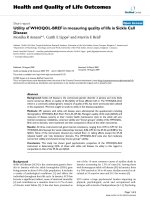
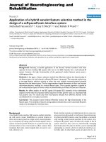
Figure 3 shows the transmission electron microscope
(TEM) pictures of functionalized nanofluid and tradi-
tional nanofluid. As is shown, functionalized nan opa rti-
cles have no aggregation and can disperse well. The
steric stabilization effect an d the solubility rule of simi-
larity help nanoparticles disperse uniformly in the base
fluid. However, nanoparticles in traditional nanofluid
aggregate each othe r and do not uniformly disperse in
the base fluid.
The steric stabilization effect arises from the fact that
polymers gathering on the surface of nanoparticles
occupy a certain amount of space. If nanoparticles are
brought too close together, the space is compressed. An
associated repulsive force helps separate nanoparticles
from each other and restrains the aggregation of nano-
particles. The grafted silanes mentioned abov e form the
steric stabilization effect and help the nanoparticles dis-
perse uniform in the base fluid.
Besides, to achieve a better and larger solubility of
nanoparticles in water, silanes containing polar struc-
tures are chosen. Due to the solubility rule of similar-
ity, polar substances are soluble with each other. The
polar structure grafted on the surface of the silica
nanoparticles increases the solubility of functionalized
nanoparticles in water (which is also a polar
substance).
Thermophysical properties including the thermal
conductivity, the viscosity, and the surface t ension of
functionalized nanofluid and traditional nanofluid have
been introduced by Yang and Liu [26]. For the conve-
nience of readers to get a quantitative view, these
parameters are also listed in Tables 1, 2, and 3,
respectively.
Yang and Liu Nanoscale Research Letters 2011, 6:494
/>Page 4 of 12
The density of nanofluids is calculated as:
ρ
nf
=
1 − ω
ρ
w
+
ω
ρ
n
p
−
1
(4)
The specific heat of nanofluids is calculated as:
ρ
nf
c
p,nf
= ρ
np
c
p,np
ϕ + ρ
w
c
p
,w
(
1 − ϕ
)
(5)
The latent heat of nanofluids is the same as that of
water.
Experimental results and discussions
Surface characteristics of heated surfaces after the
experiment using nanofluids
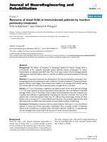
Figure 4 shows the SEM pictures of the heated sur-
faces in the evaporator (copper sheets mentioned in
“ Experimental apparatus and process” ) after the test
using water, functionalized nanofluid, and traditional
nanofluid (called the water-boiled surface, the functio-
nalized nanofluid-boiled surface, and the traditional
nanofluid-boiled surface, respectively). T he mass con-
centration of both nanofluids was 1.5 wt.%. The test
was carried out at an operating temperature of 40°C.
As shown in Figure 4, a deposition layer forms on the
traditional nanofluid-boiled surface. However, no
deposition layers exist on the functionalized nanofluid-
boiled surface. For traditional nanofluid, a part of the
reunion bodies of nanoparticles will deposit and be
attached to the heated surface. With the evaporating
process keep g oing, more nanoparticles are atta ched to
the heated surface. This results in the forming of the
deposition layer, and the layer thickens gradually with
the evaporating pro cess.
For functionalized nanofluid, however, nanoparticles
in single state cannot form a reunion body; the nanopar-
ticles settled out of the nanofluid can still resolve in the
base fluid due to the steric effect and the solubility rule
of similarity of the silane. Therefore, no deposition layer
exists for functionalized nanofluid. The main purpose of
thepresentstudyistoinvestigatethesoleeffectofthe
thermophysical properties of nanofluids on the thermal
performance of the thermosyphon under the condit ion
that no coating layer exists on the smooth heated sur-
face. This can help eliminate the effect of the surface
characteristics.
The SEM pictures of the condensing surfaces in the
condenser after the test using functionalized nanofluid
and traditional nanofluid were also taken (not plotted in
the paper). Different from the surface characteristics of
the traditional nanofluid-boiled surface, no deposition
layer forms on condensing surfaces for traditional
nanofluid.
(
a
)
(
b
)
Figure 3 TEM pictures of nanofluids. (a) Traditional nanofluid and (b) functionalized nanofluid.
Table 1 Thermal conductivity ratio of two kinds of nanofluids to the base fluid
Mass concentration
(wt.%)
Functionalized nanofluid
(20°C)
Functionalized nanofluid
(40°C)
Functionalized nanofluid
(60°C)
Traditional nanofluid
(20°C)
0.5 1.01 1.015 1.019 1.014
1 1.0142 1.022 1.027 1.018
1.5 1.0149 1.025 1.032 1.02
2 1.0163 1.028 1.037 1.021
2.5 1.0189 1.033 1.043 1.0267
Yang and Liu Nanoscale Research Letters 2011, 6:494
/>Page 5 of 12
Figure 5 shows the contact angle pictures of work-
ing fluids on heated surfaces (copper sheets men-
tioned in Sec. 2"Experimental apparatus and
process” ). Contact angles were taken using the drop
sessile method. Heated surfaces were the ones after
the tests using working fluids (with the liquid tem-
peratures of 40°C, 55°C, and 70°C and the mass con-
centration of 1.5 wt.%). The test environmental
temperature was also equivalent to 40°C, 55°C, and
70°C, respectively. As is shown, the contact angle of
water on the water-boiled surface is 83.9°, that of
functionalized nanofluid on the functionalized nano-
fluid-boiled surface is 81°, and that of traditional
nanofluid on the traditional nanofluid-boiled surface
is 21.9° at the temperature of 40°C. The contact angle
of functionalized nanofluid only decreases slightly
compared with water while that of traditional nano-
fluid decreases greatly. The deposition layer formed
by nanoparticles in traditional nanofluid improves the
wettability of nanofluids, which leads to a great
reduction of the contact angle. The contact angle
shows similar changing trend at other temperatures.
Surface roughness of the heated surface is measured
for nanofluids under different mass concentrations
giveninTable4.Asisshown,theaverageroughness
after the boiling test using the f unctionalized nano-
fluid-boiled surface is basically the same as that of
water. On the other hand, the surface roughness after
the boiling test using traditional nanofluid decreases
significantly compared w ith the water case. The reason
should be that the coating layer formed by nanopati-
cles decreases the surface roughness. The average
roughness of the traditional nanofluid-boiled surface
keeps nearly the same in the whole concentration
range tested.
Heat transfer characteristics of functionalized
nanofluid
Average wall temperatures of the evaporator using
functionalized nanofluid
Figure 6 shows the average wall temperatures of the
evaporator using functionalized nanofluid at different
heat fluxes under the fixed operating temperature of 40°
C. As is shown, the average wall temperatures using
functionalized nanofluid decreases compared with the
water case. They decrease with increasing mass concen-
trations and the trend slows down gradually. The
decrease also increases with increasing the wall heat
flux. Functionalized nanofluid enhances the evapor ati ng
heat transfer of the thermosyphon. Not plotted in this
paper, the average wall temperatures hold the sam e
trend at other operating temperatures.
The evaporating heat transfer coefficient
Figure 7 illustrates the evaporating heat transfer curves
(boiling curves) of functionalized nanofluid in thermosy-
phon at the operating temperatures of 40°C, 55°C, and
70°C. The mass concentration is 0% (water), 0.5, 1.0,
1.5, 2.0, and 2.5 wt.%, respectively. As is indicated, the
heat transfer coefficient (HTC) of functionalized nano-
fluid increases compared with that of water. Also, it
increases with the increase of the mass concentration of
nanoparticles, and the incre asing trend slows down gra-
dually. There are not much changes for the HTC
enhancement ratio when the concentration reaches and
exceeds 1.5 wt.%. The evaporating HTC of functiona-
lized nanofluid increases maximally by 17% at the oper-
ating temperature of 40°C. In addition, the MHF of
functionalized nanofluid is quite close to that of water,
which indicates that functionalized nanofluid have
nearly no effects on the MHF enhancement.
Table 2 Viscosity ratio of two kinds of nanofluids to the base fluid
Mass concentration
(wt.%)
Functionalized nanofluid
(20°C)
Functionalized nanofluid
(40°C)
Functionalized nanofluid
(60°C)
Traditional nanofluid
(20°C)
0.5 1.083 1.076 1.068 1.025
1 1.13 1.114 1.108 1.052
1.5 1.156 1.139 1.133 1.078
2 1.19 1.172 1.159 1.1
2.5 1.223 1.203 1.189 1.12
Table 3 Surface tension ratio of two kinds of nanofluids to the base fluid
Mass concentration
(wt.%)
Functionalized nanofluid
(20°C)
Functionalized nanofluid
(40°C)
Functionalized nanofluid
(60°C)
Traditional nanofluid
(20°C)
0.5 0.72278 0.71 0.697 0.7858
1 0.71875 0.704 0.686 0.779
1.5 0.71903 0.701 0.684 0.77373
2 0.70833 0.69 0.676 0.765
2.5 0.7125 0.693 0.678 0.759
Yang and Liu Nanoscale Research Letters 2011, 6:494
/>Page 6 of 12
The calculated HTC curves for water plotted also in
Figure 7. Due to the complexity of the heat transfer in
thermosyphon, it is hard to find predicting c orrelations
to exactly calculate its evaporating HTC. Therefore, a
well-known empirical correlation proposed by Kutate-
ladze, which can well predict the HTC of pool boiling
on a smooth metal surfac e [27], is used to estimate the
evaporating CHF in the boiling region.
h
λ
σ
g(ρ
l
− ρ
v
)
=7.0× 10
−4
Pr
l
0.35
× [
q
ρ
v
h
f
g
ν
l
σ
g(ρ
l
− ρ
v
)
]
0.7
[
p
σ
σ
g(ρ
l
− ρ
v
)
]
0.
7
(6)
As shown in Figure 7, the calculated and experimental
values keep good agreement at low and me dium heat
flux. Then the deviation gradually increases. This is
because the heat transfer mode in the evaporator of the
thermosyphon is similar to the pool boiling heat transfer
at low and medium heat flux, but dry-out area on the
heated surface will appear and it increases gradually
with increasi ng the heat flux, leading to the deviation of
the present study with the pool boiling heat transfer.
With the increase of the dry-out area, the HTC flattens
and finally decreases till the dry-out limit happens.
Therefore, Equation 6 fails to predict the HTC at high
heat flux.
Figure 8 indicat es the effect of the mass concentration
on the evaporating HTC enhancement ratio of functio-
nalized nanofluid (w = 1 .5 wt.%). Here, the HTC
enhancement ratio is an average of ratios in the whole
heat flux range tested. As shown in Figure 8, the eva-
porating HTC enhancem ent ratio decreases slightly with
increasing operating temperature. At t he mass co ncen-
tration of 1 .5 wt.%, the evaporating HTC enhancement
ratio ranges within 1.12 to 1.16, 1.07 to 1.12, and 1.53
to 1.08, respectively, for the operat ing temperatures of
40°C, 55°C, and 70°C. The operating temperature has no
meaningful influence on the evaporating HTC enhance-
ment ratio.
Besides, the HTC ratio increases with increasing heat
flux at all o perating temperatures. This effect can be
explained by the Brownian motion, and the thermo-
phoresis effect [28]. The thermophoresis effect holds
water traditional nanofluid
f
u
n
c
ti
o
naliz
ed
nan
o
fl
u
i
d
Figure 4 SEM pictures of heated surfaces.
Yang and Liu Nanoscale Research Letters 2011, 6:494
/>Page 7 of 12
that nanopar ticles can diffuse under the effect of a tem-
perature gradient. The diffusion increases with increas-
ing t emperature gradient. In the boiling heat transfer, a
great temperature gradient exists for the nanofluid near
the heated surface. It increases with increasing heat flux
and correspondingly increase s the diffusion of nanopar-
ticles, and hence the heat transfer is enhanced. Mean-
while, higher temperature leads to stronger Brownian
motion, which also enhances the energy transportation.
Therefore, the HTC enhancement increases with
increasing heat flux.
From Figure 8, it is found that the HTC enhancement
results mainly from the sole effect of the thermophysical
properties of the nanofluid. According to Equation 6,
the HTC and the main thermophysical properties of
working fluids hold the following relation at the same
heated surface state:
h
nf
h
w
=
λ
nf
λ
w
ν
nf
ν
w
−0.35
σ
nf
σ
w
−0.
5
(7)
The calculated and experimental values hold a devia-
tion of about 15%. This deviation is acceptable due to
the experiment error and the inaccuracy of the pre-
dictedequation.SoitshouldbeconsideredthatEqua-
tion 7 can generally predict the HTC enhancement
effect caused by the change of the thermophysical
properties.
Therefore, the HTC enhancement of the evaporating
heat transfer of functionalized nanofluid can be
explained by the change of thermophysical properties.
Functionalized nanofluid increases the thermal co nduc-
tivity, the viscosity and decreases the surface tension
compared with water. Both the changes of t he thermal
conductivity and the surface tension increase the HTC
while that of the viscosity decreases the HTC. The
incre asing effect overwhelms the decrea sing effect, lead-
ing to the HTC enhancement.
However, it should be noted that the experimental
data show also an increase trend of the HTC with the
increase of the mass concentration. This cannot be
explained by Equation 7 since the calculated values are
close with each other at different mass concentrations.
Also, the HTC enhancement decreases slightly with
increasing the operating temperature, which is contrary
to the calculated change trend. This shows that Equa-
tion 7 can quantitatively calculate the HTC enhance-
ment but is still awkward to qualitatively do that. We
will focus on these problems for next-step study.
Maximum heat flux
There are many empirical a nd semiempirical equations
used for predicting the maximum heat flux (MHF) of a
thermos yphon. Imura [29] proposed the following equa-
tion in 1983 to predict the MHF of a thermosyphon:
q
max
=0.16h
fg
4
ρ
2
v
gσ (ρ
l
− ρ
v
)
1 − exp
−(d/L
e
)(ρ
l
/ρ
v
)
0.13
(8)
Pioro [30] proposed a similar equation in 1987, which
contains the parameter of the contact angle:
q
max
=0.131h
fg
4
ρ
2
v
gσ (ρ
l
− ρ
v
)
1 − exp
−(d/L
e
)(ρ
l
/ρ
v
)
0.13
cos
1.8
(β − 55)
0
.
8
(9)
83.9°(40
o
C) 87.7°(55
o
C) 89.2°(70
o
C)
water
81°(40
o
C 84.1°(55
o
C) 86.3°(70
o
C)
functionalized nanofluid (1.5 wt%)
21.9°(40
o
C) 23.2°(55
o
C) 24.7°(70
o
C)
traditional nanofluid
(
1.5 wt%
)
Figure 5 Contact angle pictures of working fluids.
Table 4 Average roughness of the nanofluid-boiled surfaces
Mass concentration R (nm) of functionalized nanofluid-boiled surface R (nm) of traditional nanofluid-boiled surface
0 35.1 35.1
0.5 wt.% 37.2 21.4
1.0 wt.% 34.5 23.9
1.5 wt.% 39.3 20.5
2.0 wt.% 40.8 21.1
2.5 wt.% 36.5 19.8
Yang and Liu Nanoscale Research Letters 2011, 6:494
/>Page 8 of 12
The experimental MHF of functio nalized nanofluid
and those predicted by Equations 8 and 9 are shown in
Table 5. The deviation in Table 5 is defined as
Dev = (q
max,
p
r
− q
max
)/q
ma
x
(10)
As shown in Table 5, the maximum deviation of the
experimental values and the predicted ones by Equa-
tions 8 and 9 for water is smaller than 13.0%. The maxi-
mum deviation for functionalized nanofluid is 6.8%. The
experimental results indicate that Equations 8 and 9 can
also be used to predict the MHF of functionalized nano-
fluid in a thermosyphon. Since the experimental data
keep well with traditional theory, no meaningful nano-
fluid effect is found for the MHF of functionalized
nanofluid.
Condensing heat transfer characteristics
In general, for Newton fluids, the condensing heat trans-
fer of the falling film along the vertical wall can be esti-
mated by the well-known Nusselt correlation.
h
c
= 0.943
ρ
l
gλ
3
l
(ρ
l
− ρ
v
)
h
fg
+0.68C
l
T
c
μ
l
L
c
T
c
1
4
(11)
Figure 9 shows the experimental data of the conden-
sing HTC for both water and functionalized nanofluid
in a thermosyphon at different operating temperatures.
The predicted curves of Equation 11 for water and func-
tionalized nanofluid (w = 1 .5 wt.%) are also shown for
comparison. It is found that all experimental data are
about 15% less than the calculated values. This is
because the flow of the falling film and vapor is coun-
tercurrent in the present thermosyphon, and it is rea-
sonable that the experimental data are somewhat less
than the calculated values. On the other hand, the con-
densing heat transfer characteristics of functionalized
nanofluid are almost the same a s that of water. Adding
functionalized nanopa rticles into water does not change
the conde nsing heat transfer of the thermosyphon. This
experimental result may be well explained by the tradi-
tional theory using Equation 11. According to the calcu-
lated curves of the condensing HTC of functionalized
nanofluid by Equation 11, there exist no meaningful
changes between the calculated condensing HTC of
0 10203040506070809010011
0
40
42
44
46
48
50
52
54
56
58
60
62
64
66
68
70
72
74
76
78
80
T
e
(
o
C)
functionalized nanofluid
T
S
=40
o
C
water
ω
=0.5%
ω
=1.0%
ω
=1.5%
ω
=2.0%
ω
=2.5%
q
e
(kW/m
2
)
Figure 6 Average wall temperature of the evaporator using
functionalized nanofluid.
0 20 40 60 80 100 120 140 160
1000
1500
2000
2500
3000
3
5
00
h
e
(kW/m
2
K)
Functionalized nanofluid
T
s
=40
o
C
water
w=0.5%
w=1.0%
w=1.5%
w=2.0%
w=2.5%
q
e
(kW/m
2
)
Eq. (6)
(a)
0 20 40 60 80 100 120 140 160
1000
1500
2000
2500
3000
3500
4000
h
e
(kW/m
2
K)
Functionalized nanofluid
T
s
=55
o
C
water
w=0.5%
w=1.0%
w=1.5%
w=2.0%
w=2.5%
q
e
(kW/m
2
)
Eq. (6)
(b
)
0 20 40 60 80 100 120 140 160 180
1000
1500
2000
2500
3000
3500
4000
4500
Functionalized nanofluid
T
S
=70
o
C
water
w=0.5%
w=1.0%
w=1.5%
w=2.0%
w=2.5%
q
e
(kW /m
2
)
h
e
(W/m
2
/K)
Eq. (6)
(
C
)
Figure 7 Ef fect of mass concentration on the evaporating HTC
of functionalized nanofluid. (a) p = 7.4 kPa, (b) p = 15.75 kPa, (c)
p = 31.38 kPa.
Yang and Liu Nanoscale Research Letters 2011, 6:494
/>Page 9 of 12
functionalized nanofluid and water. The changes of the
thermophysical properties have no meaningful effec t on
the condensing HTC of functionalized nanofluid.
According to the above discussion, functionalized
nanofluid can enhance the evaporating HTC of the ther-
mosyphon but has no effe ct on the MHF and the con-
densing HTC. T he heat transfer characteristics of
functionaliz ed nanofluid result mainly from the changes
of the thermophysical properties of nanofluids. There-
fore, functionalized nanofluid can be considered as an
ordinary working fluid and no meaningful nanofluid
effect exists for functionalized nanofluid in the
thermosyphon.
Heat transfer characteristics of traditional
nanofluid
Figure 10 indicates the evaporating HTC curves of tradi-
tional nanofluid under the three operating temperatures.
The mass concentration of traditional nanofluid is fixe d
at 1.5 wt.%. The HTC curves of water and functiona-
lized nanofluid are plotted also in Figure 10 for compar-
ison. As shown in Figure 10, the evaporating HTC of
traditional nanofluid decreases meanly by 7%, 9%, and
11% for the operating temperature of 40°C, 55°C, and
70°C, respectively. The de terioration increases with
decreasing operating temperature. On the other hand,
the MHF of traditional nanofluid increases obviously
with the enhancement ranging within 48% to 63%.
As discussed in the above section, the thermophysical
properties of functionalized nanofluid result in HTC
enhancement (the data of functionalized nanofluid are
also plotted in Figure 10). Traditional nanofluid and
functionalized nanofluid have similar trends on the ther-
mophysical properties. Therefore, the thermophysical
properties of traditional nanofluid cannot result in the
HTC deterioration, and the change of the surface char-
acteristics should mainly attribute to the HTC
deterioration.
The deposition layer formed on the heated surface by
nanoparticles changes the wettability or the solid-liquid
contact angle, the active nucleation site density of the
heated surface, and the surface roughness. It also
increases the heat resistance of the heated surface. The
reduction of the contact angle (the increase in the wett-
ability) and the surface roughness, the increase of the
heat resistance all results in the HTC deteriora tion
according to traditional boiling theory, but the deposi-
tion layer can also increase the active nucleation site
density that can enhance the HTC. The effect of tradi-
tional nanofluid on the HTC results from the aggrega-
tion of all above factors.
It is hard to estimat e quantitatively the number
changes of the active nucleation site density, but it
should be concluded that the influencing factors leading
to the HTC deterioration overwhelm those leading to
the HTC enhancement, resulting in the HTC
deterioration.
The effect of traditional nanofluid on the condensing
heat transfer is the same with that of functionalized
nanofluid. Adding nanoparticles does not change the
condensing heat transfer. The reason can follow the
same explanation for functionalized nanofluid.
For traditional nanofluid, the experimental MHF can-
not be predicted by Equations 8 and 9 because the con-
tact angle of traditional nanof luid on the heated surface
is over the applicable range of Equations 8 and 9. As is
shown in Figure 5, the contact angle of traditional nano-
fluid in the present study is about 20°; however, Equa-
tion 9 can only be used when the contact angle is larger
than 55°.
BasedonEquation9,anewequationisarranged
which expands the applicable arrangement o f the
0.0 0.5 1.0 1.5 2.0 2.5 3.0
1.00
1.05
1.10
1.15
1.20
1.25
1
.
30
Eq. (7) for T
S
=40
o
C
Eq. (7) for T
S
=55
o
C
w
(
%
)
Operating temperature
T
S
=40
o
C T
S
=55
o
C T
S
=70
o
C
h
e,n
/ h
e,0
Eq. (7) for T
S
=70
o
C
Figure 8 Effect of mass concentration of functionalized
nanofluid on the HTC enhancement ratio.
Table 5 MHF of water and functionalized nanofluid
Water Functionalized nanofluid (1.5 wt.%)
Operating temperature (°C) MHF (W/m
2
/k) Deviation of equation 8 Deviation of equation 9 MHF (W/m
2
/k) Deviation of equation 9
70 160,863 12.7% -9.3% 154,602 6.5%
55 128,738 13.0% -7.7% 124,168 6.8%
40 108,582 2.6% -12.6% 104,576 -2.6%
Yang and Liu Nanoscale Research Letters 2011, 6:494
/>Page 10 of 12
contact angle to 20° to 80°. The new correlation holds a
good one to one correspondence for the present MHF
data.
q
max
= 0.1424h
fg
4
ρ
2
v
gσ (ρ
l
− ρ
v
)
1 − exp
−(d/l
e
)(ρ
l
/ρ
v
)
0.13
(1+cosβ)
0.
8
(12)
The comparison o f the experimental data with Equa-
tion 12 is shown in Figure 11. The deviation of Equation
12 lies within 5% for all working fluids, including water,
functionalized nanofluid, and traditional nanofluid.
Equation 12 confirms that the MHF enhancement of
traditional nanofluid results from the decrease of the
contact angle. The deposition layer improves its wett-
ability and decrease the contact angle. For functionalized
nanofluid, the contact angle only changes very slightly.
Therefore, no meaningful enhancement of MHF exists
for functionalized nanofluid.
Conclusions
Surface-functionalized silica nanoparticles were used to
prepare a kind of stable nanofluid (called functiona-
lized nanofluid). An experiment was carried out to
study the thermal performance of a thermosyphon
using water, functionalized nanofluid, and traditional
nanofluid (the nanofluid consisting of unfunctionalized
nanoparticles) under steady operating pressures.
Results a re given as:
1. The covalent bonding “ Si-O- Si” helps to maintain
the steric stabilization effect formed by the grafting
silanes which contributes to the long-term stability of
nanofluids. Functionalized nanoparticles can still keep
dispersing well after the nanofluid has been standing for
a long time, and no sedimentation was observed.
2. A deposition layer exists o n the heated surface dur-
ing the experiment using traditional nanofluid; however,
no layer exists for functionalized nanofluid. There exist
great differences for heat transfer characteristics of func-
tionalized nanofluid and traditional nanofluid. The dif-
ferences mainly result from the changes of surface
characteristics of the heated surfaces but not from the
nanofluids themselves.
3. Functionalized nanofluid can enhance the evaporat-
ing HTC, while it has generally no effect on the MHF.
The HTC enhancement of functionalized nanofluid
results mainly from the changes of the thermophysical
properties of functionalized nanofluid.
4. Traditional nanofluid de teriorates the evaporating
HTC but enhances the MHF. The deposition layer
mainly results in the HTC deterioration. The great
decrease of the contact angle on the deposition layer
corresponds to the MHF enhanc ement for traditional
nanofluid.
0 20406080100120
0
5000
10000
15000
20000
25000
30000
35000
h
c
(kW/m
2
/K )
Eq. (11) for water
Eq. (11) for nanofluid (w=1.5 wt%, T
S
=70
o
C)
Water
T
S
=40
o
C
T
S
=55
o
C
T
S
=70
o
C
Functionalized nanofluid (1.5 wt%)
T
S
=40
o
C
T
S
=55
o
C
T
S
=70
o
C
q
c
(kW/m
2
)
Figure 9 Condensing HTC curves of functionalized nanofluid.
0 50 100 150 200 250 30
0
0
500
1000
1500
2000
2500
3000
3500
4000
q
e
(kW/m
2
)
h
e
(W/m
2
/K)
q
e
(kW/m
2
)
Water
T
s
=40
o
C
T
s
=55
o
C
T
s
=70
o
C
Traditional nanofluid(1.5 wt%)
T
s
=40
o
C
T
s
=55
o
C
T
s
=70
o
C
Functionalized nanofluid (1.5 wt% )
T
s
=40
o
C
Figure 10 Evaporating HTC curves of traditional nanofluid.
15 20 25 30 35 40 45 50 55 60 65 70 75 80 85 9
0
60
80
100
120
140
160
180
200
220
240
260
280
300
q
max
(kW/m
2
)
Eq. (12) for
functionalized
nanofluid
Eq. (12) for
traditional
nanofluid
traiditional nanofluid (1.5 wt%)
water
functionalized nanofuid (1.5 wt%)
T
S
(
o
C)
Eq. (12)
for water
Figure 11 Comparison of experimental and predicted MHF of
working fluids.
Yang and Liu Nanoscale Research Letters 2011, 6:494
/>Page 11 of 12
5. Functionalized nanofluid and trad itional nanofluid
both have no effects on the condensing heat transfer of
the thermosyphon.
6. In the present study, no meaningful nanofluid effect
isfoundfortheheattransferofnanofluidsinthe
thermosyphon.
Subscripts
C: Condenser; e: Evaporator; hl: Heat loss; l: Liquid; nf:
Nanofluid; np: Nanoparticles; max: Maximum; pr: Pre-
dicted value; v: Vapor; w: Water.
Abbreviations
Nomenclature
A: Heating area (square meters); c: Specific heat (joules per kilogram per
Kelvin); d: Thickness of the inner chamber of thermosyphon (meter); Dev:
Deviation; g: Gravity acceleration (meter per square second); h: Heat transfer
coefficient (watts per Kelvin per square meter); h
fg:
: Latent heat of
evaporation (joules per kilogram); I: Current (A); L: Length (meter); p: Pressure
(kilopascal); Pr: Prandtl number (-); Q: Heat power (watts); q: Heat flux (watts
per square meter); T: Temperature (Kelvin); ΔT: Wall superheat (Kelvin); U:
Uncertainty; V: Voltage (Volts); λ: Thermal conductivity (watts per meter per
Kelvin); β: Contact angle (degrees); w: Mass concentration; σ: Surface tension
(Newton per meter); μ: Dynamic viscosity (kilograms per meter per second);
ρ: Density (kilograms per cubic meter)
Authors’ contributions
XFY carried out the experiment, participated in the theoretical calculation
and drafted the manuscript. ZHL carried out the design of the study plan
and performed the design of the theoretical model. All authors read and
approved the final manuscript.
Competing interests
The authors declare that they have no competing interests.
Received: 30 October 2010 Accepted: 16 August 2011
Published: 16 August 2011
References
1. Choi SUS: Enhancing thermal conductivity of fluids with nanoparticles. J
ASME FED 1995, 231:99.
2. Eastman JA, Choi SUS, Li S, Yu W, Thompson LJ: Anomalously increased
effective thermal conductivities of ethylene glycol-based nanofluids
containing copper nanoparticles. Appl Phys Lett 2001, 78:718-720.
3. Das SK, Putra N, Thiesen P, Roetzel W: Temperature dependence of
thermal conductivity enhancement for nanofluids. J Heat Trans 2003,
125:567.
4. Xuan Y, Li Q: Heat transfer enhancement of nanofluids. J Heat Trans 2003,
125:151.
5. Putra N, Roetzel W, Das SK: Pool boiling characteristics of nanofluids. Heat
and Mass Transfer 2003, 39:775.
6. Wen D, Ding Y: Experimental investigation into convective heat transfer
of nanofluids at the entrance region under laminar flow conditions. Int J
Heat Mass Tran 2004, 47:5181.
7. Heris SZ, Etemad SG, Esfahany MN: Heat transfer enhancement using
Al2O3/water nanofluid in a two-phase closed thermosyphon. Int
Commun Heat Mass 2006, 33:529.
8. Kang SW, Wei WC, Tsai SH, Yang SY: Experiment investigation of silver
nanofluid on heat pipe thermal performance. Appl Therm Eng 2006,
26:2377.
9. Shafahi M, Bianco V, Vafai K, Manca O: Thermal performance of flat-
shaped heat pipes using nanofluids. Int J Heat Mass Tran 2010, 53:1438.
10. Tsai CY, Chien HT, Ding PP, Chan B, Luh TY, Chen PH: Effect of structural
character of gold nanoparticles in nanofluid on heat pipe thermal
performance. Mater Lett 2004, 58:1461.
11. Chen YT, Wei WC, Kang SW, Yu CS: Effect of nanofluids on flat heat pipe
thermal performance. The 24th IEEE Semiconductor Thermal Measurement
and Management Symposium, IEEE: March 16-20 2008; San Jose 2008, 16-19.
12. Kang SW, Wei WC, Tsai SH, Huang CC: Experimental investigation of
nanofluids on sintered heat pipe thermal performance. Appl Therm Eng
2009, 29:973.
13. Riehl RR: Analysis of loop heat pipe behaviour using nanofluid, in:
Proceedings of heat powered cycles international conference (HPC).
Heat Powered Cycles International Conference (HPC), September 11-14, 2006,
New Castle, UK paper No. 06102 .
14. Ma HB, Wilson C, Borgmeyer B, Park K, Yu Q, Choi SUS, Tirumala M: Effect
of nanofluid on the heat transport capability in an oscillating heat pipe.
Appl Phys Lett 2006, 88:143116.
15. Lin YH, Kang SW, Chen HL: Effect of silver nano-fluid on pulsating heat
pipe thermal performance. Appl Therm Eng 2008,
28:1312.
16. Xue H, Fan J, Hu Y, Hong R, Cen K: The interface effect of carbon
nanotube suspension on the thermal performance of a two-phase
closed thermosyphon. J Appl Phys 2006, 100:104909.
17. Khandekar S, Joshi YM, Mehta B: Thermal performance of closed two-
phase thermosyphon using nanofluids. Int J Therm Sci 2008, 47:659.
18. Mehta B, Khandekar S: Embedded pulsating heat pipe radiators. 14th
International Heat Pipe Conference (14th IHPC): April 22-27 2007; Florianopolis
2007.
19. Naphon P, Assadamongkol P, Borirak T: Experimental investigation of
titanium nanofluids on the heat pipe thermal efficiency. Int Commun
Heat Mass 2008, 35:1316.
20. Naphon P, Thongkum D, Assadamongkol P: Heat pipe efficiency
enhancement with refrigerant-nanoparticles mixtures. Energy Conversion
and Management 2009, 50:772.
21. Liu ZH, Yang XF, Guo GL: Effect of nanoparticles in nanofluid on thermal
performance in a miniature thermosyphon. J Appl Phys 2007, 102:013526.
22. Liu ZH, Yang XF, Wang GS, Guo GL: Influence of carbon nanotube
suspension on the thermal performance of a miniature thermosyphon.
Int J Heat Mass Tran 2010, 53:1914.
23. Noie SH, Heris SZ, Kahani M, Nowee SM: Heat transfer enhancement using
Al2O3/water nanofluid in a two-phase closed thermosyphon. Int J Heat
Fluid Fl 2009, 30:700.
24. Paramatthanuwat T, Boothaisong S, Rittidech S, Booddachan K: Heat
transfer characteristics of a two-phase closed thermosyphon using de
ionized water mixed with silver nano. Heat Mass Transfer 2010, 46:281.
25. Teng TP, Hsu HG, Mo HE, Chen CC: Thermal efficiency of heat pipe with
alumina nanofluid. Journal of Alloys and Compounds 2010, 504S:380.
26. Yang XF, Liu ZH: A Kind of Nanofluid Consisting of Surface
Functionalized Nanoparticles. Nanoscale Res Lett 2010, 5:1324.
27. Kutateladze SS: A hydrodynamic theory of changes in the boiling process
under free convection conditions. Isv Akad Nauk 1951, 4:529.
28. Buongiorno J: Heat transfer problems with nucleate boiling of liquids. J
Heat Trans 2006, 128:240.
29. Imura H, Sasaguchi K, Kozai H: Critical heat flux in a closed two-phase
thermosyphon. Int J Heat Mass Tran 1983, 26:1181.
30. Pioro IL, Voroncova MV:
Rascetnoe opredelenie predelnogo teplovogo
potoka pri kipenii zidkostej v dvuhfaznih termosifonah. Inz Fiz Zurnal
1987, 53:376.
doi:10.1186/1556-276X-6-494
Cite this article as: Yang and Liu: Application of functionalized
nanofluid in thermosyphon. Nanoscale Research Letters 2011 6:494.
Yang and Liu Nanoscale Research Letters 2011, 6:494
/>Page 12 of 12