Báo cáo hóa học: " In-body path loss models for implants in heterogeneous human tissues using implantable slot dipole conformal flexible antennas" potx
Bạn đang xem bản rút gọn của tài liệu. Xem và tải ngay bản đầy đủ của tài liệu tại đây (500.15 KB, 9 trang )
RESEARCH Open Access
In-body path loss models for implants in
heterogeneous human tissues using implantable
slot dipole conformal flexible antennas
Divya Kurup
1*
, Maria Scarpello
2
, Günter Vermeeren
1
, Wout Joseph
1
, Kristof Dhaenens
3
, Fabrice Axisa
3
,
Luc Martens
1
, Dries Vande Ginste
2
, Hendrik Rogier
2
and Jan Vanfleteren
3
Abstract
A wireless body area network (WBAN) consists of a wireless network with devices placed close to, attached on, or
implanted into the human body. Wireless communication within a human body experiences loss in the form of
attenuation and absorption. A path loss model is necessary to account for these losses. In this article, path loss is
studied in the heterogeneous anatomical model of a 6-year male child from the Virtual Family using an
implantable slot dipole conformal flexible antenna and an in-body path loss model is proposed at 2.45 GHz with
application to implants in a human body. The model is based on 3D electromagnetic simulations and is compared
to models in a homogeneous muscle tissue medium.
Introduction
A wireless body area network (WBAN) is a network,
consisting of nodes that communicate wirelessly and are
located on or in the body of a person. These nodes
form a network that exte nds over the body of the per-
son. Depending on the implementat ion, the nod es con-
sist of sensors and actuators, placed in a star or
multihop topology [1].
Applications of WBANs include medicine, s ports,
military, and multimedia, which m ake use of the free-
domofmovementprovidedbytheWBAN.AsWBAN
facilitates unconstrained movement amongst users, it
has brought a revolutionary change in patient monitor-
ing and health care facilities. Active implants placed
within the human body lead to better and faster diagno-
sis, thus improving the patient’s quality of life. Implanta-
ble devices are increasingly proving their impo rtance for
biomedical applications. The use of active implants
allows vital medical data to be collected over a longer
period in the natural environment of the patient, allow-
ing for a more accurate and sometimes even faster diag-
nosis. Active implants such as pacemakers and
implantable cardioverter defibrillators (ICDs) need to
relay information to other devices for control or moni-
toring [2]. Thus a proper and efficient modeling of the
channel is required to transfer data between implants
and other devices. Moreover, the human body is a lossy
medium which a ttenuates the waves propagating from
the transmitter (Tx) considerably before they reach the
receiver (Rx). Thus, to design an optimal communica-
tion link between nodes placed within or on the human
body a proper and e fficient path loss (PL) model is
required.
To our knowledge very limited literature exists on
propagation loss within the human body [2-6]. In [3]
initial results of an in-body propagation model in saline
water is presented. Inaccuracies lead to maximum devia-
tions of 9 dB between the measurements and simula-
tions. Also only a homogeneous medium is studied and
there are no models available for heterogeneous med-
ium. [3] considers a non-insulat ed hertzi an dipole,
hence the PL model can only be ap plied to very small
dipole antennas. [4] provides various scenarios for chan-
nel modeling but does not provide a model for path
loss. [5] discusses a link budget for an implanted cavity
slot antenna at 2.45 GHz. However, no model for a het-
erogeneous medium is suggested that can be used for
path loss simulation. [2] suggests a PL model for in-
* Correspondence:
1
Department of Information Technology, WiCa, Ghent University/IBBT,
Gaston Crommenlaan 8 Box 201, 9050 Ghent, Belgium
Full list of author information is available at the end of the article
Kurup et al . EURASIP Journal on Wireless Communications and Networking 2011, 2011:51
/>© 2011 Kurup et al; licensee Springer. This is an Open Access article distributed under t he terms of the Crea tive Commons Attribution
License (http://creativecommons .org/license s/by/2.0), which permits unrestricted use, distribution, and reproduction in any medium,
provided the original work is properly cited.
body wireless implants. However, it does not make use
of biocompatible implantable antennas. [6] suggests a
PL model for in-body wireless implants by making use
of insulated dipole antennas in a homogeneous medium.
The goal of this article is to develop an empi rical PL
model for a heterogeneous medium, using implantable
antennas, that describes the relationships between the
PL, the distance between the antennas, and the power
attenuation. Since it is difficult to carry out measure-
ments in the human body, implantable antennas are
designed by taking the dielectric properties of human
muscle tissue into consideration.
Simulations are performed at 2.45 GHz in the license
free industrial, scientific, and medical (ISM) band. This
frequency band is chosen since there are no licensing
issues in this band and the higher frequency allows the
use of a smaller antenna. Moreover, 2.45 GHz allows
higher bitrates due to the larger ba ndwidth [7]. After
carrying out the simulations in human muscle tissue,
simulations are carried out in a heterogeneous medium
for various scenarios using an enhanced anatomical
model of a 6-year-old male child from the Virtual
Family (Christ, in preparation). We use a child model
becauseinchildrenwithevidenceofinternalbleeding
and abdominal pain, correct diagnosis is a challenge and
capsule endoscopy can be used for the diagnosis of such
ailments. Capsule endoscopy has been accepted in adults
by many gastroenterologists, however its usage in chil-
dren has lagged due to the belief by pediatricians that
the pills are too large to be swallowed by children [8,9].
However, reports do suggest that children as young as
two and a half years old are successfully undergoing
capsule endoscopy, and most of the studies suggest that
majority of pediatric patients can swallow the pill
[10,11].
The PL model developed in this article focuses on
deep tissue implants, such as endoscopy capsules. In
such applications the implants are placed deep inside
the body, which we have selected up to a distance of 8
cm. A PL model will help in understanding the influ-
ence of the dielectric properties of the surrounding tis-
sues and the power attenuation of such implants. As it
is diffic ult for the manufacturers to test their system on
actual humans, the proposed model can be used by
them to evaluate the performance of in-body WBAN
system s using well specified setups and to carry out link
budget calculations.
The outline of this article is as follows. The setup and
configuration of the simulations in the homogeneous
muscle tissue medium and the heterogeneous human
model are discussed in Sects. II and III, respectively.
Section IV discusses t he results including the reflection
coefficient and the path loss of the implanted antenna s
in human muscle tissue medium and the heterogeneous
model. Section V presents the conclusions.
Homogeneous Tissue: Human Muscle Tissue
A. Setup and configuration
We first investigate wave propagation at 2.45 GHz in
human muscle tissue (relative permittivity ε
r
=50.8and
conductivity s = 2.01 S/m [12]), using s imulations for
implantable antennas. These implantable antennas oper-
ating in the 2.45 GHz ISM band are designed b ased on
recommendations set by the European Radiocommuni-
cations Committee (ERC) for ultra-low-power active
medical implants [13]. We consider the implantable
antenna as a short range device (SRD) working in the
ISM band because SRD i s intended to cover the radio
transmitters which provide either unidirectional or bi-
directional communication and have low c apability of
causing interference to other radio equipment. SRDs use
either integral, dedicated or external antennas and all
modes of modulation can be permitted subject to rele-
vant standards. The antenna s are flexible folded slot
dipole antennas embedded in biocompatible polydi-
methylsiloxane (PDMS) to make it suitable for implanta-
tion [7]. The flexible property of the antenna makes it
more convenient to be placed in different parts of the
body instead of placing a rigid structure. The antenna is
manufactured using flexible electronic technology: the
metallization resides on a flexible polyimide substrate
with a thickness of 25 μm, a relative permittivity of ε
r
=
3.5, and a loss tangent of tan δ = 0.003. Two PDMS
layers are u sed as substra te and superstrate , each with a
thickness of 2.5 mm. The dielectric properties of the
PDMS were characterized at 2.45 GHz, to be ε
r
=2.2
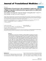
and tan δ = 0.013. The top view of the coplanar wave-
guide(CPW)fedantennaisshowninFigure1andits
dimensions are presented in Table 1. The antenna
length (L = 25.9 m m) may seem to be slightly large for
an immediate in human body, however, this is the start-
ing point to proceed with further development. It is also
feasible to shorten the CPW, matched at 50 Ohm,
whose length is now 18 mm and the saved space can
then be used for the insertion of an IC package.
1) Simulation
Simulations are performed using a 3D electromagnetic
solver SEMCAD-X (SPEAG, Switzerland), a finite-differ-
ence time-domain (FDTD) program. SEMCAD-X
enables non-uniform gridding. T he maximum grid step
in the muscle tissue medium is 1 mm at 2.45 GHz. The
simulations are carried out using the implantab le anten-
nas up to a distance of 8 cm. The muscle tissue is mod-
eled by using a cube (dimensions 150 × 150 × 280
mm
3
) with the dielectric properties of human muscle
tissue. The implantable antennas are aligned for
Kurup et al . EURASIP Journal on Wireless Communications and Networking 2011, 2011:51
/>Page 2 of 9
maximum power tran sfer and the source used is a vol-
tage source.
Heterogeneous Medium
A. Setup and configuration
We also simulate to investigate wave propagation at 2.45
GHz in a heterogeneous medium using the real implan-
table antenna proposed in Figure 1. The heterogeneous
medium is an enhanced anatomical model of a 6-year-
old male child from Virtual Family (Figure 2) (Christ, in
preparation). The model is based on magnetic resonance
images (MRI) of healthy volunteers. The male child
model (virtual family boy, VFB) has a height of 1.17 m
and a weight of 19.5 kg. The model consists of 81 differ-
ent tissues. The dielectric properties of the body tissues
have been taken from the Gabriel database [14]. Simula-
tions to determine PL are carried out using the FDTD
solver in SEMCAD-X (SPEAG, Switzerland). The
implantable antennas are placed in the trunk of the
male child model to determine PL from a distance o f 1
cm up to 8 cm for applications such as an endoscopy
capsule. The maximum step in grid setting is 1 mm.
The padding, which is the spacing added to the grid
from the bounding box of the model to the grid bound-
ary, is negative so that the grid c overs the part of the
human body entirely. The absorbing boundary condition
used is very high mode with a very high strength thick-
ness, w here a minimum level of absorption at the outer
boundary is 99.99% [15]. A transient excitation of 30
periods is set to ensure that a steady state is reached.
Since the simulation using the whole body of the male
child model consumes a lot of time, the simulation
domain is reduced to just cover the trunk o f the male
child model, however, validation for some cases has
been done with the full body of the VFB. Simulations
are carried out for various scenarios taking the path of
an endoscopy capsule into consideration:
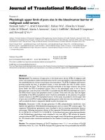
• Scenario I– Esophagus: For each scenario, the Tx
and the Rx are placed at three different positions.
The first position is at location 1 as shown in the
Figure 1 Top view of the coplanar waveguide-fed antenna.
Table 1 Size of the folded slot dipole antenna
Unit H L hIWg’ Wg’’ Wg’’’ Ws G S Gap G-S
(mm) 8.5 25.9 3.2 8.3 1.2 1.5 1.0 0.3 1.8 1.7 0.1
Kurup et al . EURASIP Journal on Wireless Communications and Networking 2011, 2011:51
/>Page 3 of 9
Figure 2. He re the Tx antenna is placed in the eso-
phagus (ε
r
=62.15ands = 2.2 S/m) of the VFB
and the receiving antenna is placed at a separation
of1cmfromtheTxupto5cminstepsof5mm
as shown in the Figure 2. The Rx antenna traverses
through the lungs (ε
r
= 34.42 and s =1.24S/m)in
this position. Position 2 in this scenario is such
that the Tx and Rx antennas are placed 1 cm
below location 1 and this is indicated as location 2
in the Figure 2. In position 3 the Tx and Rx anten-
nas are placed 2 cm below location 1 and are indi-
cated as location 3 in the Figure 2. At all these
positions the Rx antenna again traverses through
the lungs.
• Scenario II–Stomach: Here, the implantable
antenna is placed such that the Tx lies in the sto-
mach and the Rx moves from 1 cm to 2 cm through
the stomach lumen (ε
r
=52.72ands =1.74S/m),
which is enclosed by stomach (ε
r
= 62.16 and s =
2.21 S/m), and then moves partially into the liver (ε
r
= 54.81 and s = 2.25 S/m) starting from 3 cm and
and then entirely up to 8 cm as shown in location 4
in Figure 2. Position 2 and position 3 in this scenario
are such that the Tx and Rx antennas are placed 1
cm and 2 cm below location 4 indicated as location
5 and location 6 in the Figure 2.
• Scenario III–Small intestine: In the first position of
this scenario the Tx antenna is placed in the small
intestine (ε
r
= 54.42 and s = 3.17 S/m at 2.45 GHz)
oftheVFBasshowninFigure2atlocation7.The
Rx antenna is placed starting from 1 cm up to a
separation of 8 cm from the Tx antenna. In this
position the Rx antenna traverses through various
tissues such as the kidney (ε
r
=52.74ands =2.43
S/m), gall bladder (ε
r
= 68.36 and s = 2.8 S/m), liver
(ε
r
= 54.81 and s = 2.25 S/m), and also the artery (ε
r
= 58.26 and s = 2.54 S/m). Position 2 and position 3
in this scenario are such that the Tx and Rx anten-
nas are placed 1 cm and 2 cm below location 7 indi-
cated as location 8 and location 9 in Figure 2.
• Scenario IV– Large intestine: The Tx antenna is
placed in the large intestine (ε
r
= 53.87 and s =2.03
S/mat2.45GHz)oftheVFBasshowninFigure2
at the location 10. Here the Rx antenna traverses
through the large intestine and also through fat (ε
r
=
5.28 and s = 0.105 S/m). Position 2 and position 3
in this scenario are such that the Tx and Rx anten-
nas are placed 1 cm and 2 cm below the location 10
indicated as location 11 and location 12 in Figure 2.
In total, 162 simulations are carried out in the het-
erogeneous VFB for the various scenarios.
Results
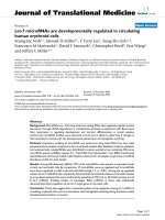
A. Return loss for the implantable antenna: muscle tissue
and heterogeneous medium
The simulated reflection loss of the Tx implantable
antenna in the homogeneous muscle tissue medium,
esophagus (scenario I), stomach (scenario II), small
intestine (scenario III), and the large intestine (scenario
IV) of the VFB as a function of frequency is shown in
Figure 3. At 2.45 GHz the antenna has an |S
11
|of
-29.21, -38, -29.7, -26.6, -31 dB in the homogeneous
muscle tissue, the esophagus, the stomach, the small
intestine and the large intestine of the VFB, respectively.
As the antenna is developed by only taking the dielectric
properties of the muscle tissue medium [7] into account,
variations in effective permittivity (insulation and the
medium) and wavelength in different tissues cause the
variation in |S
11
|. In particular, a shift of the resona nce
frequency of the antenna can be observed when placed
in different tissues, still the values of the |S
11
|inallthe
scenarios are below -10 dB in the complete ISM band
from 2.40 to 2.48 GHz and thus the antenna is suitable
for in-body propagation with an ohmic loss of 2.5%.
The input impedance of the implantable antenna in the
homogeneous muscle tissue at 2.45 GHz is Z(Ω)=49.9
- j3.4 whereas the input impedance of the implantable
Figure 2 Locations of Tx and Rx for various scenarios in the
VFB.
Kurup et al . EURASIP Journal on Wireless Communications and Networking 2011, 2011:51
/>Page 4 of 9
antenna in the stomach, small intestine, large intestine,
and esophagus of the VFB is equal to 53. 79 + j8.75,
51.63 - j3.9, 52.40 - j1.7, and 49.37 + j1.14, respective ly,
which is about 50 Ω, as desired.
B. Path loss
PLisdefinedastheratioofinputpoweratport1(P
in
)
to power received at port 2 (P
rec
) in a two-port setup.
PL in terms of transm ission coefficient is defined as 1/|
S
21
|
2
with respect to 50 Ω when the generator at the Tx
has an output impedance of 50 Ω and the Rx is termi-
nated with 50 Ω. This allows us to regard the setup as a
two-port circuit for which we determine |S
21
|
dB
with
reference impedances of 50 Ω at both ports:
PL|
dB
=(P
in
/P
rec
)=−10 log
1
0
|S
21
|
2
= −|S
21
|
dB
,
(1)
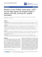
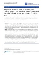
1) PL in human muscle tissue and heterogeneous VFB
Figure 4 compares the simulated PL in human m uscle
tissue and the 162 simulations for the heterogeneous
VFB as a function of distance d for the implanted
antenna. Figure 4 shows that the PL in the heteroge-
neous model which involves tissues with lower conduc-
tivities is lower than the PL in muscle tissue as in
scenario I (esophagus) and scenario II (stomach). PL is
seen to be larger in scenario III (small intestine) and
scenario IV (large intestine) which involves tissues with
higher conductivity as compared to the conductivity of
the homo geneous muscle tissue. The maximum PL at 8
cm is obtained for the small intestine and is 75.8 dB. In
the homogeneous muscle tissue the slope of the PL
remains constant, however in the heterogeneous scenar-
iostheslopeofthePLchangesastheantennamoves
from one tissue to another due to differences in the
dielect ric properties of the tissues through which the Rx
antenna traverses. For example, in Figure 4, a change in
the slope can be observed in the large intestine at a dis-
tance of 4 cm and 5 cm because the large intestine is
thin and hence the Rx moves out into a region occupied
by fat.
C. PL model
1) Homogeneous human muscle tissue
In this section the simulated results are used to develop
a PL model as a function of distance in human muscle
tissue at 2.45 GHz. The simu lated results and the fitted
model in human muscle tissue are shown in Figure 5.
The PL is modeled as follows [6]:
PL|
dB
=(10log
1
0
e
2
) α
1
d + C
1
|
dB
,
(2)
2 2.2 2.4 2.6 2.8
í40
í35
í30
í25
í20
í15
í10
í5
Frequenc
y
[GHz]
S
11
[dB]
Muscle
Small Intestine
Large Intestine
Esophagus
Stomach
Figure 3 Reflection loss of the implantable antenna in
homogeneous tissue and heterogeneous VFB.
10 20 30 40 50 60 70 8
0
10
20
30
40
50
60
70
80
d
[
mm
]
PL
[dB]
Homogeneous
Esophagus
Stomach
Small Intestine
Large Intestine
Figure 4 Path loss of the implantable antenna in the
homogeneous medium and in heterogeneous VFB.
10 20 30 40 50 60 70 8
0
20
25
30
35
40
45
50
55
60
6
5
d
[
mm
]
PL
[dB]
Muscle
Fit
Figure 5 PL in homogeneous muscle tissue and fitted model.
Kurup et al . EURASIP Journal on Wireless Communications and Networking 2011, 2011:51
/>Page 5 of 9
where the parameter a
1
is the attenuation constant
[
1
c
m
]
, C
1
|
dB
is a constant and their values are listed in
Table 2. 10 log
10
e
2
equals 8.68 dB and shows the expo-
nential behavior of the PL. The power decays exponen-
tially with respect to distance in a lossy medium similar
to the behavior of plane waves in lossy medium [16].
Since the fields exhibit an exponential decay in the med-
ium, the trend of the PL in Figure 5 shows an ex ponen-
tial behavior in accordance to the linear regression
equation (2).
2) Heterogeneous model for esophagus–scenario I
In this section the simulated results are used to develop
a PL model as a function of distance for the Tx placed
at the esophagus of the VFB at 2.45 GHz. The PL and
the fitted model are shown in Figure 6. In this scenario
the Rx antenna moves completely into the lungs at a
separatio n of 2 cm from the Tx antenna. Up to 2 cm
from Tx antenna a part of the Rx antenna moves in the
heart muscle (ε
r
=54.81ands = 2.25 S/m). Thus, a
change of slope is observed at 2 cm where the antenna
makes a transition from one tissue to another. This
same behavior is noticed in all the scenarios for hetero-
geneous media when the antenna makes a transition
from one tissue to another and can be observed very
well when there is a huge difference in the dielectric
properties. The PL is modeled as follows:
PL|
dB
=(10log
1
0
e
2
) α
2
d + C
2
|
dB
+ χ
2
|
dB
,
(3)
where the parameter a
2
is the effective attenuation
constant
[
1
c
m
]
, C
2
|
dB
is a constant and their values are
listed in Table 2. The effective attenuation constant is
the attenuation constant for all the tissues through
which the Rx antenna traverses through in each sce-
nario. The PL model is a linear regression model thus
consisting of a deterministic part which is a function of
distance and the random error term, c
2
|
dB
· c
2
|
dB
fol-
lows a zero mean normal distribution with a standard
deviation (SD), of 1. 31 dB. Figure 7 shows the Q-Q plot
of the empirical quantiles of the error between the PL
model and the simulated PL results on the vertical axis
to a theoretical standard normal distribution on the hor-
izontal axis in the esophagus of the VFB. A Q-Q plot is
a probability plot which compares t wo probability
distributions by plotting their quantiles against each
other. The points on the graph lay close to the straight
line suggesting that the data is normally distributed.
3) Heterogeneous model for stomach–scenario II
The PL of the simulated results for the three positions
in the stomach versus the distances and their fit is
shown in the Figure 8. At this position the Tx is placed
in the stomach (Figure 2) and the Rx is separ ated up to
adistanceof8cm.AstheRxmovesfromthestomach
of the VFB to the liver a slight change is observed in
the PL due to changes in the dielectric properties of the
tissues (between 2 and 3 cm (Figure 8)).
The PL is modeled as follows:
PL|
dB
=(10log
1
0
e
2
) α
3
d + C
3
|
dB
+ χ
3
|
dB
,
(4)
Table 2 Parameter values and SD of the fitted models for
PL
dB
in human muscle tissue and the heterogeneous
No. Scenario
α
i
(
1
c
m
)
C
i
(dB) SD (dB)
I Homogeneous muscle tissue 0.69 14.71 -
II VFB Esophagus 0.67 14.24 1.31
III VFB Stomach 0.68 13.40 1.22
IV VFB Small Intestine 0.89 12.36 2.25
V VFB Large Intestine 0.89 11.48 4.14
10 15 20 25 30 35 40 45 5
0
15
20
25
30
35
40
45
5
0
d
[
mm
]
PL
[dB]
Position 1
Position 2
Position 3
Fit
Figure 6 Path loss and the fitted model in esophagus.
í2.5 í2 í1.5 í1 í0.5 0 0.5 1 1.5 2 2.
5
í3
í2
í1
0
1
2
3
4
Standard Normal
Q
uantiles
Empirical
Q
uantiles of error
Figure 7 Q-Q plot of the empirical quantil es of error between
the simulated PL and the PL model versus the standard
normal quantiles in the esophagus.
Kurup et al . EURASIP Journal on Wireless Communications and Networking 2011, 2011:51
/>Page 6 of 9
where the parameter a
3
is the effective attenuation
constant
[
1
c
m
]
, C
3
|
dB
is a constant and their values are
listed in Table 2. c
3
|
dB
fol lows a zero mean normal dis-
trib ution with a SD of 1.22 dB. Figure 9 shows the Q-Q
plot of the empirical quantiles of the error between the
PL model a nd the simulated PL results on the vertical
axis to a theoretical standard normal distribution on the
horizontal axis in the stomach of the VFB. It can be
seen from the figure that they are in good agreement.
4) Heterogeneous model for small intestine–scenario III
In this section the simulated results are used to develop
a PL model as a function of distance for the Tx placed
at the intestine of the VFB at 2.45 GHz. In this scenario
the Rx antenna traverses through various tissues as
mentioned in Section III-A. The PL in the small
intestine at three different positions as a function of dis-
tance and the fitted model is shown in Figure 10. The
PL is modeled as follows:
PL|
dB
=(10log
1
0
e
2
) α
4
d + C
4
|
dB
+ χ
4
|
dB
,
(5)
where the parameter a
4
is the effective attenuation
constant
[
1
c
m
]
, C
4
|
dB
is a constant and their values are
listed in Table 2. c
4
|
dB
fol lows a zero mean normal dis-
tribution with a SD of 2.25 dB. Figure 11 shows the Q-
Q plot of the empirical quantiles of the error between
the PL mod el and the simulated PL results on the verti-
cal axis to a theoretical standard normal distribution on
the horizontal axis. Figure 11 shows that the empirical
distribution agrees very well with the normal
distribution.
5) Heterogeneous model for large intestine–scenario IV
Here the PL is modeled for the three positions of the Tx
in the large intestine as shown in Figure 12 and it can
be observed that the PL is h igh for a separation of 4
and 5 cm from the Tx antenna. At these distance the
Rx ante nna moves out of the large intestine into reg ion
of fat, thus increasing the PL. The PL is modeled as fol-
lows:
PL|
dB
=(10log
1
0
e
2
) α
5
d + C
5
|
dB
+ χ
5
|
dB
,
(6)
where the parameters a
5
is the effective attenuation
constant
[
1
c
m
]
, C
5
|
dB
is a constant and their values are
listed in Table 2. c
5
|
dB
fol lows a zero mean normal dis-
tribution with a SD of 4.14 dB.ThisSDislargerthan
other scenarios as the antenna traverses through the
large intestine, the fat and the dielectric properties of
the two have vast differences. Figure 13 s hows the Q-Q
plot of the empirical quantiles of the error between the
PL model a nd the simulated PL results on the vertical
10 20 30 40 50 60 70 8
0
10
20
30
40
50
60
7
0
d
[
mm
]
PL
[dB]
Position 1
Position 2
Position 3
Fit
Figure 8 Path loss and the fitted model in stomach.
í2.5 í2 í1.5 í1 í0.5 0 0.5 1 1.5 2 2.
5
í2
í1
0
1
2
3
4
5
Standard Normal
Q
uantiles
Empirical
Q
uantiles of error
Figure 9 Q-Q plot of the empirical quantil es of error between
the simulated PL and the PL model versus the standard
normal quantiles in the stomach.
10 20 30 40 50 60 70 8
0
10
20
30
40
50
60
70
80
d
[
mm
]
PL
[dB]
Position 1
Position 2
Position 3
Fit
Figure 10 Path loss and the fitted model in small intestine.
Kurup et al . EURASIP Journal on Wireless Communications and Networking 2011, 2011:51
/>Page 7 of 9
axis to a theoretical standard normal distribution on the
horizontal axis. It demonstrates that the empirical distri-
bution agrees very well with the normal distribution.
Discussion
Figure 14 shows the PL in the homogeneous medium,
the 95th percentile of the PL in heterog eneous VFB and
the PL samples from all the scenarios. The 95th percen-
tile is the value below which 95 percent of the PL values
maybefound.Weusethe95thpercentileasasafety
margin to account for the error term which is denoted
as c|
dB
in the PL model. From Figure 14 it can be seen
that the 95th percentile of the PL in heterogeneous VFB
lies above the PL in the homogeneous medium. Thus, if
we were to design an in-body WBAN with 95%
coverage, link budget calculations will be more conser-
vative than for the homogeneous medium and thus it is
very important to perform the s tudy of in-body WBAN
using heterogeneous models. Since it is difficult to carry
out measurements using heterogeneous medium, homo-
geneous medium can still be used for validation and
equipment testing. However simulations using heteroge-
neous models will provide more conservative models for
PL.
Table 2 lists all the a ttenuation constants a
i
, the con-
stant C|
dB
and the SD from all the scenar ios considered.
It can be seen for the two s cenarios of small intestine
and large intestine the effective attenuation constants
are higher than the attenuation constant of the homoge-
neous muscle tissue. The conductivity, s =3.17S/mof
í2.5 í2 í1.5 í1 í0.5 0 0.5 1 1.5 2 2.5
í6
í4
í2
0
2
4
6
Standard Normal
Q
uantiles
Empirical
Q
uantiles of error
Figure 11 Q-Q plot of the empirical quantiles of error between
the simulated PL and the PL model versus the standard
normal quantiles in the small intestine.
10 20 30 40 50 60 70 8
0
10
20
30
40
50
60
70
80
d
[
mm
]
PL
[dB]
Position 1
Position 2
Position 3
Fit
Figure 12 Path loss and the fitted model in large intestine.
í2.5 í2 í1.5 í1 í0.5 0 0.5 1 1.5 2 2.5
í10
í5
0
5
10
15
Standard Normal
Q
uantiles
Empirical
Q
uantiles o
f
error
Figure 13 Q-Q plot of the empirical quantiles of error between
the simulated PL and the PL model versus the standard
normal quantiles in the large intestine.
10 20 30 40 50 60 70 8
0
10
20
30
40
50
60
70
80
90
d
[
mm
]
PL [dB]
Homogeneous
95
th
percentile Esophagus
95
th
percentile Stomach
95
th
percentile Small Intestine
95
th
percentile Large Intestine
Simulation results
Figure 14 Path loss of the implantable antenna in the
homogeneous medium and in heterogeneous VFB.
Kurup et al . EURASIP Journal on Wireless Communications and Networking 2011, 2011:51
/>Page 8 of 9
the small intestine is much higher than the conductivity,
s = 2.01 S/m, of the muscle tissue causing more atten-
tuation in the small intestine. In this scenario the Rx
antenna traverses through various tissues such as th e
kidney (ε
r
= 52.74 and s =2.43S/m),gallbladder(ε
r
=
68.36 and s =2.8S/m),liver(ε
r
= 54.81 and s =2.25
S/m), and also the artery (ε
r
= 58.26 and s =2.54S/m).
The tissues through which the antenna passes through
have the conductivity higher as compared to the muscle
tissue. In the large intestine the huge variation in the
dielectric properties of the tissues (large intestine and
the fat layer) through which the Rx traverses gives rise
to higher attenuat ions. In case of the esophagus and the
stomach, Table 2 shows that the effective attenuation
constant lower than the muscle tissue medium as in
both the scenario the Rx antenna traverses through tis-
sues having lower conductivities compared to the mus-
cle tissue. In case of the esophagus the tissues are
esophagus (ε
r
= 62.15 and s =2.2S/m)andlungs(ε
r
=
34.42 and s = 1.24 S/m). In case of stomach the
antenna traverses through the stomach lumen ((ε
r
=
52.72 and s = 1.74 S/m).
Conclusions
The path loss in homogeneous human muscle tissue and
various heterogeneous media using implantable slot
dipole conformal flexible antennas is investigated at 2.45
GHz. An in-body path loss model for the homogeneous
medium and a heterogeneous human model is derived.
Simulations based on FDTD and the fitted models show
excellent agreement. It is observed from the considered
scenarios, that the 95th percentile of the PL in heteroge-
neous VFB lies above the PL in the homogeneous med-
ium. Thus, PL model in the heterogeneous VFB will
help in understanding the power req uirements for
implants working at 2.45 GHz. The PL model in the
heterog eneous human model for the cons idered deep
tissue implant scenarios can also be us ed to evaluate the
performance of in-b ody WBAN systems using well spe-
cified setups and to carry out link budget calculations.
Abbreviations
CPW: coplanar waveguide; ERC: European Radiocommunications Committee;
FDTD: finite-difference time-domain; ICDs: implantable cardioverter
defibrillators; ISM: industrial: scientific: and medical; MRI: magnetic resonance
images; PL: path loss; PDMS: polydimethylsiloxane; Rx: receiver; SRD: short
range device; SD: standard deviation; Tx: transmitter; WBAN: wireless body
area network.
Author details
1
Department of Information Technology, WiCa, Ghent University/IBBT,
Gaston Crommenlaan 8 Box 201, 9050 Ghent, Belgium
2
Department of
Information Technology, Electromagnetics Group, Ghent University, Sint-
Pietersnieuwstraat 41, 9000 Gent, Belgium
3
Ghent University, ELINTEC-TFCG
Technologiepark 914, 9052 Gent, Belgium
Competing interests
The authors declare that they have no competing interests
Received: 18 October 2010 Accepted: 3 August 2011
Published: 3 August 2011
References
1. B Latre, G Vermeeren, I Moerman, L Martens, SDF Louagie, P Demeester,
Networking and propagation issues in body area networks. IEEE 11th
Symposium on Communications and Vehicular Technology in the Benelux
2004, SCVT 2004, November 2004 (CD-ROM)
2. A Alomainy, Y Hao, Modeling and characterization of biotelemetric radio
channel from ingested implants considering organ contents. Antennas and
Propagation, IEEE Transactions. 57, 999–1005 (April 2009)
3. SKS Gupta, Y Prakash, E Elsharawy, L Schwiebert, Towards a propagation
model for wireless biomedical applications. IEEE International Conference on
Communications. 3, 1993–1997 (May 2003)
4. A Johansson, Wireless communication with medical implants (Ph.D.
dissertation, Lund University, 2004)
5. K Ito, Wei Xia, Masaharu Takahashi, K Saito, An Implanted Cavity Slot
Antenna for Medical Communication Systems, in 3rd European Conference
on Antennas and Propagation (EuCAP), Berlin, Germany. 718–721 (March
2009)
6. D Kurup, W Joseph, G Vermeeren, L Martens, Path loss model for in-body
communication in homogeneous human muscle tissue. IET Electronics
Letters, 453–454 (April 2009)
7. M Scarpello, D Kurup, H Rogier, D Vande Ginste, F Axisa, J Vanfleteren, W
Joseph, L Martens, G Vermeeren, Design of an implantable slot dipole
conformal flexible antenna for biomedical applications. Submitted to IEEE
Transactions on Antennas and Propagation (2010)
8. B Barth, K Donovan, V Fox, Endoscopic placement of the capsule
endoscope in children. Gastrointestinal Endoscopy. 60, 818–821
(November 2004). doi:10.1016/S0016-5107(04)02052-8
9. E Seidman, M Dirks, Capsule endoscopy in the pediatric patient. Current
Treatment Options Gastroenterol. 9, 416–22 (September 2006). doi:10.1007/
BF02738531
10. H Kavin, J Berman, T Martin, A Feldman, K Forsey-Koukol, Capsule
endoscopy for a 2.5-year-old child: Obscure gastrointestinal bleeding from
mixed, juvenile, capillary hemangioma-angiomatosis of the jejunum.
Pediatrics. 117, 539–543 (February 2006). doi:10.1542/peds.2005-0710
11. M Thomson, A Fritscher-Ravens, S Hall, N Afzal, P Ashwood, C Swain,
Endoluminal gastroplication in children with significant gastro-oesophageal
reflux disease. Gut. 53, 1745–50 (April 2004). doi:10.1136/gut.2004.041921
12. FCC OET Bulletin 65, Revised Supplement C, Evaluating Compliance with
FCC Guidelines for Human Exposure to Radiofrequency Electromagnetic
Fields. Federal Communication Commission, Office of Engineering and
Technology (June 2001)
13. European Radiocommunications Committee, ERC recommendations 70-03
relating to the use of short range devices (SRD), in Eur. Postal
Telecommunications Administration Conf., CEPT-ERC 70-03, Annex 12,
Tromso, Norway, (1997)
14. C Gabriel, S Gabriel, Compilation of the dielectric properties of body tissues
at RF and microwave frequencies. Tech. Rep. AL/OE-RE-1996-0037. http://
niremf.ifac.cnr.it/docs/DIELECTRIC/home.html (1996)
15. SPEAG-Schmid and Partner Engineering AG, Reference manual for the
semcad simulation platform for electromagnetic compatibility, antenna
design and dosimetry, (2001)
16. SJ Orfanidis, Electromagnetic Waves and Antennas, gers.
edu/~orfanidi/ewa/ (2008)
doi:10.1186/1687-1499-2011-51
Cite this article as: Kurup et al.: In-body path loss models for implants
in heterogeneous human tissues using implantable slot dipole
conformal flexible antennas. EURASIP Journal on Wireless Communications
and Networking 2011 2011:51.
Kurup et al . EURASIP Journal on Wireless Communications and Networking 2011, 2011:51
/>Page 9 of 9