Laser Pulse Phenomena and Applications Part 2 doc
Bạn đang xem bản rút gọn của tài liệu. Xem và tải ngay bản đầy đủ của tài liệu tại đây (1.26 MB, 30 trang )
"Impulsar": New Application for High Power High Repetition Rate Pulse-Periodic Lasers
21
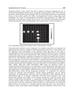
Fig. 2. Oscillograms of the laser pulse (1) and radiation pulse transmitted through the OPD
(2) for f=50 kHz.
attachment) was mounted on the chamber end. Laser radiation was directed to the chamber
through a lens with a focal distance of 17 cm. The argon jet was formed during flowing from
a high-pressure chamber through a hole of diameter ~ 3 – 4 mm. The jet velocity V was
controlled by the pressure of argon, which was delivered to the chamber through a flexible
hose. The force produced by the jet and shock waves was imparted with the help of a thin
(of diameter ~ 0.2 mm) molybdenum wire to a weight standing on a strain-gauge balance
(accurate to 0.1 g). The wire length was 12 cm and the block diameter was 1 cm.
The sequence of operations in each experiment was as follows. A weight fixed on a wire was
placed on a balance. The model was slightly deviated from the equilibrium position (in the
block direction), which is necessary for producing the initial tension of the wire (~ 1 g). The
reading F
m
of the balance was fixed, then the jet was switched, and the reading of the
balance decreased to F
1
. This is explained by the fact that the rapid jet produces a reduced
pressure (ejection effect) in the reflector. After the OPD switching, the reading of the balance
became F
2
. The propulsion F
r
produced by the OPD is equal to F
1
- F
2
. The pressure of shock
waves was measured with a pressure gauge whose output signal was stored in a PC with a
step of ~ 1 µs. The linearity band of the pressure gauge was ~ 100 kHz. The gauge was
located at a distance of ~ 5 cm from the jet axis (see Figure 1) and was switched on after the
OPD ignition (t = 0). The pressure was detected for 100 ms.
Let us estimate the possibility of shock-wave merging in the experiment and the expected
values of F
r
and J
r
. The merging efficiency depends on the parameters ω=fR
d
/C
0
and M
0
=
V/C
0
(M
0
< 1), where C
0
is the sound speed in gas. If the distance from the OPD region to the
walls is much larger than R
d
and sparks are spherical or their length l is smaller than R
d
,
then the frequencies characterizing the interaction of the OPD with gas are:
Laser Pulse Phenomena and Applications
22
For ω<ω
1
, the shock waves do not interact with each other. In the range ω<ω
1
<ω
2
, the
compression phases of the adjacent waves begin to merge, this effect being enhanced as the
value of ω approaches ω
2
.
In the region ω<ω
2
, the shock waves form a quasi-stationary wave
with the length greatly exceeding the length of the compression phase of the shock waves.
For ω<ω
0
, the OPD efficiently (up to ~ 30 %) transforms repetitively pulsed radiation to
shock waves.
In the pulsed regime the value of M
0
in (1) corresponds to the jet velocity. Because shock
waves merge in an immobile gas, M
0
≈ 0 in (2) and (3). The frequencies f=7-100 kHz
correspond to R
d
= 0.88 - 0.55 cm and ω = 0.2 - 1.7. Therefore, shock waves do not merge in
this case. In trains, where the energy of the first pulses is greater by a factor of 1.5-2 than that
of the next pulses (ω≈2), the first shock waves can merge. The propulsion produced by
pulse trains is F
r
= J
r
ηW = 0.3 N (~ 30 g), where-J
r
= 1.1 N kW
-1
, η = 0.6, and W~ 0.5 kW.
In the stationary regime for M
0
~ 0.7, the shock wave merge because ω>ω
2
(ω = 1.8, ω
2
≈ 1.3).
A quasi-stationary wave is formed between the OPD and the cylinder bottom. The excess
pressure on the bottom is δP = P-P
0
= 0.54P
0
(R
d
/r)
1.64
≈ 0.25- 0.5 atm, and the propulsion is F
r
≈ π(D
r
2
– D
j
2
)δP/4 = 0.03- 0.06kg.
Fig. 3. Pressure pulsations produced by the OPD for V=300 ms
-1
without reflector), f=7 kHz,
W=690 W (a); f=100 kHz, W= 1700 W (b), and f=100 kHz, the train repetition rate φ=1 kHz,
W=1000 W, the number of pulses in the train N=30 (c); the train of shock waves at a large
scale, parameters are as in Fig. 3c (d).
"Impulsar": New Application for High Power High Repetition Rate Pulse-Periodic Lasers
23
3. Results of measurements
3.1 Control measurements
The jet propulsions F
j
and F
r
and the excess pulsation pressure δP = P - P
0
were measured
for the model without the reflector. We considered the cases of the jet without and with the
OPD. The jet velocity V and radiation parameters were varied. For V= 50, 100, and 300 m s
-
1
, the propulsion produced by the jet was Fj = 6, 28, and 200 g, respectively, and the
amplitude of pulsations was δP = 5×10
-6
, 2×10
-5
and 3×10
-4
atm. The OPD burning in the jet
did not change the reading of the balance. This is explained by the fact that the OPD is
located at a distance of r from the bottom of a high-pressure chamber, which satisfies the
inequality r/R
d
> 2, when the momentum produced by shock waves is small [3, 22]. As
follows from Fig. 3, pulsations δP(t) produced by the OPD greatly exceed pressure
fluctuations in the jet.
3.2 Stationary regime
The OPD was burning in a flow which was formed during the gas outflow from the
chamber through a hole (D
j
= 0.3 cm) to the reflector (D
r
= 0.5 cm) (Figure 4). Because the
excess pressure on the reflector bottom was ~ 0.5 atm (see above), to avoid the jet closing,
the pressure used in the chamber was set equal to ~ 2 atm. The jet velocity without the ODP
was V=300 and 400 ms
-1
, F
j
= 80 and 140 g. The OPD was produced by repetitively pulsed
radiation with f= 50 and 100 kHz and the average power W≈1200 W (the absorbed power
was W
a
≈ 650 W). Within several seconds after the OPD switching, the reflector was heated
up to the temperature more than 100°C.
Figure 5 illustrates the time window for visualization of shock waves with the Schlieren
system in the presence of plasma. Before 7 μs, the plasma is too bright relative to the LED
source, and all information about the shock wave is lost. At 7 μs, the shock wave image could
be discerned under very close examination. By 10 μs, the shock wave is clearly visible in the
image; however, at this time the shock wave has nearly left the field of view. A technique was
needed to resolve the shock waves at short timescales, when plasma was present.
Fig. 4. Reflector of a stationary laser engine: (1) repetitively pulsed laser radiation with f=50
and 100 kHz, W=1200 W; (2) OPD; (3) reflector; (4) hole of diameter ~ 3 mm through which
argon outflows from a high-pressure chamber (~ 2atm) to the reflector; (5) reflector bottom,
the angle of inclination to the axis is ~ 30º.
Laser Pulse Phenomena and Applications
24
For f= 50 kHz and V= 300 m s
-1
, the propulsion is F
r
= 40 g, and for V= 400 m s
-1
the
propulsion is 69 g; the coupling coefficient is J
r
≈ 1.06 N kW
-1
. The propulsion F
r
is stationary
because the criteria for shock-wave merging in front of the OPD region are fulfilled.
Downstream, the shock waves do not merge. One can see this from Figure 5 demonstrating
pressure pulsations δP(t) measured outside the reflector. They characterize the absorption of
repetitively pulsed radiation in the OPD and, therefore, the propulsion. For f= 50 kHz, the
instability is weak (±5 %) and for f= 100 kHz, the modulation δP(t) is close to 100 %. The
characteristic frequency of the amplitude modulation f
a
≈ 4 kHz is close to C
0
/(2H), where H
is the reflector length. The possible explanation is that at the high frequency f the plasma has
no time to be removed from the OPD burning region, which reduces the generation
efficiency of shock waves. The jet closing can also lead to the same result if the pressure in
the quasi-stationary wave is comparable with that in the chamber. Thus, repetitively pulsed
radiation can be used to produce the stationary propulsion in a laser engine.
Fig. 5. Pressure pulsations δP produced upon OPD burning in the reflector with D
r
=0.5 cm,
H=4/6 cm, V=400 m s
-1
, D
j
=0/3 cm for f=50 kHz, W=1300 W (a) and f=100 kHz, W=1200 W
(b, c).
"Impulsar": New Application for High Power High Repetition Rate Pulse-Periodic Lasers
25
3.3 Pulsed regime
To find the optimal parameters of the laser engine, we performed approximately 100 OPD
starts. Some data are presented in Table 1. We varied the diameter and length of the
reflector, radiation parameters, and the jet velocity (from 50 to 300 m s
-1
). For V= 50 m s
-1
the ejection effect is small, for V= 300 m s
-1
≈C
0
, this effect is strong, while for V≈ 100 ms
-1
,
the transition regime takes place. In some cases, the cylinder was perforated along its
circumference to reduce ejection. The OPD was produced by radiation pulse trains, and in
some cases – by repetitively pulsed radiation. The structure and repetition rate of pulse
trains was selected to provide the replacement of the heated OPD gas by the atmospheric
air. The train duration was ~ 1/3 of its period, the number of pulses was N = 15 or 30,
depending on the frequency f. The heating mechanism was the action of the thermal
radiation of a plasma [23], the turbulent thermal diffusivity with the characteristic time ~
300 µ
S [24] and shock waves.
The propulsion F
r
was observed with decreasing the reflector diameter and increasing its
length. The OPD burned at a distance of ~ 1 cm from the reflector bottom. One can see from
Figure 6 that the shock waves produced by the first high-power pulses in trains merge. For
f= 100 kHz, the pulse energy is low, which is manifested in the instability of pressure
pulsations in trains. As the pulse energy was approximately doubled at the frequency f = 50
kHz, pulsations δP (t) were stabilized. The OPD burning in the reflector of a large diameter
(D
r
/R
d
≈ 4) at a distance from its bottom satisfying the relation r/R
d
≈ 3 did not produce the
propulsion.
Fig. 6. Pressure pulsations δP in the OPD produced by pulse trains with φ=1.1 kHz, f=50
kHz, W=720 W, N=15, V=300 m s
-1
, D
r
=1.5 cm, H= 5 cm, D
j
= 4 mm, and F= 4.5 g.
Table 1 presents some results of the measurements. One can see that the coupling coefficient
J
r
strongly depends on many parameters, achieving 1 N kW
-1
in the stationary regime and
0.53 N kW
-1
in the pulsed regime.
At present, the methods of power scaling of laser systems and laser engines, which are also
used in laboratories, are being extensively developed [10, 25]. Let us demonstrate their
Laser Pulse Phenomena and Applications
26
application by examples. We observed the effect when the OPD produced the 'negative'
propulsion F
t
= -97 g (see Table 1), which correspond to the deceleration of a rocket. The
value of J
r
can be increased by approximately a factor of 1.5 by increasing the pulse energy
and decreasing their duration down to ~ 0.2 µs. An important factor characterizing the
operation of a laser engine at the high-altitude flying is the efficiency I
m
of the used working
gas. The value I
m
= 0.005 kg N
-1
s
-1
can be considerably reduced in experiments by using a
higher-power radiation. The power of repetitively pulsed radiation should be no less than
10 kW. In this case, F
r
will considerably exceed all the other forces. The gas-dynamic effects
that influence the value of.F
r
, for example, the bottom resistance at the flight velocity ~ l km
s
-1
should be taken into account.
Table 1. Experimental conditions and results.
Note. Laser radiation was focused at a distance of 1 cm from the reflector bottom; * six holes
of diameter 5 mm over the reflector perimeter at a distance of 7 mm from its exhaust; **six
holes of diameter 5 mm over the reflector perimeter at a distance of 15 mm from its exhaust.
Thus, our experiments have confirmed that repetitively pulsed laser radiation produces the
stationary propulsion with the high coupling coefficient. The development of the scaling
methods for laser systems, the increase in the output radiation power and optimization of
the interaction of shock waves will result in a considerable increase in the laser-engine
efficiency.
4. The impact of thermal action
A laser air-jet engine (LAJE) uses repetitively pulsed laser radiation and the atmospheric air
as a working substance [1-3]. In the tail part of a rocket a reflector focusing radiation is
located. The propulsion is produced due to the action of the periodic shock waves
produced by laser sparks on the reflector. The laser air-jet engine is attractive due to its
simplicity and high efficiency. It was pointed out in papers [26] that the LAJE can find
applications for launching space crafts if ~ 100-kJ repetitively pulsed lasers with pulse
repetition rates of hundreds hertz are developed and the damage of the optical reflector
"Impulsar": New Application for High Power High Repetition Rate Pulse-Periodic Lasers
27
under the action of shock waves and laser plasma is eliminated. These problems can be
solved by using high pulse repetition rates (f~ 100 kHz), an optical pulsed discharge, and
the merging of shock waves [12, 13]. The efficiency of the use of laser radiation in the case
of short pulses at high pulse repetition rates is considerably higher. It is shown in this paper
that factors damaging the reflector and a triggered device cannot be eliminated at low pulse
repetition rates and are of the resonance type.
Let us estimate the basic LAJE parameters: the forces acting on a rocket in the cases of
pulsed and stationary acceleration, the wavelength of compression waves excited in the
rocket body by shock waves, the radius R
k
of the plasma region (cavern) formed upon the
expansion of a laser spark. We use the expressions for shock-wave parameters obtained by
us. A laser spark was treated as a spherical region of radius r
0
in which the absorption of
energy for the time ~ 1 µ
S is accompanied by a pressure jump of the order of tens and
hundreds of atmospheres. This is valid for the LAJE in which the focal distance and
diameter of a beam on the reflector are comparable and the spark length is small. The
reflector is a hemisphere of radius R
r
. The frequency f is determined by the necessity of
replacing hot air in the reflector by atmospheric air.
Let us estimate the excess of the peak value F
m
of the repetitively pulsed propulsion over the
stationary force F
s
upon accelerating a rocket of mass M. It is obvious that F
s
= Ma, where the
acceleration a = (10-20)g
0
≈ 100 - 200 m s
-2
. The peak value of the repetitively pulsed propulsion
is achieved when the shock wave front arrives on the reflector. The excess pressure in the
shock wave (with respect to the atmospheric pressure P
0
) produces the propulsion F
j
(t) and
acceleration a of a rocket of mass M. The momentum increment produced by the shock wave is:
(4)
Here, F
a
is the average value of the propulsion for the time t
a
of the action of the
compression phase of the shock wave on the reflector, and F
m
≈ 2F
a
. By equating δ
Pi
to the
momentum increment δp
s
= F/f= aM/f over the period under the action of the stationary
propulsion F
s
, we find:
(5)
The value of ∆, as shown below, depends on many parameters. The momentum increment
per period can be expressed in terms of the coupling coefficient J as δ
Pi
= JQ, where Q [J] is
the laser radiation energy absorbed in a spark. The condition δ
Pi
= δp
s
gives the relation:
(6)
between the basic parameters of the problem: W = Qf is the absorbed average power of
repetitively pulsed radiation, and J ≈ 0.0001 - 0.0012 N s J
-1
[3, 13, 26].
The action time of the compression phase on the reflector is t
a
~ R
c
/V, where V≈ k
1
C
0
is the
shock-wave velocity in front of the wall (k
1
~ 1.2) and C
0
≈ 3.4 × 10
4
cm s
-1
is the sound speed
in air. The length R
c
of the shock wave compression phase can be found from the relation:
(7)
Laser Pulse Phenomena and Applications
28
Here, h is the distance from the spark centre to the reflector surface and R
d
≈ 2.15(Q/P
0
)
1/3
is
the dynamic radius of the spark (distance at which the pressure in the shock wave becomes
close to the air pressure P
0
). In this expression, R
d
is measured in cm and P
0
in atm. The
cavern radius can be found from the relation:
(8)
The final expression (8) corresponds to the inequality r
0
/R
d
< 0.03 – 0.1, which is typical for
laser sparks (r
0
is their initial radius). Let us find the range of P
0
where the two conditions
are fulfilled simultaneously: the plasma is not in contact with the reflector surface and the
coupling coefficient J is close to its maximum [3, 22, 26]. This corresponds to the inequality
R
k
<h<R
d
. By dividing both parts of this inequality by R
d
, we obtain R
k
/R
d
< h/R
d
< 1, or 0.25 <
h/R
d
< 1. As the rocket gains height, the air pressure and, hence, h/R
d
decrease. If we assume
that at the start (P
0
= 1 atm) the ratio h/R
d
= 1, where h and R
d
are chosen according to (2),
then the inequality 0.25 < h/R
d
< 1 is fulfilled for P
0
= 1 – 0.015 atm, which restricts the flight
altitude of the rocket by the value 30 - 40 km (h = const).
The optimal distance h satisfies the relation h/R
d
≈ 0.25b
i
where b
i
≈ 4 - 5. By substituting h/R
d
into (7), we find the length of the shock-wave compression phase and the time of its action
on the reflector:
(9)
(10)
Where s
1
=0.37b
i
0.32
/(k
1
C
0
)≈9×10
-6
b
i
0.32
. From this, by using the relation ∆=F
m
/F
a
=2/(Ft
a
) we
find:
(11)
Of the three parameters Q, W, and f, two parameters are independent. The third parameter
can be determined from expression (6). The conditions l/f~t
a
and ∆ ≈ 1 – 2 correspond to the
merging of shock waves [12].
The important parameters are the ratio of t
a
to the propagation time t
z
= L/C
m
of sound over
the entire rocket length L (C
m
is the sound speed in a metal) and the ratio of t
z
to 1/f. For steel
and aluminum, C
m
= 5.1 and 5.2 km s
-1
, respectively. By using (10), we obtain:
(12)
Here, L is measured in cm and C
m
in cm s
-1
. Expression (12) gives the energy:
"Impulsar": New Application for High Power High Repetition Rate Pulse-Periodic Lasers
29
(13)
From the practical point of view, of the most interest is the case U> 1, when the uniform
load is produced over the entire length L. If U< 1, the acceleration is not stationary and the
wavelength of the wave excited in the rocket body is much smaller than L. If also C
m
/f < L,
then many compression waves fit the length L. The case U≈ 1 corresponds to the resonance
excitation of the waves. Obviously, the case U≤ 1 is unacceptable from the point of view of
the rocket strength.
By using the expressions obtained above, we estimate ∆, U, and R
k
for laboratory
experiments and a small-mass rocket. We assume that b
i
=
4, J=5×10
-4
N s J
-1
, and s
1
= 1.4×10
-
5
. For the laboratory conditions, M ≈ 0.1 kg, R
r
≈ 5 cm, L= 10 cm, and a = 100 m s
-2
. The
average value of the repetitively pulsed propulsion F
1P
is equal to the stationary propulsion,
F
IP
= F
s
= 10 N; the average power of repetitively pulsed radiation is W=F
IP
/J = 20 kW, and
the pulse energy is Q
p
= W/f. We estimate the frequency f and, hence, Q
p
≈ Q for the two
limiting cases.
At the start, P
0
≈ 1 atm and the cavern radius R
k
is considerably smaller than R
r
. Here, as in the
unbounded space, the laser plasma is cooled due to turbulent thermal mass transfer. For Q
p
<
20 J, the characteristic time of this process is 2-5 ms [8,9], which corresponds to f = 500 – 200
Hz. If R
k
~R
r
(P
0
< 0.1 atm), the hot gas at temperature of a few thousands of degrees occupies
the greater part of the reflector volume. The frequency f is determined by the necessity of
replacing gas over the entire volume and is ~ 0.5C
0
/R
r
-850 Hz. Let us assume for further
estimates that f = 200 Hz, which gives Q
p
= 100 J. We find from (7) and (8) that ∆ = 74 and U =
3.5. This means that the maximum dynamic propulsion exceeds by many times the propulsion
corresponding to the stationary acceleration. The action time of the shock wave is longer by a
factor of 3.5 than the propagation time of the shock wave over the model length. For P
0
= 1
and 0.01 atm, the cavern radius is R
k
= 2.5 and 11.6 cm, respectively.
5. The dynamic resonance loads
Let us make the estimate for a rocket by assuming that M ≈ 20 kg, R
r
≈ 20 cm, L = 200 cm,
and a = 100 m s
-2
. The average repetitively pulsed propulsion is F
IP
= F
S
= 2000 N, the
average radiation power is W=4MW, for f= 200 Hz the pulse energy is Q
p
= 20 kJ, ∆ = 12.6, U
= 1, R
k
= 14.7 and 68 cm (P
0
= 1 and 0.01 atm), and F
m
= 25.6 kN = 2560 kg. One can see that
the repetitively pulsed acceleration regime produces the dynamic loads on the rocket body
which are an order of magnitude greater than F
s
. They have the resonance nature because
the condition U ~ 1 means that the compression wavelengths are comparable with the rocket
length. In addition, as the rocket length is increased up to 4 m and the pulse repetition rate
is increased up to 1 kHz, the oscillation eigenfrequency C
m
/L of the rocket body is close to f
(resonance).
Thus, our estimates have shown that at a low pulse repetition rate the thermal contact of the
plasma with the reflector and strong dynamic loads are inevitable. The situation is
aggravated by the excitation of resonance oscillations in the rocket body. These difficulties
can be eliminated by using the method based on the merging of shock waves. Calculations
and experiments [28] have confirmed the possibility of producing the stationary propulsion
by using laser radiation with high laser pulse repetition rates. The method of scaling the
output radiation power is presented in [10].
Laser Pulse Phenomena and Applications
30
6. Matrix of reflectors
This matrix consists of N-element single reflectors, pulse-periodic radiation with a repetition
rate of 100 kHz, pulse energy q and average power WC. All elements of the matrix are very
similar (Figure 7), radiation comes with the same parameters: qm = q / N, W
m
= W
C
/ N. The
matrix of reflectors creates a matrix of OPD, each one is stabilized by gas flux with velocity -
V
Jm
. OPD’s have no interactions in between. Elements structure of the matrix of reflectors
could help find the solution for better conditions of gas flux penetration. In our case the
number of reflectors was N = 8. Larger values of N are not reasonable.
The following estimations are valid for the boundary conditions: W
C
= 20 MW (W
m
= 2.5
MW), f = 105 Hz, q = 200J (q
m
= 25J), a
rm
= 0.3. Index 1 is for – P0 = 1 atm. (Start of
“Impulsar”) and index 2 for P
0
= 0.1 аtm. (end of regime).
Radius of cylinder for each reflector
()
13
2
12 12 13
0.43
0.2
15.5
mJm
dJm
r
rm
mm
qP
R
R
Rcm
N
δδ
== ==
Focus of reflector ~ 5 сm. The size of matrix ~ 90 сm. Additional pressure is:
δ
P
m1
= 1.56 atm. and
δ
P
m2
= 0.55 atm.
Force acting on matrix:
F
am1
= 100⋅103 N, F
am2
= 35.6⋅103 N.
Specific force for each element of the matrix (for MW of average power):
J
m1
≈ 4000 N/MW, J
m2
≈1500 N/MW.
The velocities of gas flux in the reflectors of matrix:
V
J1
= 2520 m/s, V
J2
= 5440 m/s
Flight control in this case can be done by thrust change for the different elements of the
matrix of reflectors. At the same time, such a configuration could be very helpful in the
realization of efficient gas exchange in the area of breakdown behind of the reflectors
(Figure 7).
Thus, an OPD can be stationary or move at a high velocity in a gaseous medium. However,
stable SW generation occurs only for a certain relation between the radiation intensity, laser
pulse repetition rate, their filling factor, and the OPD velocity. The OPD generates a QSW in
the surrounding space if it is stationary or moves at a subsonic velocity and its parameters
satisfy the aforementioned conditions. The mechanism of SW merging operates in various
media in a wide range of laser pulse energies. The results of investigations show that the
efficiency of the high repetition rate pulse-periodic laser radiation can be increased
substantially when a QSW is used for producing thrust in a laser engine [13, 14].
7. Super long conductive canal for energy delivery
Powerful lasers are capable to create the spending channels of the big length which are
settling down on any distances from a radiator. At relatively small energies of single
"Impulsar": New Application for High Power High Repetition Rate Pulse-Periodic Lasers
31
Fig. 7. “Impulsar” engine scheme based on QSW. А) Focusing system, Б) – OPD matrix,
creating flat QSW; В) Plasma created inhomogeneities; 1) OPD elements; 1’) Model of OPD
(Distance from 1’ to 4: less 10 сm); 2) Flat QSW, (P – P0)/P0 ≈ 0.5 – 3; 2’) Radial QSW, (P –
P0)/P0 < 0.1; 3) Main beam, q ~ 100 J; 3’ – focused beams q ~ 3-5J, creating QSW matrix; 4)
Matrix of focusing elements and air injecting system; 5) OPD matrix of plasma decay; 5’)
OPD plasma turbulence ; 6) Gas flow; 7) Nozzle.
impulses the lengths of channels make about hundreds of meters. Since 1970 the successful
attempts of their usage were undertaken for solution of problems of interception of
lightning and blocking of overload waves on electric lines. The traditional lightning
protection systems being used currently are not always in a position to ensure the desired
level of efficiency. This stimulates the quest for new approaches to solve this problem. Laser
protection against lightning is one of the most prospective trends that are being developed
actively at present [29,30].
. While using this approach, it is assumed that the lightning discharge channel being
developed is guided towards the conventional rod of the metal lightning rod along the
plasma channel formed as a result of the laser induced breakdown of the atmosphere. This
method is based on the concept of an active lightning rod, when a laser beam can be used
for “triggering” and guiding a positive ascending leader from the tip of a lightning rod to a
negatively charged thunderstorm cloud. It is expected that in contrast to the traditional
approach, the use of laser spark will make it possible to control efficiently the very process
of protection from lightning, ensure the selectivity of lightning capture, and provide safety
of tall objects and large areas. Conductive canal in this case is about 10-15m long and main
advantage of the approach is due to immediate appearance of laser produced prolongation
of the lightning rod. But maximum length of the laser produced breakdown in the air was
registered on the level of 100m and limited by optical method of laser energy delivery into
the focal point. Where is the way to get conductive canal of much longer length?
Laser Pulse Phenomena and Applications
32
The same goal to produce long conductive canal has ongoing French-German program
“Teramobile”, based on femto - second multi-photon lasers technology. But the goal is to get
very long canal with very low level of electrical resistivity in comparison with canals
produced by infrared laser radiation breakdown. The ionisation of air, produced by ultra-
intense and ultra-short pulse can be put to use to channel bolts of lightning. As a
“Teramobile” burst propagates it creates a sort of straight filament of ionised air, which
should conduct electricity. If the laser were directed toward a dark and threatening
thunderhead, it would trigger a lightning bolt that could be safely pushed away from doing
harm. This capacity has already been demonstrated over a distance of a few meters only
with a laboratory version of lightning, and tests on a more natural scale are limited by very
high filaments resistivity. So what do we do with a mobile terawatt laser, if it is not good
enough for the lightning control ? It can be used very effectively to study the propagation of
intense laser light in the atmosphere, detect pollution, and control the parameters of fast
objects in the space. Ultra - high intensity brings its own special qualities; it modifies
significantly the index of refraction while it induces a focusing of the light beam along its
path, the effect of the latter being to produce a self - guiding laser burst which can travel
hundreds of meters. Another effect is that the luminous spectrum widens to yield a white
laser whose light is composed of a wide range of wavelengths, which is important for a
wide spectrum of applications.
There upon the well known program of creation of “Impulsar” represents a great interest, as
this program in a combination with high-voltage high - frequency source can be useful in
the solution of above mentioned problems. The principle of “Impulsar” operation can be
shortly described as follows [31].
Jet draught of the offered device is made under influence of powerful high frequency pulse-
periodic laser radiation. In the experiments the CO2 laser and solid - state Nd YAG laser
systems were used. Active impulse appears thanks to air breakdown (<30km) or to the
breakdown of vapour of low-ionizable material saturated by nano – particles (dust plasma),
placed on the board in the vicinity of the focusing mirror - acceptor of breakdown waves.
With each pulse of powerful laser the device rises up, leaving a bright and dense trace of
products with high degree of ionization and metallization by nano - particles after ablation.
The theoretical estimations and experimental tests show that with already experimentally
demonstrated figures of specific thrust impulse the lower layers of the Ionosphere can be
reached in several ten seconds that is enough to keep the high level of channel conductivity
with the help of high frequency high voltage generator.
The space around globe represents a series of megavolt class condensers created by Earth
surface, the cloudy cover, various layers of ionosphere and radiating belts. With the help of
supported by high - voltage source of trajectory trace of “Impulsar” it is possible to create a
conductive channel of required length and direction. In process of the optical vehicle lifting
and conductive channel following it, the breakdown characteristics of the interval with
decreasing for 5 orders of magnitude (90 km) density considerably reduce, than the process
must be prolonged by the expanding of micro-discharges net and develop as self -
supported process in the external field of all studied interval. It is important to notice, that
presence of such an orbital scale channel allows us also to perform a number of important
experiments from the Earth surface as well as from space. Ball and bead lightning
investigation is the most interesting application for the long conductive canal technology
based on “Impulsar” due to the intriguing possibility for investigator to set up the stationary
laboratory with variable boundary conditions for effective tests. Most likely, their nature is
"Impulsar": New Application for High Power High Repetition Rate Pulse-Periodic Lasers
33
multiple. It would appear that natural ball lightning may be not one phenomenon but many,
each with similar appearance but with different mechanisms of origin, different stability
criteria, and somewhat different properties dependent upon the atmosphere and the
environment present at the time of the event.
Consideration of a large set of available applications of high power high repetition rate
pulse-periodic lasers give us strong confidence to open on that basis a new horizons of
instrumental space science and wide spectrum of very new and important applications.
8. Acknowledgments
The author would like to acknowledge the valuable contributions made to the “Impulsar”
program by N.P.Laverov, S.N.Bagaev, B.I. Katorgin, Yu.M.Baturin.V.N. Tishcenko, G.N.
Grachev, V.V. Kijko, Yu.S. Vagin, and A.G. Suzdal’tsev.
9. References
[1] A. R. Kantrowitz Astronautics and Aeronautics, 10 (5), 74 (1972).
[2] A. Pirry, M. Monsler, R. Nebolsine Raket. Tekh. Kosmonavt., 12 (9), 112 (1974).
[3] V. P. Ageev, A. I. Barchukov, F. V. Bunkin, V. I. Konov, A. M. Prokhorov, A. S. Silenok,
N. I. Chapliev Kvantovaya Elektron., 4, 2501 ,Sov. J. Quantum Electron., 7, 1430 (1977).
[4] W. Schall Proc. SPIE Int. Soc. Opt. Eng., 4065, 472 (2000).
[5] L. N. Myrabo, Yu. P. Raizer 2
nd
Int. Symp. on Beamed Energy Propulsion , Japan, p.
534.(2003)
[6] V. E. Sherstobitov, N. A. Kalitieevskiy, V. I. Kuprenyuk, A. Yu.Rodionov, N. A.
Romanov, V. E. Semenov, L. N. Soms, N. V. Vysotina 2
nd
Int. Symp. on Beamed
Energy Propulsion Japan, p. 296,(2003)
[7] V.Hasson, F. Mead, C. Larson Ill Int. Symp. on Beamed Energy Propulsion ,New York, p. 3
[8] K. Mori, L. Myrabo Ill Int. Symp. on Beamed Energy Propulsion (Troy, New York, 2004) p.
155,(2004)
[9] C. S. Hartley, T. W. Partwood, M. V. Filippelli, L. N. Myrabo, H. T. Nagamatsu, M. N.
Shneider, Yu.P. Raizer Ill Int. Symp. On Beamed Energy Propulsion ,Troy, New York,
p. 499,(2004)
[10] V. V. Apollonov, A. B. Egorov, V. V. Kiiko, V. I. Kislov,A. G. Suzdal'tsev .Kvantovaya
Elektron., 33, 753 ,Quantum Elect ron., 33, 753 (2003).
[11] G. N. Grachev, A. G. Ponomarenko, A. L. Smirnov , V. B. Shulyat'ev Proc. SPIE Int. Soc.
Opt. Eng., 4165, 185 (2000)
[12] V. N. Tishchenko, V. V. Apollonov, G. N. Grachev, A. I. Gulidov, V. I. Zapryagaev,
Yu.G. Men'shikov, A. L. Smirnov, A. V. Sobolev Kvantovaya Elektron., 34, 941,
Quantum Electron., 34, 941 (2004).
[13] V. V. Apollonov, V. N. Tishchenko Kvantovaya Elekton., 34, 1143 ,Quantum Electron., 34,
1143 (2004)].
[14] V. V. Apollonov, V. N. Tishchenko Kvantovaya Elekton., 36, 763,Quantum Electron., 36,
763 (2006).
[15] G. N. Grachev, A. G. Ponomarenko,V. N. Tishchenko, A. L. Smirnov,S. I. Trashkeev, P.
A. Statsenko, M. I. Zimin, A. A. Myakushina, V. I. Zapryagaev, A. I. Gulidov, V. M.
Boiko, A. A. Pavlov, A. V. Sobolev Kvantovaya Elektron., 36, 470 ,Quantum Electron.,
36, 470 (2006).
Laser Pulse Phenomena and Applications
34
[16] U.Bielesch, M. Budde, B. Freisinger, F. Ruders, J. Schafer, J. Uhlenbusch Proc. ICPIG
XXI (Arbeitsgemeinschaft, Plasmaphysik APP-RUB, p. 253.(1993)
[17] P. K. Tret'yakov, G. N. Grachev, A. I. Ivanchenko, V. I. Krainev, A. G. Ponomarenko, V.
N. Tishchenko Dokl. Akad. Nauk, 336 (4), 466 (1994).
[18] L. N. Myrabo, Yu. P. Raizer AIAA Paper, No. 94-2451 (1994).
[19] V. Yu.Borzov, V. M. Mikhailov, I. V. Rybka, N. P. Savishchenko, A. S. Yur'ev Inzh Fiz.
Zh., 66 (5), 515 (1994).
[20] G. N. Grachev, A. G. Ponomarenko,A. L. Smirnov,P. A. Statsenko, V. N. Tishchenko, S.
I. Trashkeev Kvantovaya Elektron., 35, 973 ,Quantum Electron., 35, 973 (2005).
[21] A. M. Prokhorov, V. I. Konov, I.Ursu, I. N. Mikheilesku Vzaimodeistvie lazernogo
izlucheniya s metallami Interaction of Laser Radiation with Metals,Moscow: Nauka,
(1988).
[22] V. P. Korobeinikov Zadachi teorii tochechnogo vzryva Problems of the Theory of Point
Explosion,Moscow: Nauka, (1985).
[23] Yu.P. Raizer Gas Discharge Physics (Berlin: Springer, 1991; Moscow: Nauka, 1987).
[24] V. N. Tishchenko, V. M. Antonov,A. V. Melekhov ,S. A. Nikitin,V. G. Posukh,P. K.
Tret'yakov, I. F. Shaikhislamov. Pis'ma Zh. Tekh. Fiz., 22, 30 (1996).
[25] V. V. Apollonov, V. N. Tishchenko. Kvantovaya Elektron., 37 (8), 798, Quantum Electron.,
37 (8), 798 (2007).
[26] F. V. Bunkin, A. M. Prokhorov .Usp. Fiz. Nauk, 119, 425 (1976).
[27] S. N. Kabanov, L. I. Maslova,T. I. Tarkhova,V. A. Trukhin, V. T. Yurov. Zh. Tekh. Fiz., 60,
37 (1990).
[28] G. N. Grachev , V. N. Tishchenko , V. V. Apollonov , A. I. Gulidov , A. L. Smirnov,
A. V. Sobolev, M. I. Zimin, Kvantovaya Elektron., 37, 669,Quantum Electron., 37, 669
(2007).
[29] Apollonov V. V. Optical engineering 44(1) 2005,
[30] Aleksandrov G.N., Ivanov V.L., Kadzov G.D., et al. Elektrichestvo (12), 47 (1980).
[31] V.V.Apollonov,”Super long conductive canal for energy delivery”, Proceedings of
GCL/HPL Symposium, Sofia -2010,SPIE 7751.
[32] V. V. Apollonov ,”To the space by laser light”, Vestnik RANS 1, (2008);
[33] V.V.Apollonov, Patent RF “The conductive canal creation in nonconductive medium”,
№ 2400005 от 20.05.09.
3
The Effect of the Time Structure of Laser Pulse
on Temperature Distribution and Thermal
Stresses in Homogeneous Body with Coating
Aleksander Yevtushenko
1
and Мalgorzata Rozniakowska-Klosinska
2
1
Bialystok University of Technology
2
Technical University of Lodz
Poland
1. Introduction
The need of increased precision and efficiency of thermal processing of modern construction
materials with the aid of lasers, makes it especially timely to examine the problem of
nonstationary temperature fields in non-homogeneous materials during the heating and
cooling stages. This is the reason of continuous interest of many researchers (Kim et al.,
1997; Loze & Wright, 1997; Said-Galiyev & Nikitin, 1993; Sheng & Chryssolouris, 1995).
Providing an example, such materials applied among other things in automotive and power
industry, are these in the electrical steel – insulator’s layer systems of which transformers’
core or magnetic cores in electric engines are made. However, the core-loss occurs as a result
of the overheating of these materials due to Joule’s effect, this is the reason why the
efficiency reduces in electrical devices. The induction currents, which are generated by
changing magnetic field and connected with them magnetic structure domains has great
influence on transformers’ efficiency, too. It turns, that in order to decrease the transformer’s
core-loss, the size of magnetic structure domains should be decreased. This can be achieved
by the application of pulsed laser heating of sheet steel (electrical steel – insulator’s layer
system), in such manner that homogeneous and stable stresses are made – it is a refinement
method of magnetic structure domains. As a final result, a sheet steel with an energy lost of
about 10% lower than for conventional sheet steel, is obtained. It should be underlined, that
during the induce processing of stresses (setting the desired magnetic domains size) coating
should not be damaged, the application of pulsed laser radiation satisfies this condition
(Coutouly et al., 1999; Li et al., 1997).
Cleavage of the material in the process of thermal splitting results from tensile stresses when
the sample is heated by the moving heat flux. When the stresses value exceeds the tensile
strength of material then cracks arise on the surface of the processed sample and they follow
the movements of the heat source. The cracks in the material are generated on condition that
the temperature is higher than material’s temperature corresponding to the thermal
strength. But for the purpose of guaranteed destruction of the sample considerable
temperature gradient must be produced by heating the smallest possible area. For this
reason the heating should proceed quickly, in the pulsed mode and the maximum
Laser Pulse Phenomena and Applications
36
temperature should not exceed the temperature of melting for in such conditions the stress
quickly disappears. Thermal splitting of brittle non-metals (like glass, ceramic materials,
granite) is the easiest of all for they exhibit big difference between the melting temperature
and the temperature of thermal strength. Low thermal conductivity of brittle materials is the
cause why considerable thermal stresses are generated in thin subsurface layer in the initial
moment. As a result, destruction of the sample takes place shortly after the heating process
starts.
Laser treatment is one of the methods of improving the properties of coatings. It is applied
when the heating of large areas is difficult or when heating should be limited to some
specified parts of the product. Ceramic with zirconium dioxide ZrO
2
as a base constituent is
one of the most promising materials for thermally insulating coatings (Dostanko et al., 2002).
Functional parameters of such coatings can be improved by laser processing. As results the
bigger density and smaller porosity are obtained. At the same time a specific structure of the
processed surface is formed – many, nearly equidistant micro cracks arose on it. Usually the
width of these micro cracks does not exceed 2 μm, the depth – 10 μm and the maximum
length of this specific structure of the processed surface is smaller than 50 μm. When the
surface with such a layer produced on it undergoes heating, the parts of the coating between
micro cracks can slightly change their relative positions what retards the development of
destructive macro cracks. This explains experimentally observed thermal strength increase
of the zirconium dioxide ZrO
2
coatings after their laser processing (Dostanko et al., 2002).
Ornaments from granite in buildings like churches, theatres and hotels are often covered, to
make them more attractive, with thin metallic foil (gold, platinum, copper). Remaining for
years in polluted atmospheric air, sooner or later such ornaments require cleaning.
Nowadays laser methods are used for this purpose. In the course of the process of cleaning
the metallic foil can not be melted and must stay in thermal contact with the substrate. That
is the cause why the problem of modelling temperature and stress fields generated by
pulsed laser irradiation is so important for the system consisted of a bulk substrate of low
thermal conductivity and a thin metallic coating deposited on it.
Analytical methods for calculation of the temperature fields generated by the pulse laser
irradiation were developed mainly for homogeneous materials (Duley, 1976; Rykalin et al.,
1985; Ready, 1971; Welch & Van Gemert, 1995; Hector & Hetnarski, 1996). On the other
hand, the material to be split quite often has the form of a protective coating or thin film
deposited on the homogeneous substrate. The mathematical model of controlled thermal
splitting of homogeneous and piece-wise homogeneous bodies at assumption of uniform
distribution of the heat flux intensity was considered earlier (Li et al., 1997; Yevtushenko et
al., 2005). The reviews of different methods of analysis for the thermal phenomena
connected with laser heating are presented in the relevant literature (Gureev, 1983;
Rozniakowska & Yevtushenko, 2005).
Therefore, the aim of this chapter of the book is the analysis of temperature distribution and
thermal stresses in the non-uniform body heated by the heat flow changing in time. For this
purpose the analytical solution of the transient heat conduction problem and corresponding
thermoelasticity quasi-static problem for the system, which consists of semi-infinite
homogeneous substrate with coating and heated by the laser pulse with rectangular or
triangular time shape, was used. The obtained solution determines the temperature and
thermal stresses in the piecewise homogeneous body both in the heating phase at laser pulse
irradiation and in the cooling phase, when the laser is switched off.
The Effect of the Time Structure of Laser Pulse on Temperature Distribution
and Thermal Stresses in Homogeneous Body with Coating
37
2. Temperature field
For small values of Fourier’s numbers, which correspond to characteristic times of thermal
splitting, the large part of the heat flux is directed into the body, perpendicularly to its
surface. That makes it possible to consider the generation of temperature fields and thermal
stresses as the one-dimensional non-stationary process. Let us consider the system of semi-
infinite substrate with the coating of the thickness d (Fig. 1). Thermophysical properties of
the substrate and the coating differ.
k , K
ff
k ,K
ss
d
q(t)
y
Fig. 1. Heating model of the homogeneous body with coating.
It is assumed, that the intensity of heat flux propagating in the coating material has the
following form:
0
() ()
q
tA
t
∗
=
, (1)
where
A is the absorption coefficient,
0
q is the characteristic value of heat flux intensity,
t
is the time. Usually one assumes a rectangular laser pulse shape
1, 0 ,
()
0, ,
s
s
tt
qt
tt
∗
<≤
⎧
⎪
=
⎨
>
⎪
⎩
(2)
or triangular one with respect to time
2/ ,0 ,
() 2( )/( ), ,
0, ,
rr
ssrrs
s
tt tt
qt t t t t t t t
tt
∗
<≤
⎧
⎪
=− − ≤≤
⎨
⎪
>
⎩
(3)
where t
r
is the pulse rise time, t
s
is the laser pulse duration. For comparative numerical
analysis the parameters of functions (2) and (3) are chosen in such a manner that pulse
Laser Pulse Phenomena and Applications
38
duration and energy are the same in both cases. The perfect thermal contact between the
substrate and the coating is assumed. All the values and parameters which refer to coating
and the substrate in the further considerations will have bottom indexes c and s respectively.
The dimensionless temperature distribution in the coating and in the substrate can be found
from the solution of the following boundary-value problem of heat conduction:
2
2
(,) (,)
,0 1, 0,
cc
TT
ζτ ζτ
ζτ
τ
ζ
∗∗
∂∂
=
<< >
∂
∂
(4)
2
2
(,) (,)
1
,1 , 0,
ss
TT
k
ζτ ζτ
ζτ
τ
ζ
∗∗
∗
∂∂
=
<<∞ >
∂
∂
(5)
0
(), 0,
c
T
q
ζ
ττ
ζ
∗
∗
=
∂
=
−>
∂
(6)
(1, ) (1, ), 0,
cs
TT
τττ
∗∗
=
> (7)
11
,0,
cs
TT
K
ζζ
τ
ζζ
∗∗
∗
==
∂∂
=
>
∂∂
(8)
(,) 0, , 0,
s
T
ζτ ζ τ
∗
→→∞> (9)
(,0) 0, 0 1,
c
T
ζζ
∗
=
≤≤ (10)
(,0) 0, 1
s
T
ζζ
∗
=
≤<∞. (11)
where
,
z
d
ζ
=
2
,
c
kt
d
τ
=
,
s
c
K
K
K
∗
= ,
s
c
k
k
k
∗
=
0
,
c
c
T
T
T
∗
=
0
,
s
s
T
T
T
∗
=
0
0
,
c
q
d
TA
K
= (12)
,Kk are coefficients of thermal conductivity and thermal diffusivity, respectively. Taking
the equations (2) and (1) into account, the dimensionless temporal profile ( )q
τ
∗
of the laser
pulse in the right side of the boundary condition (6) can be written in the form
() ( ), 0
s
qH
ττττ
∗
=
−>, (13)
or
2/ ,0 ,
() 2( )/( ), ,
0, ,
rr
ssrrs
s
q
ττ ττ
τ
ττ τττττ
ττ
∗
<≤
⎧
⎪
=− − ≤≤
⎨
⎪
>
⎩
(14)
where
The Effect of the Time Structure of Laser Pulse on Temperature Distribution
and Thermal Stresses in Homogeneous Body with Coating
39
2
,
cr
r
kt
d
τ
=
2
,
cs
s
kt
d
τ
= (15)
()H ⋅ is the Heaviside’s step function.
Solution of a boundary-value problem of heat conduction in friction (4)–(11) by applying the
Laplace integral transform with respect to dimensionless time
τ
,,,
0
[ (,);] (,) (,)exp( )
cs cs cs
LT p T p T p d
ζ
τζ ζτττ
∞
∗∗∗
≡= −
∫
, (16)
has form
,
,
(,)
(,) ()
()
cs
cs
p
Tpqp
pp
ζ
ζ
∗∗
Δ
=
Δ
, (17)
where
(,) ch[(1 ) ] sh[(1 ) ]
c
p
pp
ζζεζ
Δ=−+−, 01
ζ
≤
≤ , (18)
(,)exp (1 )
s
p
p
k
ζζ
∗
⎡
⎤
Δ=−−
⎢
⎥
⎢
⎥
⎣
⎦
, 1
ζ
∞
<≤, (19)
( ) sh ch
p
pp
ε
Δ= + , (20)
()
qp
∗
is the Laplace transform of dimensionless temporal profile ( )q
τ
∗
of the laser pulse,
/Kk
ε
∗∗
= is known as the “thermal activity coefficient of the substrate in relation to the
coating” (Luikov, 1986). Taking the expansion into account
0
1
exp( 2 )
1exp(2)
n
n
p
p
λ
∞
=
=Λ −
−−
∑
, (21)
where
(1)||, 1 0,
,01,
nn
n
n
λλ
λλ
⎧
−
−< ≤
⎪
Λ=
⎨
≤<
⎪
⎩
,
1
1
ε
λ
ε
−
=
+
, (22)
the transforms (17)–(20) for the temperatures of the coating and substrate can be written as
follows
01
()
( ,) exp[(2 ) ] exp[(2 ) ],
nn
c
nn
qp
Tp n p n p
p
ζζζ
∞∞
∗
==
⎧
⎫
=Λ−++Λ−−
⎨
⎬
⎩⎭
∑∑
01
ζ
≤
≤ , (23)
0
2()
(,) exp (2 1) ( 1)
(1 )
n
s
n
qp p
Tp n p
pk
ζζ
ε
∞
∗
∗
=
⎧
⎫
⎡
⎤
⎪
⎪
=Λ−++−
⎢
⎥
⎨
⎬
+
⎢
⎥
⎪
⎪
⎣
⎦
⎩⎭
∑
, 1
ζ
∞
<≤. (24)
The transforms (23) and (24) were obtained for arbitrary form of the function
()
q
τ
∗
.
Transition into the originals of integral Laplace transform will be at first considered for two
Laser Pulse Phenomena and Applications
40
special cases of laser pulses: with constant intensity
0
() 1q
τ
∗
=
, 0
τ
> and linearly changing
1
()q
τ
τ
∗
= , 0
τ
> . Then, the corresponding Laplace transforms are (Luikov, 1986)
1
() , 0,1.
i
i
qp p i
∗−−
==
(25)
Inversion of formulas (23) and (24) will be conducted independently for the transforms
0
()qp
∗
and
1
()qp
∗
(25) with the use of the convolution theorem for the integral Laplace
transform (Luikov, 1986)
1
0
() [ ()();] ()( )
ii i
ULqpQp qsQsds
τ
τττ
−∗ ∗
≡=−
∫
, 0
τ
> , 0,1i
=
, (26)
where
exp( )
()
ap
Qp
p
−
=
,
1
() exp
4
a
Q
τ
π
ττ
⎛⎞
=−
⎜⎟
⎝⎠
, 0
τ
> , 0a ≥ . (27)
Then, substitution of the functions
() 1
i
q
τ
∗
=
, 0,1i
=
and ()Q
τ
(27) into right side of the
formula (26) gives:
0
1
() exp
4
i
i
sa
Uds
ss
τ
τ
πτ τ
⎛⎞
=−
⎜⎟
−−
⎝⎠
∫
, 0
τ
> ,
0,1i =
. (28)
To calculate the integrals (28), a new variable
4( )
a
r
s
τ
=
−
,
1
2
a
w
τ
= ,0
τ
> , (29)
is introduced. Then we find
00
1
() ( )
2
a
Uuw
τ
π
=
,
101
1
() () ()
24
aa
Uuwuw
ττ
π
⎡
⎤
=−
⎢
⎥
⎣
⎦
, (30)
where
2
1
exp( )
() , 0,1
i
i
w
r
uw dri
rr
∞
+
−
==
∫
. (31)
Integration by parts of (31) gives
1
0
() 2 ierfc()uw w w
π
−
=
,
32
10
2
() exp( ) ()
3
uw w w uw
−
⎡
⎤
=−−
⎣
⎦
(32)
where
1/2 2
ierfc( ) exp( ) erfc( )wwww
π
−
=−−,
erfc( ) 1 erf( )ww=−
, (33)
erf( )x is Gauss error function. After substitution of functions ()
i
uw, 0,1i
=
(32) into
formulas (30) is obtained finally
The Effect of the Time Structure of Laser Pulse on Temperature Distribution
and Thermal Stresses in Homogeneous Body with Coating
41
() 2 ( )
i
ii
UFw
τττ
= , 0,1i
=
, (34)
where
0
() ierfc(),Fx x=
(0)
2
1
1
() [2(1 ) () erfc()]
3
Fx x F x x x
=+ −
. (35)
Taking into account the form of functions
(), 0,1
i
Ui
τ
= (34), from the formulas (23) and (24)
the dimensionless temperatures
()*i
T , 0,1i
=
are found for the constant
0
() 1q
τ
∗
= and
linearly changing with time
1
()q
τ
τ
∗
=
, 0
τ
> heat flux intensity, respectively
() ()
,
0
(,) (,),
ii
n
ccn
n
TT
ζ
τ
ζ
τ
∞
∗∗
=
=Λ
∑
01,0,
ζ
τ
≤
≤≥ 0, 1i
=
, (36)
() ()
,
0
(,) (,),
ii
n
ssn
n
TT
ζ
τ
ζ
τ
∞
∗∗
=
=Λ
∑
1,0,
ζ
τ
≤
<∞ ≥ 0, 1i
=
, (37)
where
()
1/2
,0
(,) 2 ,
2
i
i
i
c
TF
ζ
ζτ τ
τ
∗
+
⎛⎞
=
⎜⎟
⎝⎠
0,1,i = (38)
()
1/2
,
22
(,) 2 ,
22
i
i
cn i i
nn
TFF
ζζ
ζτ τ
ττ
∗
+
⎡
⎤
⎛⎞⎛⎞
+−
=+
⎢
⎥
⎜⎟⎜⎟
⎢
⎥
⎝⎠⎝⎠
⎣
⎦
0,1i = ; 1,2, n = , (39)
1/2
()
,
4211
(,) ,
(1 )
2
2
i
i
sn i
n
TF
k
τζ
ζτ
ε
τ
τ
+
∗
∗
⎛⎞
+−
=
⎜+⎟
⎜⎟
+
⎝⎠
0,1i = ; 0,1,2, n = . (40)
Subsequently, when the temperature fields
()
,
(,)
i
cs
T
ζ
τ
∗
, 0,1i = (36)-(40) are determined then
temperature of the non-homogeneous body can be found from the expressions
(Yevtushenko et al., 2007)
(0) (0)
,, ,
(,) (,) (, )( )
cs cs cs s s
TT T H
ζ
τ ζτ ζττ ττ
∗∗
∗
=−−−, 0, 0,
ζ
τ
≥≥ (41)
for the rectangular laser pulse (13) and
(1) (1)
,,,
(1) (1)
,,
2
(,) (,) (, )( )
2
(, )( ) (, )( ), 0, 0,
cs cs cs r r
r
cs r r cs s s
sr
TTTH
THTH
ζτ ζτ ζτ τ τ τ
τ
ζττ ττ ζττ ττ ζ τ
ττ
∗∗
∗
∗∗
⎡⎤
=−−−−
⎣⎦
⎡⎤
−−−−−−≥≥
⎣⎦
−
(42)
for the triangular one (14).
It must be noted that equations (41) and (42) determine the temperature of the body
(composed of coating and substrate) in a point beneath the heated surface ( 0
ζ
≥ ), after time
0
τ
≥ from the beginning of laser irradiation to the moment, when the cooling of the body is
completed. The solutions of the corresponding problems of heat conduction for
homogeneous semi-space it is possible to obtained from the first component of the
expressions (36) and (37) (for 0
n
=
) (Rozniakowska & Yevtushenko, 2005).
Laser Pulse Phenomena and Applications
42
Taking the notation (12) into account, the temperature distributions in the coating and
substrate write in the form
,0,
(,) ( ,), 0, 0
cs cs
TztTT
ζτ ζ τ
∗
=
≥≥, (43)
where the dimensionless functions
,
(,)
cs
T
ζ
τ
∗
have the form (41) or (42).
3. Stresses and deformations
Experimental examinations of the controlled superficial splitting proved that from the three
normal components of the stress tensor – longitudinal, lateral and in the direction of heating
– only the lateral component
σ
y
is useful in thermal splitting (Dostanko et al., 2002). As the
result of action of this component, thermal splitting proceeds in the direction of the heat flux
movement trajectory. The longitudinal component
σ
x
is undesirable because at its enough
greater values exceeding tensile strength of materials, the micro cracks oriented at various
angles to the direction of splitting are created and divergence between the line of splitting
and the direction of heat flow movement occurs. The normal component of stress tensor
σ
z
has no essential meaning in one-dimensional problem.
On the basis of these data quasi-static normal stresses
σ
y
in the coating induced by the non-
stationary temperature field (36)-(40) can be determined from the equations, which describe
thermal bending of thick plate of the thickness
d with free ends (Timoshenko & Goodier,
1951):
0
(,) ( ,),
yy
zt
σ
σσ
ζ
τ
∗
= 0,0zdt
≤
≤≥, (44)
where
(,) (,) (,),
yyc
T
σζ
τε
ζ
τ
ζ
τ
∗∗∗
=− 01,0
ζτ
≤
≤≥, (45)
11
00
( , ) ( , ) 12( 0,5) ( 0,5) ( , ) ,
yc c
Td Td
ε
ζτ ζτ ζ ζ ζ ζτ ζ
∗∗ ∗
=+−−
∫∫
01,0
ζτ
≤
≤≥, (46)
00
/(1 )
cc c
ET
σ
αν
=− is the stress scaling factor,
c
α
is the linear thermal expansion
coefficient,
c
E is the Young’s modulus,
c
ν
is the Poisson’s ratio of the coating material,
(,)
c
T
ζ
τ
∗
is the dimensionless temperature field in the coating (41) or (42). When the heating
of the plate’s surface is realised with the uniform heat flux (2), (13) then the dimensionless
lateral deformation
y
ε
∗
(46) can be found from the equation (Yevtushenko et al., 2007):
(0) (0)
(,) (,) (, )( ),
yy y
ss
H
εζ
τε
ζ
τε
ζ
ττ ττ
∗∗
∗
=−−−
01,0
ζτ
≤
≤≥
, (47)
and for the triangular time shape of the heat pulse (3), (14) one has:
(1)* (1)*
(1)* (1)*
2
(,) (,) (, )( )
2
(, )( ) (, )( ),0 1, 0,
yyyrr
r
yrryss
sr
H
HH
εζτ ε ζτ ε ζττ ττ
τ
ε ζττ ττ ε ζττ ττ ζ τ
ττ
∗
⎡⎤
=−−−−
⎣⎦
⎡⎤
−−−−−−≤≤≥
⎣⎦
−
(48)
The Effect of the Time Structure of Laser Pulse on Temperature Distribution
and Thermal Stresses in Homogeneous Body with Coating
43
where
() ()
0
(,) (,),
ii
n
yn
n
εζ
τε
ζ
τ
∞
∗∗
=
=Λ
∑
01,0
ζ
τ
≤
≤≥, 0, 1i
=
, (49)
() () ()
(,) () ()
iii
nnn
QR
εζ
ττ
ζ
τ
∗
=− , 0, 1i
=
, (50)
() () ()
() 4 () 6 (),
iii
nnn
QIJ
τ
ττ
=−
() () ()
() 6 () 12 (),
ii i
nn n
RI J
τ
ττ
=−
0,1; 0,1,2, in==
, (51)
1
() ()*
,
0
() ( ,) ,
ii
ncn
ITd
τ
ζτ ζ
=
∫
1
() ()*
,
0
() ( ,) ,
ii
ncn
JTd
τ
ζζτζ
=
∫
0,1; 0,1,2, ,in
=
= (52)
and the dimensionless temperatures
()
(,)
i
c
T
ζ
τ
∗
,
0,1i =
has the form (36). Substituting the
functions
()
,
(,)
i
cn
T
ζ
τ
∗
,
0,1; 0,1,2, in==
, (38), (39) at the right side of equations (52) and
taking into account the value of the integrals:
2
2
00
0
1(12)
() () exp( ) erfc()
44
2
x
xx
Lx Ftdt x x
π
+
≡=+ −−
∫
, (53)
23
2
00
0
1(12)
() () exp( ) erfc()
3
66
x
xx
M
xtFtdt x x
ππ
−
≡=− −−
∫
, (54)
224
2
11
0
1(52) (312 4)
() () exp( ) erfc()
824
12
x
xx xx
Lx Ftdt x x
π
+++
≡=+ −−
∫
, (55)
24 3 2
(1)
2
1
0
1 (14 2) (52)
() () exp( ) erfc()
15
15 15
x
xx x x
M
xtFtdt x x
ππ
−− +
≡=− −−
∫
, (56)
the following expressions were obtained:
()
1
0
1
() 4
2
i
i
i
IL
ττ
τ
+
⎛⎞
=
⎜⎟
⎝⎠
,
()
1
21 21
() 4
22
i
i
nii
nn
ILL
ττ
ττ
+
⎡
⎤
⎛⎞⎛⎞
+−
=−
⎢
⎥
⎜⎟⎜⎟
⎢
⎥
⎝⎠⎝⎠
⎣
⎦
,
0,1; 1,2,3 in
=
= , (57)
()
3/2
0
1
() 8
2
i
i
i
JM
ττ
τ
+
⎛⎞
=
⎜⎟
⎝⎠
, 0, 1i
=
, (58)
()
1
21 21
() 4 2 2
22
21 21
22 ,0,1;1,2,3
22
i
i
niii
iii
nnn
JMMM
nnn
nL L L i n
ττ τ
τττ
τττ
+
⎧
⎡⎤
⎛⎞⎛⎞⎛⎞
+−
⎪
=−+−
⎢⎥
⎨
⎜⎟⎜⎟⎜⎟
⎢⎥
⎝⎠⎝⎠⎝⎠
⎪
⎣⎦
⎩
⎫
⎡⎤
⎛⎞⎛⎞⎛⎞
+−
⎪
−−+ ==
⎢⎥
⎬
⎜⎟⎜⎟⎜⎟
⎢⎥
⎝⎠⎝⎠⎝⎠
⎪
⎣⎦
⎭
(59)
It results from formulas (49) and (50) that the dimensionless lateral deformation
*
y
ε
is
linearly dependent on the dimensionless distance
ζ
from the heated surface of the plate
Laser Pulse Phenomena and Applications
44
and that normal stresses
y
σ
(45) are proportional to the difference of that deformation and
the dimensionless temperature ( , )
c
T
ζ
τ
∗
(41) or (42).
4. Homogeneous material
The solutions of the corresponding problems of heat conduction for homogeneous semi-
space it is possible to obtained from the first component of the expressions (36) and (37) (for
0n = ). Assuming the same thermophysical properties of the foundation and coating
(
cs
KKK==
,
cs
kkk
=
=
) from formulas (22) leads that
1, 0
ελ
=
=
,0
Λ
= and then from the
expressions (36)-(40) one obtains
(0)
(,) 2 ierfc
2
T
ζ
ζτ τ
τ
∗
⎛⎞
=
⎜⎟
⎝⎠
,
0,
ζ
≤
<∞
0,
τ
≥
(60)
2
(1)
2
( , ) 2 1 ierfc erfc
3
2222
T
ζζζζ
ζτ τ τ
ττττ
∗
⎧
⎫
⎡⎤
⎛⎞ ⎛⎞⎛⎞⎛⎞
⎪
⎪
⎢⎥
=+ −
⎨
⎬
⎜⎟ ⎜⎟⎜⎟⎜⎟
⎢⎥
⎝⎠ ⎝⎠⎝⎠⎝⎠
⎪
⎪
⎣⎦
⎩⎭
, 0 ,
ζ
≤
<∞ 0
τ
≥ . (61)
In the present case, the parameter d in formulas (12) can be, for example, the radius of the
irradiated zone. Substitution of these solutions (60) and (61) into equations (41) and (42) for
s
τ
τ
= , gives as a result the dimensionless temperature at the moment when laser is being
turned off for the rectangular pulse
(0)
(, ) (, )
ss
TT
ζ
τ
ζ
τ
∗
∗
= , 0 ,
ζ
≤
<∞ (62)
and for triangular one
(1) (1)
2
(, ) (, ) (, ),
s
ss sr
rsr
TT T
τ
ζτ ζτ ζτ τ
τττ
∗∗
∗
⎡
⎤
=− −
⎢
⎥
−
⎣
⎦
0
ζ
≤
<∞. (63)
The final results for the irradiated surface, 0
ζ
=
in these two cases, have the following
known form (Gureev, 1983), respectively
(0, ) 2
s
s
T
τ
τ
π
∗
=
, (64)
and
8
(0, ) 1 1
3
ss r
s
rs
T
τ
ττ
τ
π
ττ
∗
⎛⎞
⎛⎞
=−−
⎜⎟
⎜⎟
⎜⎟
⎜⎟
⎝⎠
⎝⎠
. (65)
The values of dimensionless lateral stresses
*
y
σ
corresponding to the temperature fields
(,)T
ζ
τ
∗
(41) or (42) at functions
()
(,)
i
T
ζ
τ
∗
, 0,1i
=
(60) and (61) can be obtained from
equations (45)-(51) for 0n
=
. Taking into account the formulas (53)-(58) the equations (51)
leads:
(0)
0
1
() 4 1 2 2 ierfc
2
Q
τ
ττ τ
π
τ
⎡
⎤
⎛⎞
=−+
⎢
⎥
⎜⎟
⎢
⎥
⎝⎠
⎣
⎦
, (66)
The Effect of the Time Structure of Laser Pulse on Temperature Distribution
and Thermal Stresses in Homogeneous Body with Coating
45
(0)
0
3111
() 4 4 exp 3 ierfc
24
22
R
ττ
ττ τ
ππ τ
τ
τ
⎡
⎤
⎛⎞⎛⎞
⎛⎞
=−+ −+−
⎢
⎥
⎜⎟⎜⎟
⎜⎟
⎝⎠
⎢
⎥
⎝⎠⎝⎠
⎣
⎦
, (67)
(1)
2
0
14 1 1 1 1 1
() 4 exp ierfc
25 4
56 60 2
Q
τ
ττ τ τ
πτ
π
ττττ
⎡
⎤
⎛⎞ ⎛ ⎞⎛⎞
⎛⎞
=−− − −+−
⎢
⎥
⎜⎟ ⎜ ⎟⎜⎟
⎜⎟
⎝⎠
⎢
⎥
⎝⎠ ⎝ ⎠⎝⎠
⎣
⎦
, (68)
(1)
2
0
38 1 3 1
() 4 exp
45 4
10 2
313 1
ierfc .
2
240 2
R
τ
ττ τ
πτ
πτ
τ
τττ τ
⎡
⎛⎞
⎛⎞
=
−+ + −+
⎢
⎜⎟
⎜⎟
⎝⎠
⎢
⎝⎠
⎣
⎤
⎛⎞⎛⎞
+−−
⎥
⎜⎟⎜⎟
⎥
⎝⎠⎝⎠
⎦
(69)
5. Numerical analysis
The dimensionless input parameters of the calculations are: spatial coordinate
ζ
, time
(Fourier’s criterion)
τ
, pulse time rise
r
τ
, duration of the pulse (time of heating)
s
τ
, ratio of
the coefficients of thermal conductivity and thermal diffusivity of the substrate and coating
/
sc
KKK
∗
= and /
sc
kkk
∗
= . Isolines for the dimensionless temperatures
0
/TTT
∗
= and
normal stresses
0
/
yy
σ
σσ
∗
= were drawn in the coordinates (,)
ζ
τ
for different temporal
profile of the heat pulse. All calculations were conducted for the pulses with dimensionless
duration
0.15
s
τ
= , which is characteristic for irradiation done by
2
CO laser, which emits
light at wavelength 10.6 μm (Rykalin et al., 1985).
Firstly, the temperature and stress distributions for the case when the coating and the
substrate have the same thermophysical and mechanical properties (homogeneous semi-
space) will be analysed. Isotherms of the dimensionless temperature T
∗
at heating by
rectangular and triangular, with different rise times, pulses are presented in Figure 2a-d.
In case of the rectangular pulse the maximum temperature on the surface of the irradiated
bulk sample is achieved at the end of the pulse
0.15
s
τ
=
and its value is
max
0.429T
∗
= (Fig.
2a). For triangular pulse with different rise times the evolution of temperature proceeds
differently – with the increase of back front steepness the moment when the highest
temperature is achieved moves closer from the middle of the pulse duration interval (for
small values of
r
τ
) to the moment when laser is switched off
s
τ
(Fig. 2b-d).
So, for the three considered triangular laser pulses with
0.001; 0.075; 0.149
r
τ
=
the
maximum values of dimensionless temperature are equal
max
0.412; 0.475; 0.566T
∗
= and are
achieved in the moments
0.08; 0.10
τ
=
and 0.149 , respectively. With increase of the
maximal temperature, the effective depth of heating (the depth where the temperature
decreases to 5% of its maximum value on the surface) also increases. The presented analysis
indicates that the greater value of this depth can be obtained when the laser pulse has the
gentle fore front and steep back front.
Isolines for the dimensionless lateral stresses
y
σ
∗
are presented in Figure 3a-d. For heating
with the rectangular pulse, in the time interval 0 0.15
τ
<
≤ the regions of compressive
lateral stress ( 0
y
σ
∗
<
) occur near the border surfaces 0
ζ
=
і 1
ζ
=
(Fig. 3а). Inside this layer
tensile stresses are generated ( 0
y
σ
∗
> ).