Magnetic Bearings Theory and Applications Part 9 ppt
Bạn đang xem bản rút gọn của tài liệu. Xem và tải ngay bản đầy đủ của tài liệu tại đây (342 KB, 12 trang )
Passive permanent magnet bearings for rotating shaft : Analytical calculation 89
J
I
1
2
I
u
u
z
z
r
r
1
2
u
z
r
2
r
1
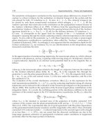
Fig. 2. Model of a ring magnet: amperian equivalence.
that depending on the polarization direction of the source only one of the model generally
yields an analytical formulation. So, the choice rather depends on the considered problem.
2.4 Force calculation
The force transmitted between two axially polarized ring permanent magnets is determined
by using the amperian approach. Thus, each ring is replaced by two coils of N
1
and N
2
turns
in which two currents, I
1
and I
2
, flow. Indeed, a ring magnet whose polarization is axial and
points up, with an inner radius r
1
and an outer one r
2
, can be modelled by a coil of radius
r
2
with a current I
2
flowing anticlockwise and a coil of radius r
1
with a current I
1
flowing
clockwise (Fig.2).
The equivalent surface current densities related to the coil heights h
1
and h
2
are defined as
follows for the calculations:
k
1
= N
1
I
1
/h
1
: equivalent surface current density for the coils of radii r
1
and r
2
.
k
2
= N
2
I
2
/h
2
: equivalent surface current density for the coils of radii r
3
and r
4
.
The axial force, F
z
, created between the two ring magnets is given by:
F
z
=
µ
0
k
1
k
2
2
2
∑
i=1
4
∑
j=3
(−1)
1+i+j
f
z
(r
i
, r
j
)
(2)
with
f
z
(r
i
, r
j
) = r
i
r
j
z
4
z
3
z
2
z
1
2π
0
(
˜
˜
z
−
˜
z
) cos(
˜
θ
)d
˜
zd
˜
˜
zd
˜
θ
r
2
i
+ r
2
j
−2r
i
r
j
cos(
˜
θ
) + (
˜
˜
z
−
˜
z
)
2
3
2
Parameter Definition
β
b+c
b−c
µ
c
b+c
c
c−b
Table 1. Parameters in the analytical expression of the force exerted between two axially po-
larized ring magnets.
The current densities are linked to the magnet polarizations by:
k
1
=
J
1
µ
0
(3)
and
k
2
=
J
2
µ
0
(4)
Then the axial force becomes:
F
z
=
J
1
J
2
2µ
0
2
∑
i,k= 1
4
∑
j,l=3
(−1)
(1+i +j +k+l)
F
i,j,k,l
(5)
with
F
i,j,k,l
= r
i
r
j
g
z
k
−z
l
, r
2
i
+ r
2
j
+ (z
k
−z
l
)
2
, −2r
i
r
j
(6)
g
(a, b, c) = A + S
A
=
a
2
−b
c
π
+
c
2
−(a
2
−b)
2
c
log
−16c
2
(c
2
−(a
2
−b)
2
)
(
3
2
)
+ log
c
2
(c
2
−(a
2
−b)
2
)
(
3
2
)
S
=
2ia
c
√
b + c
(b + c)E
arcsin
β, β
−1
−cF
arcsin
β, β
−1
+
2 a
c
√
b −c
√
c
√
µ
E
β
−1
−c
√
µK
β
−1
+
β
−1
(b − a
2
)K
[
2µ
]
+ (
a
2
−b + c)Π
2c
b + c − a
2
, 2µ
(7)
The special functions used are defined as follows:
K
[
m
]
is the complete elliptic integral of the first kind.
K
[
m
]
=
π
2
0
1
1 −m sin(θ)
2
dθ (8)
Magnetic Bearings, Theory and Applications90
F
[
φ, m
]
is the incomplete elliptic integral of the first kind.
F
[
φ, m
]
=
φ
0
1
1 −m sin(θ)
2
dθ (9)
E
[
φ, m
]
is the incomplete elliptic integral of the second kind.
E
[
φ, m
]
=
φ
0
1 −m sin(θ)
2
dθ (10)
E
[
m
]
=
π
2
0
1 −m sin(θ)
2
dθ (11)
Π
[
n, m
]
is the incomplete elliptic integral of the third kind.
Π
[
n, m
]
=
Π
n,
π
2
, m
(12)
with
Π
[
n, φ, m
]
=
φ
0
1
1 −n sin(θ)
2
1
1 −m sin(θ)
2
dθ (13)
3. Exact analytical formulation of the axial stiffness between two axially polarized
ring magnets.
The axial stiffness, K
z
existing between two axially polarized ring magnets can be calculated
by deriving the axial force transmitted between the two rings, F
z
, with regard to the axial
displacement, z:
K
z
= −
d
dz
F
z
(14)
F
z
is replaced by the integral formulation of Eq.5 and after some mathematical manipulations
the axial stiffness can be written:
K
z
=
J
1
J
2
2µ
0
2
∑
i,k= 1
4
∑
j,l=3
(−1)
(1+i +j +k+l)
C
i,j,k,l
(15)
where
C
i,j,k,l
= 2
√
αE
−4r
i
r
j
α
−2
r
2
i
+ r
2
j
+ (z
k
−z
l
)
2
√
α
K
−4r
i
r
j
α
α
= (r
i
−r
j
)
2
+ (z
k
−z
l
)
2
(16)
4. Study and characteristics of axial bearings with axially polarized ring magnets
and a cylindrical air gap.
4.1 Structures with two ring magnets
This section considers devices constituted of two ring magnets with antiparallel polarization
directions. So, the devices work as axial bearings. The influence of the different parameters
of the geometry on both the axial force and stiffness is studied.
4.1.1 Geometry
The device geometry is shown on Fig.1. The radii remain the same as previously defined. Both
ring magnets have the same axial dimension, the height h
1
= h
2
= h. The axial coordinate,
z, characterizes the axial displacement of the inner ring with regard to the outer one. The
polarization of the magnets is equal to 1T.
The initial set of dimensions for each study is the following:
r
1
= 25mm, r
2
= 28mm, r
3
= 21mm, r
4
= 24mm, h = 3mm
Thus the initial air gap is 1mm wide and the ring magnets have an initial square cross section
of 3
×3mm
2
.
4.1.2 Air gap influence
The ring cross section is kept constant and the radial dimension of the air gap, r
1
−r
3
, is varied
by modifying the radii of the inner ring. Fig.3 and 4 show how the axial force and stiffness are
modified when the axial inner ring position changes for different values of the air gap.
Naturally, when the air gap decreases, the modulus of the axial force for a given axial position
of the inner ring increases (except for large displacements) and so does the modulus of the
axial stiffness. Furthermore, it has to be noted that a positive stiffness corresponds to a stable
configuration in which the force is a pull-back one, whereas a negative stiffness corresponds
to an unstable position: the inner ring gets ejected!
4
2
0
2
4
60
40
20
0
20
40
60
z mm
Axial Force N
Fig. 3. Axial force for several air gap radial dimensions. Blue: r
1
= 25mm, r
2
= 28mm, r
3
=
21mm, r
4
= 24mm, h = 3mm Air gap 1mm, Green: Air gap 0.5mm , Red: Air gap 0.1mm
4.1.3 Ring height influence
The air gap is kept constant as well as the ring radii and the height of the rings is varied.
Fig.5 and 6 show how the axial force and stiffness are modified. When the magnet height
decreases, the modulus of the axial force for a given axial position of the inner ring decreases.
This is normal, as the magnet volume also decreases.
The study of the stiffness is carried out for decreasing ring heights (Fig.6) but also for
increasing ones (Fig.7). As a result, the stiffness doesn’t go on increasing in a significant way
above a given ring height. This means that increasing the magnet height, and consequently
Passive permanent magnet bearings for rotating shaft : Analytical calculation 91
F
[
φ, m
]
is the incomplete elliptic integral of the first kind.
F
[
φ, m
]
=
φ
0
1
1
−m sin(θ)
2
dθ (9)
E
[
φ, m
]
is the incomplete elliptic integral of the second kind.
E
[
φ, m
]
=
φ
0
1
−m sin(θ)
2
dθ (10)
E
[
m
]
=
π
2
0
1
−m sin(θ)
2
dθ (11)
Π
[
n, m
]
is the incomplete elliptic integral of the third kind.
Π
[
n, m
]
=
Π
n,
π
2
, m
(12)
with
Π
[
n, φ, m
]
=
φ
0
1
1
−n sin(θ)
2
1
1
−m sin(θ)
2
dθ (13)
3. Exact analytical formulation of the axial stiffness between two axially polarized
ring magnets.
The axial stiffness, K
z
existing between two axially polarized ring magnets can be calculated
by deriving the axial force transmitted between the two rings, F
z
, with regard to the axial
displacement, z:
K
z
= −
d
dz
F
z
(14)
F
z
is replaced by the integral formulation of Eq.5 and after some mathematical manipulations
the axial stiffness can be written:
K
z
=
J
1
J
2
2µ
0
2
∑
i,k= 1
4
∑
j,l=3
(−1)
(1+i +j +k+l)
C
i,j,k,l
(15)
where
C
i,j,k,l
= 2
√
αE
−4r
i
r
j
α
−2
r
2
i
+ r
2
j
+ (z
k
−z
l
)
2
√
α
K
−4r
i
r
j
α
α
= (r
i
−r
j
)
2
+ (z
k
−z
l
)
2
(16)
4. Study and characteristics of axial bearings with axially polarized ring magnets
and a cylindrical air gap.
4.1 Structures with two ring magnets
This section considers devices constituted of two ring magnets with antiparallel polarization
directions. So, the devices work as axial bearings. The influence of the different parameters
of the geometry on both the axial force and stiffness is studied.
4.1.1 Geometry
The device geometry is shown on Fig.1. The radii remain the same as previously defined. Both
ring magnets have the same axial dimension, the height h
1
= h
2
= h. The axial coordinate,
z, characterizes the axial displacement of the inner ring with regard to the outer one. The
polarization of the magnets is equal to 1T.
The initial set of dimensions for each study is the following:
r
1
= 25mm, r
2
= 28mm, r
3
= 21mm, r
4
= 24mm, h = 3mm
Thus the initial air gap is 1mm wide and the ring magnets have an initial square cross section
of 3
×3mm
2
.
4.1.2 Air gap influence
The ring cross section is kept constant and the radial dimension of the air gap, r
1
−r
3
, is varied
by modifying the radii of the inner ring. Fig.3 and 4 show how the axial force and stiffness are
modified when the axial inner ring position changes for different values of the air gap.
Naturally, when the air gap decreases, the modulus of the axial force for a given axial position
of the inner ring increases (except for large displacements) and so does the modulus of the
axial stiffness. Furthermore, it has to be noted that a positive stiffness corresponds to a stable
configuration in which the force is a pull-back one, whereas a negative stiffness corresponds
to an unstable position: the inner ring gets ejected!
4
2
0
2
4
60
40
20
0
20
40
60
z mm
Axial Force
N
Fig. 3. Axial force for several air gap radial dimensions. Blue: r
1
= 25mm, r
2
= 28mm, r
3
=
21mm, r
4
= 24mm, h = 3mm Air gap 1mm , Green: Air gap 0.5mm , Red: Air gap 0.1mm
4.1.3 Ring height influence
The air gap is kept constant as well as the ring radii and the height of the rings is varied.
Fig.5 and 6 show how the axial force and stiffness are modified. When the magnet height
decreases, the modulus of the axial force for a given axial position of the inner ring decreases.
This is normal, as the magnet volume also decreases.
The study of the stiffness is carried out for decreasing ring heights (Fig.6) but also for
increasing ones (Fig.7). As a result, the stiffness doesn’t go on increasing in a significant way
above a given ring height. This means that increasing the magnet height, and consequently
Magnetic Bearings, Theory and Applications92
4 2 0 2 4
50
0
50
100
z
mm
Axial Stifness
N
mm
Fig. 4. Axial stiffness for several air gap radial dimensions. Blue: r
1
= 25mm, r
2
= 28mm, r
3
=
21mm, r
4
= 24mm, h = 3mm Air gap 1mm , Green: Air gap 0.5mm , Red: Air gap 0.1mm
the magnet volume, above a given value isn’t interesting to increase the stiffness. Moreover,
it has to be noted that when the height is reduced by half, from 3mm to 1.5mm, the stiffness
is only reduced by a third. This points out that in this configuration, the loss on the stiffness
isn’t that bad whereas the gain in volume is really interesting. This result will be useful for
other kinds of bearing structures -stacked structures- in a further section. Besides, the magnet
height shouln’t become smaller than the half of its radial thickness unless the demagnetizing
field inside the magnet becomes too strong and demagnetizes it.
4 2 0 2 4
30
20
10
0
10
20
30
z
mm
Axial Force
N
Fig. 5. Axial force for ring small heights. Blue: r
1
= 25mm, r
2
= 28mm, r
3
= 21mm, r
4
= 24mm,
air gap 1mm h
= 3mm, Green: h = 2mm , Red: h = 1.5mm.
4.1.4 Ring radial thickness influence
Now, the radial thickness of the ring magnets is varied. The ring height, h = 3mm, and the air
gap length, 1mm, are kept constant and the outer radius of the outer ring, r
2
, is increased of
4
2
0
2
4
10
0
10
20
30
z mm
Axial Stifness Nmm
Fig. 6. Axial stiffness for ring small heights. Blue: r
1
= 25mm, r
2
= 28mm, r
3
= 21mm, r
4
=
24mm, air gap 1mm h = 3mm, Green: h = 2mm , Red: h = 1.5mm.
4
2
0
2
4
10
0
10
20
30
z mm
Axial Stifness Nmm
Fig. 7. Axial stiffness for ring large heights. Blue: r
1
= 25mm, r
2
= 28mm, r
3
= 21mm, r
4
=
24mm, air gap 1mm h = 3mm, Green: h = 6mm , Red: h = 9mm.
the same quantity as the inner radius of the inner ring, r
3
, is decreased. So, the inner ring has
always the same radial thickness as the outer one.
When the radial thickness increases, the modulus of the axial force for a given axial dis-
placement of the inner ring also increases (Fig.8). This behavior is expected as once again
the magnet volume increases. However, the ring thickness doesn’t seem a very sensitive
parameter. Indeed, the variation isn’t as dramatic as with the previous studied parameters.
4.1.5 Ring mean perimeter influence
The outer ring perimeter is varied and all the radii are varied to keep the ring cross section
and the air gap constant. As a result, when the device perimeter -or the air gap perimeter-
increases, the modulus of the axial force for a given axial displacement of the inner ring also
Passive permanent magnet bearings for rotating shaft : Analytical calculation 93
4
2
0
2
4
50
0
50
100
z mm
Axial Stifness Nmm
Fig. 4. Axial stiffness for several air gap radial dimensions. Blue: r
1
= 25mm, r
2
= 28mm, r
3
=
21mm, r
4
= 24mm, h = 3mm Air gap 1mm, Green: Air gap 0.5mm , Red: Air gap 0.1mm
the magnet volume, above a given value isn’t interesting to increase the stiffness. Moreover,
it has to be noted that when the height is reduced by half, from 3mm to 1.5mm, the stiffness
is only reduced by a third. This points out that in this configuration, the loss on the stiffness
isn’t that bad whereas the gain in volume is really interesting. This result will be useful for
other kinds of bearing structures -stacked structures- in a further section. Besides, the magnet
height shouln’t become smaller than the half of its radial thickness unless the demagnetizing
field inside the magnet becomes too strong and demagnetizes it.
4
2
0
2
4
30
20
10
0
10
20
30
z mm
Axial Force N
Fig. 5. Axial force for ring small heights. Blue: r
1
= 25mm, r
2
= 28mm, r
3
= 21mm, r
4
= 24mm,
air gap 1mm h
= 3mm, Green: h = 2mm , Red: h = 1.5mm.
4.1.4 Ring radial thickness influence
Now, the radial thickness of the ring magnets is varied. The ring height, h = 3mm, and the air
gap length, 1mm, are kept constant and the outer radius of the outer ring, r
2
, is increased of
4 2 0 2 4
10
0
10
20
30
z
mm
Axial Stifness
N
mm
Fig. 6. Axial stiffness for ring small heights. Blue: r
1
= 25mm, r
2
= 28mm, r
3
= 21mm, r
4
=
24mm, air gap 1mm h = 3mm, Green: h = 2mm , Red: h = 1.5mm.
4
2
0
2
4
10
0
10
20
30
z
mm
Axial Stifness
N
mm
Fig. 7. Axial stiffness for ring large heights. Blue: r
1
= 25mm, r
2
= 28mm, r
3
= 21mm, r
4
=
24mm, air gap 1mm h = 3mm, Green: h = 6mm , Red: h = 9mm.
the same quantity as the inner radius of the inner ring, r
3
, is decreased. So, the inner ring has
always the same radial thickness as the outer one.
When the radial thickness increases, the modulus of the axial force for a given axial dis-
placement of the inner ring also increases (Fig.8). This behavior is expected as once again
the magnet volume increases. However, the ring thickness doesn’t seem a very sensitive
parameter. Indeed, the variation isn’t as dramatic as with the previous studied parameters.
4.1.5 Ring mean perimeter influence
The outer ring perimeter is varied and all the radii are varied to keep the ring cross section
and the air gap constant. As a result, when the device perimeter -or the air gap perimeter-
increases, the modulus of the axial force for a given axial displacement of the inner ring also
Magnetic Bearings, Theory and Applications94
4 2 0 2 4
40
20
0
20
40
z
mm
Axial Force
N
Fig. 8. Axial force for several radial thicknesses. Blue: r
1
= 25mm, r
2
= 28m m, r
3
=
21mm, r
4
= 24mm, h = 3mm, air gap 1mm, Radial thickness r
2
−r
1
= r
4
−r
3
= 3mm, Green:
4mm , Red: 5mm.
increases (Fig.9). This result is expected as the magnet volume also increases.
4 2 0 2 4
60
40
20
0
20
40
60
z
mm
Axial Force
N
Fig. 9. Axial force for several air gap perimeters. h = 3mm, air gap 1mm. Blue: r
1
=
25mm, r
2
= 28m m, r
3
= 21mm, r
4
= 24m m. Green: r
1
= 37mm, r
2
= 40mm, r
3
= 33m m, r
4
=
36mm. Red: r
1
= 50mm, r
2
= 53mm, r
3
= 46mm, r
4
= 49mm.
4.1.6 Maximum axial force
Previous results are interesting as they show the shape of the axial force and stiffness when
different dimensional parameters are varied. Nevertheless, it is necessary to complete these
results with additional studies, such as the study of the maximum force for example, in or-
der to compare them. Indeed, a general conclusion is that the axial force increases when the
magnet volume increases, but the way it increases depends on the parameter which makes
the volume increase.
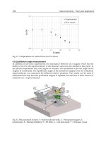
So, the blue line on Fig.10 shows that the maximum force varies linearly with the air gap
diameter. Furthermore, this variation is also linear for radially thicker ring magnets (green
and red lines on Fig.10).
As a conclusion, the maximum axial force, and the axial stiffness too, is proportional to the air
gap diameter, as long as this diameter isn’t too small (which means above 5mm).
20
40
60
80
100
0
50
100
150
Diameter mm
Maximum Axial Force N
Fig. 10. Maximum axial force versus the air gap perimeter for several ring radial thicknesses.
Air gap 1mm, h
= 3mm. Blue: r
1
= 25mm, r
2
= 28mm, r
3
= 21mm, r
4
= 24mm Radial
thickness r
2
−r
1
= r
4
−r
3
= 3mm, Green: Radial thickness 4mm , Red: Radial thickness 5mm.
Moreover, the blue line on Fig.11 shows that the maximum force varies inversely to the square
of the air gap radial dimension. Thus, the maximum axial force is very sensitive to the air
gap radial dimension, which should be as small as possible to have large forces but which is
generally set by the mechanical constraints of the device. As a remark, for ring magnets of
3
×3mm
2
cross section, if the radial mechanical air gap has to be 2mm, the axial force exerted
is rather negligible!
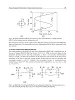
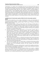
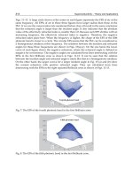
4.2 Multiple ring structures: stacked structures
A remark of the previous section will be exploited now. Indeed, the study of the ring height
shew that diminishing the magnet height, and thus its volume, could be done without a dra-
matical decrease of the force. Hence the idea of using rather short rings but of stacking them
with alternate polarization directions to achieve larger forces.
For example, let’s consider a stack of elementary devices of same dimensions as the previously
considered devices: r
1
= 25mm, r
2
= 28mm, r
3
= 21mm, r
4
= 24mm, h = 3mm, cross section
3
×3mm
2
. The bottom of the first device is located at z = 0, the bottom of the second one at
z
= 3 and so on (Fig. 12).
Fig.13 shows the axial stiffness for the elementary device (blue), for a stack of two elementary
devices (green) and for a stack of three elementary devices (red). The consequence of stacking
is that the different axial stiffnesses are additive, as they all act in the same way. So, the total
axial stiffness of the device increases more rapidly than the number of stacked devices (Yonnet
et al., 1991). Indeed, the maximal stiffness for one ring pair with a square section of 3
×3mm
2
is 30.8 N/mm, for two pairs 87.9 N/mm and for three pairs 140 N/mm. If n is the number of
pairs, the stiffness of a stack is approximately 2n
−1 times greater than the stiffness of a pair.
Passive permanent magnet bearings for rotating shaft : Analytical calculation 95
4
2
0
2
4
40
20
0
20
40
z mm
Axial Force N
Fig. 8. Axial force for several radial thicknesses. Blue: r
1
= 25mm, r
2
= 28m m, r
3
=
21mm, r
4
= 24mm, h = 3mm, air gap 1mm, Radial thickness r
2
−r
1
= r
4
−r
3
= 3mm, Green:
4mm , Red: 5mm.
increases (Fig.9). This result is expected as the magnet volume also increases.
4
2
0
2
4
60
40
20
0
20
40
60
z mm
Axial Force N
Fig. 9. Axial force for several air gap perimeters. h = 3mm, air gap 1mm. Blue: r
1
=
25mm, r
2
= 28m m, r
3
= 21mm, r
4
= 24m m. Green: r
1
= 37mm, r
2
= 40mm, r
3
= 33m m, r
4
=
36mm. Red: r
1
= 50mm, r
2
= 53mm, r
3
= 46mm, r
4
= 49mm.
4.1.6 Maximum axial force
Previous results are interesting as they show the shape of the axial force and stiffness when
different dimensional parameters are varied. Nevertheless, it is necessary to complete these
results with additional studies, such as the study of the maximum force for example, in or-
der to compare them. Indeed, a general conclusion is that the axial force increases when the
magnet volume increases, but the way it increases depends on the parameter which makes
the volume increase.
So, the blue line on Fig.10 shows that the maximum force varies linearly with the air gap
diameter. Furthermore, this variation is also linear for radially thicker ring magnets (green
and red lines on Fig.10).
As a conclusion, the maximum axial force, and the axial stiffness too, is proportional to the air
gap diameter, as long as this diameter isn’t too small (which means above 5mm).
20 40 60 80 100
0
50
100
150
Diameter
mm
Maximum Axial Force
N
Fig. 10. Maximum axial force versus the air gap perimeter for several ring radial thicknesses.
Air gap 1mm, h
= 3mm. Blue: r
1
= 25mm, r
2
= 28mm, r
3
= 21mm, r
4
= 24mm Radial
thickness r
2
−r
1
= r
4
−r
3
= 3mm, Green: Radial thickness 4mm , Red: Radial thickness 5mm.
Moreover, the blue line on Fig.11 shows that the maximum force varies inversely to the square
of the air gap radial dimension. Thus, the maximum axial force is very sensitive to the air
gap radial dimension, which should be as small as possible to have large forces but which is
generally set by the mechanical constraints of the device. As a remark, for ring magnets of
3
×3mm
2
cross section, if the radial mechanical air gap has to be 2mm, the axial force exerted
is rather negligible!
4.2 Multiple ring structures: stacked structures
A remark of the previous section will be exploited now. Indeed, the study of the ring height
shew that diminishing the magnet height, and thus its volume, could be done without a dra-
matical decrease of the force. Hence the idea of using rather short rings but of stacking them
with alternate polarization directions to achieve larger forces.
For example, let’s consider a stack of elementary devices of same dimensions as the previously
considered devices: r
1
= 25mm, r
2
= 28mm, r
3
= 21mm, r
4
= 24mm, h = 3mm, cross section
3
×3mm
2
. The bottom of the first device is located at z = 0, the bottom of the second one at
z
= 3 and so on (Fig. 12).
Fig.13 shows the axial stiffness for the elementary device (blue), for a stack of two elementary
devices (green) and for a stack of three elementary devices (red). The consequence of stacking
is that the different axial stiffnesses are additive, as they all act in the same way. So, the total
axial stiffness of the device increases more rapidly than the number of stacked devices (Yonnet
et al., 1991). Indeed, the maximal stiffness for one ring pair with a square section of 3
×3mm
2
is 30.8 N/mm, for two pairs 87.9 N/mm and for three pairs 140 N/mm. If n is the number of
pairs, the stiffness of a stack is approximately 2n
−1 times greater than the stiffness of a pair.
Magnetic Bearings, Theory and Applications96
0.5
1.0
1.5
2.0
20
30
40
50
60
70
80
Airgap mm
Maximum Axial Force
N
Fig. 11. Maximum axial force versus the air gap radial dimension for several ring radial thick-
nesses. h
= 3mm. Blue: r
1
= 25mm, r
2
= 28mm, r
3
= 21mm, r
4
= 24mm Radial thickness
r
2
−r
1
= r
4
−r
3
= 3mm, Green: Radial thickness 4mm , Red: Radial thickness 5mm.
Fig. 12. Cross-section of a stack of three elementary devices with alternate axial polarizations.
Besides, the stiffness obtained for a ring pair of same total dimensions as the stack of three
pairs is 34.7 N/mm. This example emphazises the advantage, for a given volume and a suf-
ficient axial height, of splitting the ring into several rings of smaller heights and opposite
polarizations: making three pairs increases the stiffness fourfold. The splitting is interesting
as long as the height of each ring magnet is large enough (see section 4.1.3).
5. Study and characteristics of axial bearings with axially polarized ring magnets
and a plane air gap.
This section considers devices with two axially polarized ring magnets of exactly the
same dimensions. They are positioned so as to have the same rotation axis and thus are
separated by a plane air gap. In this configuration, if the rings have the same polarization
direction, the device works as a radial bearing, if the polarizations are opposite, it works
as an axial bearing. It is noticeable that for axial polarizations, parallel polarizations yield
4
2
0
2
4
100
50
0
50
100
z mm
Axial Stifness Nmm
Fig. 13. Axial stiffness for one elementary device (blue), for a stack of two elementary devices
(green) and three elementary devices (red).
radial bearings whereas antiparallel polarizations yield axial ones, whatever the air gap shape.
For these structures, the axial displacement of one ring corresponds to an air gap variation.
Of course, the maximal axial force between the rings occurs when they are axially in contact
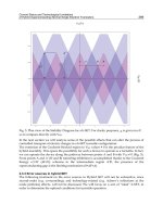
with each other. When the air gap, z, increases, the axial force decreases, as show on Fig.15.
As the variation is monotonous, the axial stiffness has always the same sign (Fig. 16) and the
force the same nature (restoring, here).
0
z
Fig. 14. Cross-section of a bearing with a plane air gap
Moreover, the axial force depends on the size of surfaces which are facing each other. There-
fore, it is obvious that when the ring radial thickness increases, the force increases in the same
way. The only other interesting parameter is the ring axial height. Figure 17 and 18 show how
the axial force and stiffness vary when the air gap changes for different ring axial height. The
force doesn’t seem to vary greatly when the magnet height changes, and the stiffness even
less. But the attention should be drawn to the scale of the force amplitude. Indeed, Fig.19
and 20 show the force and the stiffness for a fixed air gap when the magnet height varies.
Passive permanent magnet bearings for rotating shaft : Analytical calculation 97
0.5
1.0
1.5
2.0
20
30
40
50
60
70
80
Airgap mm
Maximum Axial Force N
Fig. 11. Maximum axial force versus the air gap radial dimension for several ring radial thick-
nesses. h
= 3mm. Blue: r
1
= 25mm, r
2
= 28mm, r
3
= 21mm, r
4
= 24mm Radial thickness
r
2
−r
1
= r
4
−r
3
= 3mm, Green: Radial thickness 4mm , Red: Radial thickness 5mm.
Fig. 12. Cross-section of a stack of three elementary devices with alternate axial polarizations.
Besides, the stiffness obtained for a ring pair of same total dimensions as the stack of three
pairs is 34.7 N/mm. This example emphazises the advantage, for a given volume and a suf-
ficient axial height, of splitting the ring into several rings of smaller heights and opposite
polarizations: making three pairs increases the stiffness fourfold. The splitting is interesting
as long as the height of each ring magnet is large enough (see section 4.1.3).
5. Study and characteristics of axial bearings with axially polarized ring magnets
and a plane air gap.
This section considers devices with two axially polarized ring magnets of exactly the
same dimensions. They are positioned so as to have the same rotation axis and thus are
separated by a plane air gap. In this configuration, if the rings have the same polarization
direction, the device works as a radial bearing, if the polarizations are opposite, it works
as an axial bearing. It is noticeable that for axial polarizations, parallel polarizations yield
4
2
0
2
4
100
50
0
50
100
z
mm
Axial Stifness
N
mm
Fig. 13. Axial stiffness for one elementary device (blue), for a stack of two elementary devices
(green) and three elementary devices (red).
radial bearings whereas antiparallel polarizations yield axial ones, whatever the air gap shape.
For these structures, the axial displacement of one ring corresponds to an air gap variation.
Of course, the maximal axial force between the rings occurs when they are axially in contact
with each other. When the air gap, z, increases, the axial force decreases, as show on Fig.15.
As the variation is monotonous, the axial stiffness has always the same sign (Fig. 16) and the
force the same nature (restoring, here).
0
z
Fig. 14. Cross-section of a bearing with a plane air gap
Moreover, the axial force depends on the size of surfaces which are facing each other. There-
fore, it is obvious that when the ring radial thickness increases, the force increases in the same
way. The only other interesting parameter is the ring axial height. Figure 17 and 18 show how
the axial force and stiffness vary when the air gap changes for different ring axial height. The
force doesn’t seem to vary greatly when the magnet height changes, and the stiffness even
less. But the attention should be drawn to the scale of the force amplitude. Indeed, Fig.19
and 20 show the force and the stiffness for a fixed air gap when the magnet height varies.
Magnetic Bearings, Theory and Applications98
0.5 1.0 1.5 2.0 2.5 3.0
0
20
40
60
80
100
120
z
mm
Axial Force
N
Fig. 15. Axial force when the plane air gap length, z, varies. r
1
= r
3
= 25mm, r
2
= r
4
=
28mm, h = 3mm.
0.5 1.0 1.5 2.0 2.5 3.0
0
20
40
60
80
100
120
z mm
Axial Stifness
N
mm
Fig. 16. Axial stiffness when the plane air gap length, z, varies. r
1
= r
3
= 25mm, r
2
= r
4
=
28mm, h = 3mm.
They emphazise the fact that increasing the magnet height is interesting for small heights, but
becomes rapidly inefficient, especially with regard to the stiffness.
6. Determination of the force transmitted between two radially polarized ring per-
manent magnets.
The structure considered now is shown in Fig 21. The device is constituted by two concentric
ring magnets which are separated by a cylindrical air gap and are radially polarized, their
polarizations being in the same direction.
6.1 Notations
The parameters which describe the geometry of Fig.21 and its properties are listed below:
J
1
: outer ring polarization [T].
J
2
: inner ring polarization [T].
0.5
1.0
1.5
2.0
2.5
3.0
0
20
40
60
80
100
120
140
z mm
Axial Force N
Fig. 17. Axial force when the plane air gap length, z, varies. r
1
= r
3
= 25mm, r
2
= r
4
= 28mm.
Blue: h
= 3mm, Green: h = 2mm , Red: h = 4mm.
r
in
, r
out
: radial coordinates of the outer ring [m].
r
in2
, r
out2
: radial coordinates of the inner ring [m].
h: outer ring height [m].
z
b
−z
a
: inner ring height [m].
The rings are radially centered and their polarizations are supposed to be uniformly radial.
6.2 Magnet modelling
For this kind of configuration, the coulombian model of magnets is the one that gives interest-
ing analytical and semi analytical expressions. Consequently, each ring permanent magnet is
represented by two curved planes which correspond to the inner and outer faces of the rings.
These faces are charged with a surface magnetic pole density σ
∗
and the charge balance is
reached thanks to a magnetic pole volume density σ
∗
v
. For each ring, the inner face is charged
with the surface magnetic pole density
+σ
∗
and the outer one is charged with the surface
magnetic pole density
−σ
∗
. Moreover, all the calculations are carried out with σ
∗
=
J.
n = 1T
where
J is the magnetic polarization vector and
n is the unit normal vector which is directed
towards the rotation axis.
6.3 Expression of the force
The axial force exerted between the magnets results of the interaction of all the charge densi-
ties. The axial component of the magnetic field produced by the outer ring permanent magnet
is H
z
. Thus, the axial force F
z
can be written as follows:
F
z
=
(S
in
)
H
z
σ
∗
2
d
˜
S −
(S
out
)
H
z
σ
∗
2
d
˜
S +
(V)
H
z
σ
∗
2
r
2
d
˜
V (17)
where σ
∗
2
is the magnetic pole surface density of the inner ring magnet, ( S
in
) is the surface of
the inner face of the inner ring permanent magnet,
(S
out
) is the surface of the outer face of the
inner ring permanent magnet and
(V) is the volume of the inner ring permanent magnet. So,
Passive permanent magnet bearings for rotating shaft : Analytical calculation 99
0.5
1.0
1.5
2.0
2.5
3.0
0
20
40
60
80
100
120
z mm
Axial Force N
Fig. 15. Axial force when the plane air gap length, z, varies. r
1
= r
3
= 25mm, r
2
= r
4
=
28mm, h = 3mm.
0.5
1.0
1.5
2.0
2.5
3.0
0
20
40
60
80
100
120
z mm
Axial Stifness Nmm
Fig. 16. Axial stiffness when the plane air gap length, z, varies. r
1
= r
3
= 25mm, r
2
= r
4
=
28mm, h = 3mm.
They emphazise the fact that increasing the magnet height is interesting for small heights, but
becomes rapidly inefficient, especially with regard to the stiffness.
6. Determination of the force transmitted between two radially polarized ring per-
manent magnets.
The structure considered now is shown in Fig 21. The device is constituted by two concentric
ring magnets which are separated by a cylindrical air gap and are radially polarized, their
polarizations being in the same direction.
6.1 Notations
The parameters which describe the geometry of Fig.21 and its properties are listed below:
J
1
: outer ring polarization [T].
J
2
: inner ring polarization [T].
0.5 1.0 1.5 2.0 2.5 3.0
0
20
40
60
80
100
120
140
z
mm
Axial Force
N
Fig. 17. Axial force when the plane air gap length, z, varies. r
1
= r
3
= 25mm, r
2
= r
4
= 28mm.
Blue: h
= 3mm, Green: h = 2mm , Red: h = 4mm.
r
in
, r
out
: radial coordinates of the outer ring [m].
r
in2
, r
out2
: radial coordinates of the inner ring [m].
h: outer ring height [m].
z
b
−z
a
: inner ring height [m].
The rings are radially centered and their polarizations are supposed to be uniformly radial.
6.2 Magnet modelling
For this kind of configuration, the coulombian model of magnets is the one that gives interest-
ing analytical and semi analytical expressions. Consequently, each ring permanent magnet is
represented by two curved planes which correspond to the inner and outer faces of the rings.
These faces are charged with a surface magnetic pole density σ
∗
and the charge balance is
reached thanks to a magnetic pole volume density σ
∗
v
. For each ring, the inner face is charged
with the surface magnetic pole density
+σ
∗
and the outer one is charged with the surface
magnetic pole density
−σ
∗
. Moreover, all the calculations are carried out with σ
∗
=
J.
n = 1T
where
J is the magnetic polarization vector and
n is the unit normal vector which is directed
towards the rotation axis.
6.3 Expression of the force
The axial force exerted between the magnets results of the interaction of all the charge densi-
ties. The axial component of the magnetic field produced by the outer ring permanent magnet
is H
z
. Thus, the axial force F
z
can be written as follows:
F
z
=
(S
in
)
H
z
σ
∗
2
d
˜
S −
(S
out
)
H
z
σ
∗
2
d
˜
S +
(V)
H
z
σ
∗
2
r
2
d
˜
V (17)
where σ
∗
2
is the magnetic pole surface density of the inner ring magnet, ( S
in
) is the surface of
the inner face of the inner ring permanent magnet,
(S
out
) is the surface of the outer face of the
inner ring permanent magnet and
(V) is the volume of the inner ring permanent magnet. So,
Magnetic Bearings, Theory and Applications100
0.5 1.0 1.5 2.0 2.5 3.0
0
20
40
60
80
100
120
140
z
mm
Axial Stifness
N
mm
Fig. 18. Axial stiffness when the plane air gap length, z, varies. r
1
= r
3
= 25mm,r
2
= r
4
=
28mm. Blue: h = 3mm, Green: h = 2mm , Red: h = 4mm.
the axial force F
z
can be expressed by:
F
z
= −
2π
θ
1
=0
h
z
1
=0
2π
θ
2
=0
z
b
z
2
=z
a
a(r
in
, r
out2
)dz
1
dθ
1
dz
2
dθ
2
+
2π
θ
1
=0
h
z
1
=0
2π
θ
2
=0
z
b
z
2
=z
a
a(r
out
, r
out2
)dz
1
dθ
1
dz
2
dθ
2
+
2π
θ
1
=0
h
z
1
=0
2π
θ
2
=0
z
b
z
2
=z
a
a(r
in
, r
in2
)dz
1
dθ
1
dz
2
dθ
2
−
2π
θ
1
=0
h
z
1
=0
2π
θ
2
=0
z
b
z
2
=z
a
a(r
out
, r
in2
)dz
1
dθ
1
dz
2
dθ
2
−
r
out
r
1
=r
in
2π
θ
1
=0
h
z
1
=0
2π
θ
2
=0
z
b
z
2
=z
a
b(r
out2
, r
1
)dr
1
dz
1
dθ
1
dz
2
dθ
2
+
r
out
r
1
=r
in
2π
θ
1
=0
h
z
1
=0
2π
θ
2
=0
z
b
z
2
=z
a
b(r
in2
, r
1
)dr
1
dz
1
dθ
1
dz
2
dθ
2
+
r
out2
r
2
=r
in2
2π
θ
1
=0
h
z
1
=0
2π
θ
2
=0
z
b
z
2
=z
a
b(r
in
, r
2
)dz
1
dθ
1
dr
2
dz
2
dθ
2
−
r
out2
r
2
=r
in2
2π
θ
1
=0
h
z
1
=0
2π
θ
2
=0
z
b
z
2
=z
a
b(r
out
, r
2
)dz
1
dθ
1
dr
2
dz
2
dθ
2
+
r
out
r
1
=r
in
r
out2
r
2
=r
in2
2π
θ
1
=0
h
z
1
=0
2π
θ
2
=0
z
b
z
2
=z
a
c(r
1
, r
2
)dr
1
dz
1
dθ
1
dr
2
dz
2
dθ
2
(18)
with
a
(α, β) =
σ
∗
1
σ
∗
2
4πµ
0
(z
2
−z
1
)αβ
(
α
2
+ β
2
−2αβ + (z
2
−z
1
)
2
)
3
2
(19)
1
2
3
4
5
6
0
20
40
60
80
h mm
Axial Force N
Fig. 19. Axial force when the ring axial height, h, varies. Plane air gap z = 1mm, r
1
= r
3
=
25mm, r
2
= r
4
= 28mm.
where σ
∗
1
is the magnetic pole surface density of the outer ring magnet. and
b
(α, β) =
a(α, β)
β
(20)
c
(α, β) =
a(α, β)
αβ
(21)
The next step is to evaluate Eq.
(18). Therefore, the number of integrals is first reduced by
integrating analytically a
(α, β), b(α, β) and c(α, β) according to the integral variables. Un-
fortunately, a fully analytical expression of the force can’t be found but the following semi-
analytical expression is quite useful:
F
z
=
σ
∗
1
σ
∗
2
2µ
0
2π
θ
1
=0
Sdθ
1
+
σ
∗
1
σ
∗
2
2µ
0
2π
θ
1
=0
Mdθ
1
+
σ
∗
1
σ
∗
2
2µ
0
2π
θ
1
=0
r
out2
r
2
=r
in2
Vdθ
1
dr
2
(22)
where S represents the interaction between the magnetic pole surface densities of each ring
magnet, M corresponds to the magnetic interaction between the magnetic pole surface densi-
ties of one ring permanent magnet and the magnetic pole volume density of the other one, and
V denotes the interaction between the magnetic pole volume densities of each ring permanent
magnet.