Báo cáo hóa học: " Measurement of local two-phase flow parameters of nanofluids using conductivity double-sensor probe" pot
Bạn đang xem bản rút gọn của tài liệu. Xem và tải ngay bản đầy đủ của tài liệu tại đây (524.66 KB, 8 trang )
NANO EXPRESS Open Access
Measurement of local two-phase flow parameters
of nanofluids using conductivity double-sensor
probe
Yu sun Park
*
and Soon Heung Chang
Abstract
A two-phase flow experiment using air and water-based g-Al
2
O
3
nanofluid was conducted to observe the basic
hydraulic phenomenon of nanofluids. The local two-phase flow parameters were measured with a conductivity
double-sensor two-phase void meter. The void fraction, interfacial velocity, interfacial area concentration, and mean
bubble diameter were evaluated, and all of those results using the nanofluid were compared with the
corresponding results for pure water. The void fraction distribution was flattened in the nanofluid case more than
it was in the pure water case. The higher interfacial area concentration resulted in a smaller mean bubble diameter
in the case of the nanofluid. This was the first attempt to measure the local two-phase flow parameters of
nanofluids using a conductivity double-sensor two-phase void meter. Throughout this experimental study, the
differences in the internal two-phase flo w structure of the nanofluid were identified. In addition, the heat transfer
enhancement of the nanofluid can be resulted from the increase of the interfacial area concentration which means
the available area of the heat and mass transfer.
Introduction
The conventional method of increasing the cooling rate
is to use extended heat transfer surfaces for exchanging
heat with a heat transfer fluid. However, because this
approach requires an undesirable increase in the size of
the syst em, there is a need to develop advanced cooling
techniques and innovat ive heat transfer performan ces
than those presently available. Over the last several dec-
ades, engineers have attempted to develop fluids which
offer better cooling performances for a variety of ther-
mal systems compared to conventional heat transfer
fluids. This motivation inspired Choi [1] to pioneer the
development of nanofluids. A nanofluid is a new type of
fluid that consists o f uniformly dispersed and suspended
nanometer-sized particles or fibers in fluids with unpre-
cedented thermal characteristics.
Numerous research groups from around the world
have published a large number of experimental and the-
oretical studies on nanofluids. A certain group argued
that nanofluids substantiall yenhancetheheattransfer
rate compared to the pure water, while the others found
that the inclusion of nanoparticles degraded the boiling
performance with increasing the particle concentration.
Despite these conflicting research results, the impact of
nanofluid technology i s expected to be great considering
that the heat transfer performance of heat exchangers is
vital in numerous industries. In addition, due to the
small size of nanoparticles and low volume fraction,
problems such as sedimentation, clogging, and abrasion
become insignificant with the reduction in required
pumping power.
While a considerable body of research exists regarding
the heat transfer characteristics of nanofluids, the basic
hydraulic phenomenon of a nanofluid, especially in the
two-phase flow region, has not been investigated as
much. Moreover, there was no attempt t o identify the
internal structure of the two-phase flow of nanofluids.
Hence, in this study, a two-ph ase flow experiment using
an air-nanofluid was conducted. To observe the basic
hydraulic phenomenon of nanofluids, the local t wo-
phase flow parameters such as void fraction distribution
and interfacial area concentration were measured using
aconductivitydouble-sensortwo-phasevoidmeterina
vertically upward air-wa ter two-phase f low. The results
* Correspondence:
Department of Nuclear and Quantum Engineering, KAIST, 335 Gwahak-ro,
Yuseong-gu, Daejeon 305-701, Republic of Korea
Park and Chang Nanoscale Research Letters 2011, 6:284
/>© 2011 Park and Chang; licensee Springer. This is an Open Access article distributed under the terms of the Creative Commons
Attribution License (htt p://creativecommons.org/licenses/by/2.0), which permits unrestricted use, distribution, an d reproduction in
any medium, provided the original work is properly cited.
obtained from the nanofluids were compared with the
results obtained from pure water.
Experimental apparatus
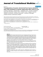
The overall test loop setup is shown in Figure 1. The
setup consists of a tank in which the working fluid is
stored, a pump circulating the working fluid at a vari-
able speed, and the test section. There are six K-type
thermocouples that measure the bulk temperatures of
the w orking fluid. Measured temperatures were used to
determine the fluid properties which were required to
evaluate the experimental results. The measurement
uncertainty of the thermocouples was estimated to be
2.2°C. The volume flow rate of the liquid is measured
with a TOSHIBA LF400 flow meter (TOSHIBA Cor-
poration, Tokyo, Japan) at an uncertainty level of about
0.1%. The air flow rate is controlled by an air Viton
O-ri ng mass flow controller, (model M3030V; manufac-
tured by Line Tech 400, Daejeon, Korea). The measure-
ment error rate of the air flow meter is estimated to be
less than 1%. The total volume of the test loop is about
288 L, and only 60 L of the working fluid is circulated
in the test loop. The working fluids ar e water, air, and a
water-based nanofluid; they are all used under
atmospheric pressure.
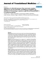
Test section is a vertically oriented acrylic tube as
shown in Figure 2. The inner diameter of t he test sec-
tion is 0.015 m and the total height is 2.5 m to ensure
that the L/D exceeds 100. Nanofluid and air are mixed
at the bottom of the test section and driven by a pump
to flow upward. For the bubble formation in the flow, a
bubble formation bed is installed on the right before the
test section inlet. There are 61 small holes each with a
diameter of 1 mm, and they are spaced 2 mm f rom
each other on the bubble formation bed.
In this experiment, a double-sensor two-pha se void
meter was used as the phase identifier for the two-p hase
mixture. The conductivity double-sensor two-phase void
meter was first proposed by N eal and Bankoff [2]. The
double-sensor electrodes consist of two exposed tips, a
front sensor and a rear sensor, besides an electrically
insulated metal wire and work independently. By consid-
ering the fundamental difference in the conductivity
between water and air, the circuit is closed when the
sensor is in the liquid and is opened when the sensor is
in contact with air. The voltage drop across the sensor
fluctuates between two reference voltages when the cir-
cuit is opened and closed. The information recorded
from each signal includes the number of bubbles that
strike the sensor, the time that the sensor is exposed to
the gas phase, the relative t ime between the bubble
striking the front and rear sensor, and the total sampling
time. This information is used to calculate the local
two-phase flow parameters: namely, the void fraction,
the bubble diameter, the interfacial velocity, and the
interfacial area concentration.
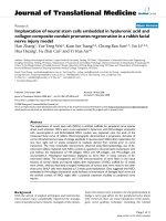
The conductivity double-sensor two-phase void meter
is mounted at a height of 1.75 m from the bottom of
thetestsectionasshownintheFigure3.Theposition
of the L-shape sensor tip in the radial direction is con-
trolled by a micrometer attached onto the sensor. The
output voltage of two-phase identification signal is
obtained for 2 s at a 50-kHz sampling freque ncy. Three
times of measurement were conducted at a total of 15
points from the center to the tube inner wall, and the
averaged value at each point was used for the analysis.
In this study, the same type of a conductivity double-
sensor two-phase void meter which was used by Walter
[3] was installed and the measurement uncertainty of
the void meter is estimated to have a maximum value of
10.5%.
In this study, the bubbly flow regime and the slug flow
regime were investigated. The flow regime map pro-
posed by Mishima and Ishii [4] was used to identify
Figure 1 An overview of the experimental test loop.
Park and Chang Nanoscale Research Letters 2011, 6:284
/>Page 2 of 8
each flow regime. As shown in Table 1, a total of 13
flow conditions for the bubbly and slug flow regimes
were selected with proper superficial velocities.
For the synthesis of nanofluid, g-Al
2
O
3
nanoparticle
powder manufactured by Nanostructured & Amorphous
Materials Inc. (Houston, TX, USA) was used. The aver-
ageparticlesizeofthepowderwas25nmat99.97%
purity based on the information provided by the manu-
facturer. After the mixing of the g -Al
2
O
3
powder with
distilled water, it was placed in an ultrasonic bath for an
hour for particle dispersion. The nanofluid was then
placed in a room temperature atmosphere for 24 h to
form an electrical double layer, which makes the nano-
fluid more stable. This synthesized nan ofluid was placed
in the ultrasonic bath again for 1 h immediately before
the experiment. For a stability check, the zeta potentials
were measured before and after the experiments for sev-
eral concentrations of the g-Al
2
O
3
nanofluid. The aver-
age values are shown in Table 2; the most stable case of
0.1% was the target concentration for the analysis and
discussion.
Data reduction
Fluid properties
The physical properties of the density and viscosity of
the nanofluid were calculated using the published corre-
lations shown below. The density of the nanofluid was
calculated with the following equation from Pak and
Cho [5]:
ρ
nf
= ϕρ
p
+(1− ϕ)ρ
p
w
(1)
The viscosity of the nanofluid was obtained from
Equation 2 which was suggested by Drew and Passman
[6].
μ
nf
=(1+2.5ϕ)μ
pw
(2)
Equation 2 can be applied to volume fractions of less
than 5.0 vol.%. In the present study, the volume concen-
tration of nanopartic le used was 0.1%; thus, this equa-
tion can be applied to estimate the viscosity of the
nanofluid [7].
Void fraction
In general, the area-averaged gas fraction is referred to
as the void fraction. If the cross-sectional area of the
channel is A and the cross-sectional areas oc cupied by
the gas and liquid phases are A
g
and A
f
, respectively,
then the void fraction is given by
α
=
A
g
A
,(1− α)=
A
f
A
(3)
In this experiment, the time-averaged void fraction, a,
is evaluated as a function of the total sampling time, Ω,
Figure 2 Specified design of the test section.
Figure 3 Mounting the conductivity double-sensor two-phase void meter on the test section.
Park and Chang Nanoscale Research Letters 2011, 6:284
/>Page 3 of 8
and the total collected pulse widths of the front sensor
during the sampling period [3]. The bubble residence
time t
F1
- t
F2
is required. It is calculated by Equation 4
α =
1
N
t
i
(t
F1
− t
F2
)
i
(4)
Interfacial velocity
The i nterfacial velocity can be calculated by taking into
account the distance between the tips o f the front and
rear sensor, Δs, and the time difference between the
front and rear signal, t
F1
- t
R1
[3]. The distance between
the tips of the front and rear sensor of the conductivity
double-sensor two-phase void meter which was used in
this experiment was 1.229 mm. The time-averaged
interfacial velocity is determined by Equation 5.
v
szj
=
1
N
tv
N
tv
i
s
t
F1
− t
R1
(5)
Interfacial area concentration
The interfacial area describes the available area for the
interfacial transfer of the mass, momentum , and energy.
The interfacial area concentration is defined as the
interfacial area per unit volume of the mixture. Its
mathematical formula was proposed by Ishii [8].
Measurements of the directional cosines of the sensor
and the three-dimensional components of the velocity
vectors are used as follows to calculate the time-aver-
aged interfacial area concentration:
a
i
=
1
i
1
v
ij
cos φ
j
(6)
Here,
v
i
j
and
j
are the interfaci al velocity of the jth
interface and the angle between
v
i
j
and the unit normal
vector of the jth interface, respectively [3].
Sauter mean diameter
The droplet size distribution is frequently characterized
by the Sauter mean diameter (a term originally devel-
oped by Sauter, a German scientist, in t he late 1 920s).
The Sauter mean diameter is the diameter of a sphere
that has the same volume to s urface area ratio as a par-
ticle of interest. It is typically defined in terms of the
surface diameter, d
s
, and the volume diameter, d
v
.The
surface diameter is expressed as
d
s
=
A
p
/π
(7)
And the volume diameter is expressed as
d
v
=(6V
p
/π)
1/
3
(8)
where A
p
and V
p
are the surface area and volume of
the particle, respectively. The Sauter mean diameter for
a given particle can then be expressed as
D
Sm
=
d
3
v
d
2
s
=
6V
p
/π
A
p
/π
=6
V
p
A
p
(9)
In this study, the Sauter mean diameter is obtained
from the time-averaged interfacial area concentration
and the void fraction. That is,
D
Sm
=
6α
a
i
(10)
Results
The local two-phase flow parameters such as the void frac-
tion, the velocity, the interfacial area concentration, and
the bubble diameter were evaluated in the bubbly and slug
flow regimes. The results are shown in Figures 4 and 5.
Table 1 Test cases for the local two-phase flow measurement
Case number Liquid flow
rate (m
3
/s)
Air flow rate
(m
3
/s)
Flow regime Case number Liquid flow
rate (m
3
/s)
Air flow
rate (m
3
/s)
Flow regime
1 0.00026 0.000033 Bubbly 8 0.0006 0.000083 Bubbly
2 0.00039 0.000513 Slug 9 0.0005 0.00005 Bubbly
3 0.00039 0.000890 Slug 10 0.0005 0.000033 Bubbly
4 0.00055 0.000513 Slug 11 0.00018 0.000513 Slug
5 0.00055 0.000890 Slug 12 0.00018 0.000033 Bubbly
6 0.00056 0.000513 Slug 13 0.00018 0.000333 Slug
7 0.00056 0.000033 Bubbly -
Table 2 Zeta potentials and particle sizes of the
synthesized nanofluids
Volume percent of g-Al
2
O
3
Zeta potential (mV) Particle size (nm)
Before After Before After
0.01 31.93 26.27 100.13 169.48
0.1 42.33 36.88 158.43 142.73
1 - - 125.15 133.15
Park and Chang Nanoscale Research Letters 2011, 6:284
/>Page 4 of 8
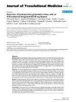
In the bubbly flow regime, as shown in Figure 4, the
maximum value of the void fraction distribution is
approximately 0.18 in the case o f the nanofluid; this
value is smaller than that of pure water, 0.225, at the cen-
ter of the tes t section. The decrease in the rate of occur-
rence of void fractions in the nanofluid becomes smaller
than that of pure water as the sensor approaches the
wall. Thus, the overall shape of the void fraction distribu-
tion was flattened more in the case of nanofluids than in
the case of pure water. The bubble velocity also
decreased in the case of the nanofluid. However, the
interfacial area concentration was in creased and it was
significant as the sensor appr oached to the wall. And the
mean bubble diameter, as determined from the void frac-
tion and interfacial area concentration, was decreased.
In the slug flow regime, as shown in Figure 5, a wider
and flatter void fraction distribution compared to that of
the pure water was also s hown in the nanofluid results.
The bubble velocity in the nanoflui d case shows a v alue
that is higher than that of the pure water case near the
center of the test section. The interfacial area concentra-
tion of the nanofluid case also shows a higher v alue
compared to the pure water. Especially in the case of
the nanofluid, the interfacial area concentration
increased significantly in the v icinity of the wall. This
can be concluded that the boundary of air slug and
liquid film is located a t this point, and t he shorter
lengths of air slugs pass the void meter in the nanofluid
case than in the pure water case. In the mean bubble
diameter result, the smaller air slug size in the nanofluid
case than that in the pure water case was evaluated as it
was reflected in the interfacial area concentration result.
Discussion
In this experiment, the void fractions were flattened
with smaller bubbles in the case of nanofluids. The
Figure 4 Comparison of the local two-phase flow parameters in the bubbly flow regime. Between the pure water and the nanofluid in the
bubbly flow regime (j
f
= 2.8294 m/s, j
g
=0.1886m/s).
Park and Chang Nanoscale Research Letters 2011, 6:284
/>Page 5 of 8
flattening of the void fraction distribution in the nano-
fluid can be explained by the forces that act between
the two phases. The types of forces that act between the
two phases include drag force, lift force, wall lubrication
force, and turbulence dispersion force. The main deter-
minant of the transverse motion of the bubbles is the
interaction between the drag force and the lift force.
For an evaluation of the drag force, the drag coeffi-
cient is derived from the Grace mode l, which is consid-
ered to be an appropriate model for sparsely distributed
fluid particles. It is expressed as
C
D
=
4
3
gd
b
U
2
T
ρ
ρ
c
(11)
The derivation of the terminal velocity, U
T
,isout-
lined in the ANSYS CFX Solver Theory Guide
(ANSYS, Inc., Canonsburg, PA, USA) [9]. To evaluate
the drag coefficient using the Grace model, mean bub-
ble diameter is the starting point. As shown in Figure
4, mean bubble diameter ranges from 0 to 0.0079 m
for the pure water and from 0 to 0.0034 m for the
nanofluid. Within this range of bubble sizes, the drag
coefficients are calculated with the fluid properties of
the pure water and the nanofluid; the results are
shown in Figure 6. The drag coefficient of the small
bubbles is about 13 to 22 in the nanofluid a nd almost
12inthepurewater.Inaddition,thedragcoefficient
of the nanofluid is larger than that of the pure water
(about 6%) within the same bubble sizes. Thus, the
drag force acting on the rising bubbles in the nanofluid
case is larger than in the pure water case.
A correlation proposed by Tomiyama [10] was used to
evaluate the effect of the lift force. A study of single
bubbles in a well-defined shear field was performed by
Tomiyama, and the correlation fo r the lift force coeffi-
cient was derived by his experiments:
C
L
=
⎧
⎨
⎩
min
0.288 tanh(0.121 Re), f(Eo
d
)
Eo
d
< 4
f (Eo
d
)for4< Eo
d
< 1
0
−0.27 10 < Eo
d
(12)
Figure 5 Comparison of local two-phase flow parameters in the slug flow regime. Between the pure water and the nanofluid in the slug
flow regime (j
f
= 1.0186 m/s, j
g
= 2.9049 m/s).
Park and Chang Nanoscale Research Letters 2011, 6:284
/>Page 6 of 8
with
f (Eo
d
) = 0.00105Eo
3
d
− 0.0159Eo
2
d
− 0.0204Eo
d
+0.47
4
(13)
This coefficient depends on the modified Eotvos num-
ber, which is given by
Eo
d
=
g(ρ
l
− ρ
g
)d
2
h
σ
(14)
The modified Eotvos number can be calculated by
using the following empirical correlation of Wellek et al.
[11] for the aspect ratio:
d
h
= d
b
3
1 + 0.163Eo
0.757
(15)
The evaluation results of the lift force are shown in
Figure 7. The negative lift coefficients of large bubbles
in pure water indicate that the lift force is acting in a
direction of t he center of the test section. Some large
bubbles in the pure water are forced to the center of the
test section, and some small bubbles in the pure water
are forced to the inner wall of the test section; together
they form a void fraction distribution with a center-
peaked shape. However, in the nanofluid case, the lift
coefficient is always positive, which means that the force
acting on the bubbles is in the direction of the inner
wall of the test section. Thus, smaller bubbles in the
nanofluid shift from the center to the wall, and the void
fraction distribut ion in this case becomes flatter than
that of the pure water case.
From these results, it can be concluded that the flat-
tened void fraction in the nanofluid means that the bub-
bles in the nanofluid smaller than those of pure water
were passed in the flow under the force acting in the
direction of the wall.
Conclusion
In this experimental study, a basic hydraulic experiment
using a water-based g-Al
2
O
3
nanofluid was conducted.
Air and the nanofluid were used as working fluids in a
vertically upward acrylic tube. The local two-phase flow
parameters such as the void fractio n, the inter facial velo-
city, the interfacial area concentration, and the mean
bubble diameter were measured using a conductivity
double-sensor two-phase void meter in bubbly and slug
flow regimes. The void fraction distribution was flattened
in the nanofluid case more than it was in t he pure water
case. The higher interfacial area concentration resulted in
a smaller mean bubble diameter in the case of the nano-
fluid. In view of the forces acting between the two phases,
the difference between the nanofluid and pure water can
be attributed to the smaller bubbles that form in the
nanofluid.
Throughout this experimental study, the characteris-
tics of the internal two-phase flow structure of the
nanofluid were specified. In addition, the heat transfer
enhancement of nanofluid can be resulted from the
increase of the interfacial area concentration w hich
refers to the available area of the mass, momentum, and
energy transfer.
Nomenclature
A cross-sectional area (m
2
)
a
i
interfacial area concentration (1/m)
C
D
drag coefficient
D inner diameter of the test section (m)
d diameter of a bubble (m)
g gravitational acceleration (m/s
2
)
j superficial velocity (m/s)
L test section length (m)
N
t
total number of bubbles that strike the sensor
Δs distance between the tips of the front and rear sen-
sor (m)
t
F1
time that a bubble starts to hit the front sensor (s)
0.001 0.002 0.003 0.004 0.005 0.006 0.007 0.008
12
16
20
Drag coefficient
Mean bubble diameter(m)
pure water
0.1% Al
2
O
3
nanofluid
Figure 6 Drag coefficient in terms of the mean bubble
diameter.
0.000 0.001 0.002 0.003 0.004 0.005 0.006 0.007 0.008 0.00
9
-0.3
-0.2
-0.1
0.0
0.1
0.2
0.3
Lift coefficient
Mean bubble diameter(m)
pure water
0.1% Al
2
O
3
nanofluid
Figure 7 Lift coefficient in terms of the mean bubble diameter.
Park and Chang Nanoscale Research Letters 2011, 6:284
/>Page 7 of 8
t
F2
time that a bubble departs from the front sensor
(s)
t
R1
time that a bubble start to hit the rear sensor (s)
Z height of the test section (m)
Α void fraction
ε energy dissipation rate per unit mass
μ viscosity (N.s/m
2
)
ν kinematic viscosity (m
2
/s)
r density (kg/m
3
)
s surface tension (N/m)
volume fraction of nanoparticle
Ω total sampling time (s)
Subscripts
f liquid phase
g gas phase
nf nanofluid
pw pure water
p nanoparticle
Authors’ contributions
YS performed the experiment and data analysis, and drafted the manuscript.
SHC conceived of this study and participated in its design and coordination
and helped to draft the manuscript. All authors read and approved the final
manuscript.
Competing interests
The authors declare that they have no competing interests.
Received: 25 November 2010 Accepted: 4 April 2011
Published: 4 April 2011
References
1. Choi SUS: Enhancing thermal conductivity of fluids with nanoparticles.
Development and Applications of Non-Newtonian Flows New York: ASME;
1995, 99-106, FED-vol. 231/MD-vol. 66.
2. Neal LG, Bankoff SG: A high resolution resistivity probe for determination
of local void properties in gas liquid flow. A.Z.Ch.E. Journal 1963,
9:490-494.
3. Walter M: Study on interfacial area transport in vertical bubbly flows.
Master’s thesis University of Karlsruhe, KAERI; 2008.
4. Mishima K, Ishii M: Flow regime transition criteria for upward two-phase
flow in vertical tubes. Int J Heat Mass Transf 1984, 5:723-737.
5. Pak BC, Cho YI: Hydrodynamic and heat transfer study of dispersed fluids
with submicron metallic oxide particles. Exp Heat Transfer 1998, 11:151.
6. Drew DA, Passman SL: Theory of Multi Component Fluids Springer-Verlag
New York, Inc. New York, NY, USA; 1999.
7. Wen D, Ding Y: Experimental investigation into convective heat transfer
of nanofluids at the entrance region under laminar flow conditions. Int J
Heat Mass Transf 2004, 47:5181.
8. Ishii M: Thermo-fluid Dynamic Theory of Two-Phase Flow Paris: Eyrolles (New
York: Scientific and Medical Publication of France); 1975.
9. ANSYS Inc: ANSYS CFX Solver Theory Guide. Release 11.0 Canonsburg; 2006.
10. Tomiyama A, Sou A, Zun I, Kanami N, Sakaguchi T: Effects of Eotvos
number and dimensionless liquid volumetric flux on lateral motion of a
bubble in a laminar duct flow. Advances in Multiphase Flow 1995, 3-15.
11. Wellek RM, Agrawal AK, Skelland P: Shapes of liquid drops moving in
liquid media. A.I.Ch.E. Journal 1966, 12:854-860.
doi:10.1186/1556-276X-6-284
Cite this article as: Park and Chang: Measurement of local two-phase
flow parameters of nanofluids using conductivity double-sensor probe.
Nanoscale Research Letters 2011 6:284.
Submit your manuscript to a
journal and benefi t from:
7 Convenient online submission
7 Rigorous peer review
7 Immediate publication on acceptance
7 Open access: articles freely available online
7 High visibility within the fi eld
7 Retaining the copyright to your article
Submit your next manuscript at 7 springeropen.com
Park and Chang Nanoscale Research Letters 2011, 6:284
/>Page 8 of 8