Báo cáo hóa học: "Preparation and characterization of carbon nanofluid by a plasma arc nanoparticles synthesis system" pot
Bạn đang xem bản rút gọn của tài liệu. Xem và tải ngay bản đầy đủ của tài liệu tại đây (3.39 MB, 11 trang )
NANO EXPRESS Open Access
Preparation and characterization of carbon
nanofluid by a plasma arc nanoparticles synthesis
system
Tun-Ping Teng
1*
, Ching-Min Cheng
1
and Feng-Yi Pai
2
Abstract
Heat dissipation from electrical appliances is a significant issue with contemporary electrical devices. One factor in
the improvement of heat dissipation is the heat transfer performance of the working fluid. In this study, we used
plasma arc technology to produce a nanofluid of carbon nanoparticles dispersed in distilled water. In a one-step
synthesis, carbon was simultaneously heated and vaporized in the chamber, the carbon vapor and particles were
then carried to a collector, where cooling furnished the desired carbon/water nanofluid. The particle size and
shape were determined using the light-scattering size analyzer, SEM, and TEM. Crystal morphology was examined
by XRD. Finally, the characterization include thermal conductivity, viscosity, density and electric conductivity were
evaluated by suitable instruments under different temperatures. The thermal conductivity of carbon/water
nanofluid increased by about 25% at 50°C compared to distilled water. The experimental results demonstrated
excellent thermal conductivity and feasibility for manufacturing of carbon/water nanofluids.
Introduction
As industrial and technological products demand higher
standards of function and capacity, the problem of heat
dissipation from electrical appliances becomes a signifi-
cant issue. To ameliorate this problem, there are four
approaches commonly taken: (1) enlarge the heat
exchanger area and structure, (2) fabricate the heat
exchanger using materials with higher therma l conduc-
tivity, (3) increase the working fluid flow rate to the
heat exchanger, and (4) improve the heat transf er per-
formance of the heat exchange working fluid. Of these
methods, enlargement of the heat exchanger area has
reached a physical limit. Increasing the flow rate of hea t
exchange would create problems of vol ume, power con-
sumption, and noise from the fan and pump. The t her-
mal conductivity of copper and al uminum heat
exchangers are quite high, and the addition of p recious
metal to improve thermal conductivity further would
incur a tremendous increase in the heat exchanger cost.
Therefore, we consider that in order to increase heat
dissipation, the most feasible approach is to improve the
heat transfer performanc e of the heat exchange working
fluid.
The use of nanofluids to improve the heat-transfer
performance of heat exchange working fluids deserves
consideration. In 1995, Choi [1] became the first person
to use the term “nanofluid” to describe a fluid contain-
ing nanoparticles. Nanofluid manufacture involves dis-
persing metallic and non-metallic nanomaterials with
high thermal conductivity, int o a suitable “ working
fluid” such as engine oil, water, ethylene glycol, etc., to
enhance the heat transfer performance of traditional
fluids [2]. According to literature reports, the thermal
conductivity of a nanofluid is strongly dependent on the
volume fraction and properties o f the add ed nanoparti-
cles [3,4]. In addition, for the addition of a given volume
of particles, the solid-liquid surface contact area between
nano-scale particles and the suspension fluid is greater
than that for micro-scale particles. Hence, the size and
shape of the particles added will have a significant effect
on thermal conductivity and heat transfer characteristics
[1,5-12].
Nanofluids preparation generally follows one of two
methods: a one-step and a two-step synthesis. The so-
called “ one-step synthesis” produces nanofluids by
synthesizing the nanoparticles directly into a suspending
* Correspondence:
1
Department of Industrial Education, National Taiwan Normal University, No.
162, Sec. 1, He-ping E. Rd., Da-an District, Taipei City 10610, Taiwan
Full list of author information is available at the end of the article
Teng et al. Nanoscale Research Letters 2011, 6:293
/>© 2011 Teng et al; licensee Springer. This is an Open Access article distributed under the terms of the Creative Commons Attribution
License ( which permits unrestri cted use, distribution, and reproduction in any medium,
provided the original work is properly cited.
fluid, while the two- step process produces the nanopar -
ticles and then disperses them in a bulk liquid to form a
stable suspension, as separate processes.
Many variations on the one -step synthesis of nano-
fluids exist. Akoh et al. [13] used the VEROS method to
prepare nanofluids in a one-step by applying vacuum
evaporation to a running oil substrate. Wagener et al.
[14] adopted magnetron sputtering to improve the
VEROS technique, and succeeded in developing an
effective preparation of Ag, Fe nanofluids. Zhu et al.
[15] employed a new chemical method to prepare Cu-
ethylene glycol nanofluids from reaction under micro-
wave irradiation. Eastman et al. [16] also improved on
the VEROS technique, by using low-temperature and
low-pressure conditions, and letting Cu vapor directly
contact and flow with low-vapor-pressure ethylene gly-
col fluid, causing the Cu vapor to condense directly in
the fluid to form Cu nanofluid. Lo et al.[17]useda
submerged arc nanoparticle-synthesis system to prepare
Cu-based nanofluids. Lo et al. let Cu vapor, formed
by electric arc discharge, directly condense in low-
temperature and l ow-pressure deionized water, or ethy-
lene glycol, to form CuO and Cu nanofluids. These
researchers also used this method t o produce Ni nano-
magnetic fluids [18], and achieved good results. Chang
et al. [19] synthesized an Al
2
O
3
nanofluid, with high
suspension stability, using a modified plasma arc system.
The vaporized metallic gas mixed thoroughly with the
pre-condensed, deionized water, to form an Al
2
O
3
/water
nanofluid. The average particle size was in the range
25-75 nm. Hwang et al. [20] employed a modified mag-
netron sputtering system to produce Ag/silico n oil
nanofluids. The Ag nanoparticles were relatively uni-
form with primary size less than 5 nm. Kumar et al.
[21] fabricated copper nanofluids, of metallic copper dis-
persed in ethylene glycol, using s odium hypophosphite
as reducing agent and conventional heating. Wei et al.
[22] applied chemical solution methods to synthesize
cuprous-oxide (Cu
2
O) nanoparticles in water, to form
Cu
2
O nanofluids. Abareshi et al. [ 23] produced magne-
tite Fe
3
O
4
nanoparticles by a co-precipitation method at
various pH values. The concentration was around
0.25-3.0 vol.%. Generally, the one-step synthesis has the
advantage that nanoparticles form directly in the bulk
liquid. Normally, this method contains an intrinsic sort-
ing mechanism, in which excessively large particles set-
tle by static placement, and the supernatant, containing
finer nano-sized particles as the dispersion, simply col-
lected. This approach provides nanofluids with good
suspension properties. Unless required by the prepara-
tion process, there is no need to add any dispersant or
surfactant to improve the dispersion, and thus, not
interference will arise from the addition of such addi-
tives. However, a disadvantage of the one-step method
is that preparation conditions influence the size, shape
and concentration of nanoparticles, the range of particle
size distribution is broad, and an accurate control of the
concentration is difficult.
Considering reports of two-step nanofluid formation,
there are many accounts of Al
2
O
3
nanofluid preparation
using ultrasonic dispersion [16,24,25]. Murshed et al.
[26] employed ultrasonic dispersion to prepare TiO
2
/
water nanofluid, and applied the same method to prepare
Au, Ag, SiC, and carbon nanotube nanofluid. In general,
two-step syntheses are more suitable for the preparation
of oxide nanofluids, but are less appropriate for the pre-
paration of metallic nanofluids. Wen and Ding [27] used
a high shear homogenizer to solve an agglomeration pro-
blem with T iO
2
nanoparticles. Operating the homogeni-
zer at 24,000 rpm, with a shear rate of 40,000 s
-1
disrupted nanoparticle agglomera tion and provided an
adequate dispersion of nanoparticles with narrow size
distribution. Never theless, although this method
improved on the agglomeration problem, it was still una-
vailabletoacquiretheparticlesizeasobservedbySEM
and TEM. Choi et al.[28]usedZrO
2
bead milling in a
vertical, super-fine grinding mill, to mix Al
2
O
3
and AlN
with transformer oil at volume fractions up to 4%, and
added n-hexane to regard as d ispersant in order to keep
good suspension. Hwang et al. [20] treated carbon black
(CB)/water, and Ag/silicon oil nanofluids, to various two-
step procedures, using stirrer, ultrasonic bath, u ltrasonic
disrupter and high-pressure homogenizer methods in
order to achieve small particle size, with good dispersion.
The high-pressure homogenizer produced average CB
and Ag particle diameters of 45 and 35 nm, respectively.
Moosavi et al. [29] demonstrated a two-step synthesis of
ZnO nanoparticles, by mixing ethylene glycol and gly-
cerol with the aid of a magnetic stirrer. Moosavi et al.
added ammonium citrate to act as a dispersant, and
enhance stability of the suspension. This method p ro-
duced a mean ZnO particle size of 67.17 nm.
Generally, two-step methods are simpler than one-step
methods, because the nanoparticles may either be self-
made, or purchased, then added to a bulk liquid to form
nanofluids. However, in the process of addition, agglom-
eration can occur easily, resulting in poor suspension,
thus, two-step methods often require dispersion meth-
ods such as ultrasonic sonication, mechanical stirring, a
homogenizer, or the addition of a surfactant or disper-
sant, to disrupt agglomeratio n and provide dispersion
and stabilize the suspension. The advantages of two-step
syntheses are facile and rapid preparation of large
volume nanofluids, greater control over nanoparticle
concentration and narrower particle size distribution is
than that of single-step syntheses.
In this study, we employed a plasma arc system to pro-
duce a carbon/water nanofluid with stable suspension, in a
Teng et al. Nanoscale Research Letters 2011, 6:293
/>Page 2 of 11
one-step process, without addition of any dispersant or
surfactant. We fully characterized the microstructure, par-
ticle size distribution, and fundamental properties by suita-
ble instrumentation, in order to demonstrate the feasibility
of the process described herein.
Preparation of carbon/water nanofluid by plasma
arc
The carbon/water nanofluid in this study was prepared
by the plasma arc system [19], which belongs to one-
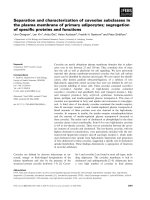
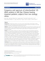
step synthesis system. Figure 1 shows a schematic layout
of the carbon/water nanofluid synthesis. Plasma arc
welding equipment (400 GTS, Thermal Arc, Therma-
dyne, St. Louis, MO, USA) provided the heat source,
and a vaporization chamber, cooling system, and collec-
tion system completed the system. The plasma arc pro-
vided the extreme high temperature inside the
vaporizatio n chamber , which melted and evaporated the
graphite rods. Using this setup, we could control for
working current, pulse frequency, and plasma gas and
argon (Ar) carrier-gas flow rates. The pressure differen-
tial produced between the vaporization chamber and
collection chamber induces vaporized carbon to move
into the collection chamber. The nanofluid collection
system and cooling system pre-cools distilled water to
maintain a constant 3-5°C during the collection of
nanoflui d and to further suppress excess particle growth
and clustering.
The low temperature of the working liquid (distilled
water) instantly condenses the vaporized carbon to form
nanoparticles, and the magnetic stirrer and stainless
steel mesh thoroughly mix the resulting nanofluid,
which will be induced out to form stable carbon/water
nanofluid by collection pipe. Carbon nanoparticles sus-
pended in cold distilled water have fewer interactions,
so less aggregation occurs, resulting in smaller nanopar-
ticles. Finally, we conducted an examination of the col-
lected nanofluids material properties.
Method and procedure for characteristic
experiments
Experimental procedure
All the completed experimental samples had to be stati-
cally placed for 48 h to confirm suspension perfor-
mance, and to be identified concentration of carbon/
water nanofluid changes less than 5% in a fixed depth of
the container by using the spectrometer. For the particle
size analysis, we used transmission electron microscope
(FEI-TEM, Tecnai G
2
F20, Philips, Holland, the Nether-
lands) and a field emission scanning electron micro-
scope(FE-SEM,1530,LEO,CarlZeissSmtLtd.,
Cambridge, UK) to identify microstructural properties.
a
b
Figure 1 Schematic diagram of the synthesis system for carbon/water nanofluid. (a) The synthesis system for carbon/water nanofluid.
(b) The vaporization chamber in the synthesis system.
Teng et al. Nanoscale Research Letters 2011, 6:293
/>Page 3 of 11
The suspended particle size and zeta potential of car-
bon/water nanofluids were measured using a light-
scattering size/zeta potential analyzer (Zetasizer Nano
ZS, Malvern Instruments, Worcestershire, UK) so as to
determine clustering and suspension performance.
Regarding the analysis of materials, the dry nanoparti-
cles were obtained by centrifuge and heating the nano-
fluid to the appropriate speed and temperature. The
crystalline phase was determined by X-ray Diffraction
(XRD,APEXII,KappaCCD,Monrovia,CA,USA).All
peaks were measured by XRD and assigned by compari-
son with those of the joint committee on powder dif-
fraction standards data (PCPDFWIN 2.4, JCPDS-ICDD,
Newtown Square, PA, USA) [30]. Density, electric con-
ductivity, viscosit y, and thermal conductivities were
measured by a density meter (DA-130N, KEM, Tokyo,
Japan), rheology meter (DVIII+, BROOKFIELD, Middle-
boro, MA, USA), electric conductivity meter (CD-4306,
Lutron Electronics Co., Inc., Taipei, Taiwan) respec-
tively, and a thermal property analyzer (KD-2 Pro, Deca-
gon Devices, Inc., Pullman, WA, USA) was used for
determination of carbon/water nanofluids properties at
various temperatures.
Data analysis
The weight fraction (ω) of the carbon/water nanofluid is
given by Eq. 1, with bulk fluid density (r
bf
), nanoparticle
density (r
p
), and nanofluid density (r
nf
) [4,31]:
ω =
ρ
bf
ρ
p
−
ρ
nf
ρ
p
ρ
nf
ρ
bf
− ρ
nf
ρ
p
(1)
The volume fraction (j) of the carbon/water nanofluid
is given by Eq. 2, with bulk fluid weight (W
bf
), nanopar-
ticle weight (W
p
), and nanofluid weight (W
nf
):
φ =
(W
p
/ρ
p
)
(W
nf
/ρ
nf
)
= ω
ρ
nf
ρ
p
(2)
Equation 2 can be used to convert the weight fraction to
volume fraction in order to compare the experimental
results with the relevant literatures. However, it should be
noted that the density is affected by temperature, so the
volume fraction will be slightly changed by temperature.
For easy comparison of experimental data after chan-
ging the carbon/ water nanofluid (D
nf
), all data obtained
with the distilled water is used as baseline values (D
bf
);
that is, experimental data obtained after the carbon/
water nanofluid i s used to compare with baseline values.
The differences before and after changing the carbon/
water nanofluid is presented as pr oportions (R), it can
be calculated as follows:
R =
(
D
nf
− D
bf
)
/D
bf
× 100
%
(3)
Uncertainty analysis
In this study, the uncertainty of the experimental prop-
erties results was determine from the measurement
deviation of the parameters, such as density, viscosity,
electric conductivity, thermal conductivity, weight and
temperature , as described by Kulkarni et al. [32]. In the
density experiment, the density was determined from
readings of the density meter (r
t
), resistance t empera-
ture detector (RTD, pt-100) of isothermal unit (T).
u
m,ρ
=
ρ
t
/ρ
t
2
+
T/T
2
(4)
The precision of the density meter was ±1%. The pre-
cision of the RTD was ±0.5°C. Hence, the uncertainty of
the density experiment was less than ±2.7%.
In the viscosity experiment, the viscosity was deter-
mined from readings of the rheology meter (μ
t
), RTD
(pt-100) of isothermal unit (T).
u
m,μ
=
μ
t
/μ
t
2
+
T/T
2
(5)
The precision of the rheology meter was ±1%. The
precision of the RTD was ±0.5°C. Hence, the uncertainty
of the viscosity experiment was less than ±2.7%.
In the electric conductivity experiment, the electric
conductivity was determined from readings of the rheol-
ogy meter (e
t
), RTD (pt-100) of isothermal unit (T).
u
m,e
=
e
t
/e
t
2
+
T/T
2
(6)
The precision of the electric conductivity meter was
±3%. The precision of the RTD was ±0.5°C. Hence, the
uncertainty of the electric conductivity experiment was
less than ±3.9%.
In the thermal conductivity experiment, the thermal
conductivity was determined from readings of the ther-
mal property analyzer (k
t
), RTD (pt-100) of isothermal
unit (T).
u
m,k
=
k
t
/k
t
2
+
T/T
2
(7)
The precision of the thermal property analyzer was
±5%. The precision of the RTD was ±0.5°C. Hence, the
uncertainty of the thermal conductivity experiment was
less than ±5.6%.
Results and discussion
We maintained the working currents at 70 A (NC-70)
and 80 A (NC-80). Table 1 li sts the fabrication para-
meters and partial experimental and calculated results
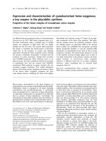
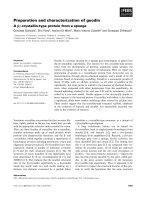
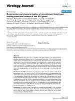
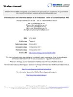
for the carbon/water nanofluid. Figures 2 and 3 are
respectively the SEM and TEM photographs of carbon
nanoparticles. From the figures, these can show that the
Teng et al. Nanoscale Research Letters 2011, 6:293
/>Page 4 of 11
nanoparticles are irregular in shape, and the nanoparti-
cles occurred in an aggregate phen omenon. In addit ion,
Figure 3c, d is the TEM photograph for the edge of car-
bon nanoparticles. The thickness of carbon nanoparti-
cles is much smaller than its length and width in the
photographs. Overall, the shape of these nanoparticles is
of the shape of flakes (d-Spacing about 0.35 nm).
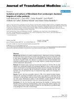
This study used the light-scattering size/zeta potential
analyzer to determine the average nanoparticle size
when suspended in distilled water. Figure 4 shows the
particle size distribution for the carbon nanoparticles
suspended in distilled water. Table 1 shows that for
nanofluids at a working current of 70 A, the z-average
particle size is 244.4 nm and the zeta potential is
-24.4 mV. The distribution only has a s ingle-peak, and
dispersion is good. For nanofluids with a working
current of 80 A, the z-average particle size is 284.6 nm,
and a double-peak distribution appears at 298.9 and
4,590 nm. The zeta potential is -21 mV. From the distri-
bution of measured values, we see that the secondary
part icle size is far greater than the primary particle size,
as measured by SEM and TEM. This is mainly because
agglomeration continues to occur to the suspended
nanoparticles in distilled water and the tested particle
size is greater than the particle size as observed by SEM
and TEM.
Figure 5 shows XRD patterns of the carbon nanoparti-
cles obtained by centrifuging and heating of the nano-
fluids. We found that the major component of both the
NC-70 and NC-80 fluids was carbon by comparing with
PCPDFWIN data (PDF#460945) [30]. The diffraction
peak intensity is not high, so the major structure of
nanoparticles should belong to the multi-layer sheet of
amorphous carbon. Therefore, changes in the process
parameters did not significantly affect the materials’
crystallization phase. Also, from the TEM diffraction
patterns (Figure 6) of these carbon nanoparticles, non-
crystalline structure can be seen.
Figure 7 shows changes in the density ratio of carbon/
water nanofluids to that of distilled water at various
temperatures. Between the enhanced ratio of density
and the temperature difference, there is no obvious
trend in the ratio due to heating, mainly because the
nanofluid is a solid-liquid mixture. The thermal expan-
sion rate of the bulk liquid is different from that of the
nanoparticles, thus providing an inconsistent trend in
den sity change. The density of carbon was measure d by
Table 1 List of fabrication parameters and properties for
carbon/water nanofluid
Name NC-70 NC-80
Working currents (A) 70 80
Working voltage (V) 24.3~24.7 26.2~26.8
Working power (kW) 1.70~1.73 2.10~2.15
Pulse frequency (Hz) 25 25
Plasma Ar (L/min) 1.5
Shield Ar (L/min) 9
Carrier-gas/Ar (L/min) 18
Distilled water volume (ml) 500
Manufacturing time (s) 1,000
Particle size (Z-average, nm)
a
244.4 284.6
Zeta potential (mV)
a
-24.4 -21.2
Concentration (wt.%)
a
0.02 0.04
a
Data are measured and calculated at 25°C.
a
b
Figure 2 SEM image of carbon nanoparticles. (a) NC-70, (b) NC-80.
Teng et al. Nanoscale Research Letters 2011, 6:293
/>Page 5 of 11
weighing after drying at fixed weight o f nanofluid
and calculated by Eq. 1, and the density of carbon nano-
particles was about 1,900 kg/m
3
to approximately
2,050 kg/m
3
. For a concentration of about 0.02 wt.%
(NC-70) and a temperature in the range of 20-50°C, the
density increases by 0.01-0.39%. For a concentration of
about 0.04 wt.% (NC-80), the increase in density is 0.02-
0.50%. The minimum increase in density ratios for both
samples occurs at 30°C. The scope of the experimental
deviation i s limited because density change is not
obvious.
The viscosity of the carbon/water nanofluid as a func-
tion of shear rate, between 20°C and 50°C is shown in
Figure 8. The viscosity of the carbon/water nanofluid is
dependent on the shear rate over the entire measured
temperature range. The addition of as little as 0.02 wt.%
(NC-70) or 0.04 wt.% (NC-80) carbon n anoparticles to
the distilled water results in carbon/water nanofluid
a
b
c
d
Figure 3 TEM image of carbon nanoparticles. (a) NC-70, (b) NC-80, (c) Edge of NC-70, (d) Edge of NC-80.
Figure 4 Particle size distribution of carbon/water nanofluid.
Teng et al. Nanoscale Research Letters 2011, 6:293
/>Page 6 of 11
displaying non-Newtonian behavior (shear thinning).
Carbon/water nanofluids display Newtonian behavior
with higher shear rate (S
R
>350 s
-1
), but the temperature
of NC-80 is greater than 40°C. Additionally, the rheolo-
gical properties of carbon/water nanofluid approach
Newtonian behavior and increase carbon/water nano-
fluid concentrations at low temperatures. This trend
occurs because viscosity reduces as water temperatures
increase, so the added nanoparticles will increase the
fluid internal shear stresses that results to the observed
nanofluid viscosity. Adding more nanoparticles would
produceasimilareffect.Figure9showsthechangein
viscosity ratio for carbon/water nanofluids compared to
distilled water at various temperatures and under differ-
ent process parameters. In general, nanofluid viscosity
increases with increasing nanoparticle loading in the
bulk liquid. For an NC-70 concentration of 0.02 wt.%
and within a temperature range of 20-50°C, the viscosity
ratio increases by 7.77-15.17%. For an NC-80 concentra-
tion of 0.04 wt.%, the viscosity ratio increases by 15.76-
31.63%. In addition, Figure 9 shows the calculated
results of Einstein’s model [33] (Eq. 8) in comparison
with the experimental results that show a serious under-
estimation, which may be results from the material
properties and aggregation of carbon nanoparticles [34].
From the abov e results, it can be found that the viscos-
ity of c arbon/wat er nanofluid is much higher than that
of the water. When the carbon/wat er nanofluid was
applied to heat exchange, pressure drop of pipeline and
energy consumption of pump-related issues must be
considered in particular in the future.
μ
nf
μ
bf
=1+2.5
φ
(8)
Figure 10 shows the change in ratio of the nanofluid
electric conductivity to distilled water at different tem-
peratures. There is no dramatic change observed in elec-
trical conductivity over the temperature test range of
Figure 5 X-ray diffraction pattern of carbon nanoparticles.
ab
Figure 6 TEM diffraction patterns of carbon nanoparticles. (a) NC-70, (b) NC-80.
Teng et al. Nanoscale Research Letters 2011, 6:293
/>Page 7 of 11
30°C, since the temperatu re range is small. When the
NC-70 concentration is 0.02 wt.% and the temperature
of carbon/water nanofluid is in the range of 20-50°C,
the change in electric conductivity ratio increases by
6.48-12.10%. For an NC-80 concentration of 0.04 wt.%,
the change in electric conductivity ratio increases by
25.37-36. 71%. The minimum enhanced ratios of electric
conductivity for the two samples occur at 50°C. Com-
paring the experimental results with literature, this
study used the model of Cruz et al. [35] modified from
Maxwell’ s model [36] for analysis and comparison.
Because the electric conductivity of carbon is much
higher than that of the distilled water and that a is
greater than one (a =(e
p
/e
bf
) ≫ 1), the principle
of highly conducting particles (Eq. 9) is chosen to be
compared with the experimental results of this study.
Figure 10 shows a considerable underestimation while
comparing calculation results with experimental data
under most conditions. Because the Maxwell’ smodel
[36] is suitable only for fluids with large-size (micro-
meter or millimeter) particles dispersing [37-39], under-
estimation of the conductivity increases in nanofluid.
Apart from the concentration and electric conductivity of
particles and fluids, the effective electrical conductivity of
nanoflui ds exhibits a complex dependence on the electri-
cal double layer interactions [40,41], ionic concentra-
tions, and other physicochemical properties which is not
effectively captured b y the Maxwell’ s model. Further-
more, this phenomenon of underestimation may result
from the lower solid-liquid interface resistance due to
high surface wetting of car bon nanoparticles by one-step
synthesis, which results in the electric conductivity of
carbon/water nanofluids with a higher enhancement.
e
nf
e
b
f
=1+3
φ
(9)
Figure 7 Dependence relationship between te mperatures and
density enhanced ratio of carbon/water nanofluid under
different fabrication parameters.
a
b
Figure 8 Dependence relationship between shear rate and viscosity of carbon/water nanofluid under different temperatures. (a) NC-70,
(b) NC-80.
Teng et al. Nanoscale Research Letters 2011, 6:293
/>Page 8 of 11
Figure 11 shows the change in thermal conductivity
ratio for nanofluid compared to distilled water, over a
temperature range of 20-50°C. The figure reveals that as
the temperature increases, the effect of increasing nano-
particle concentration on the thermal conductivity ratio
is greater than the applied temperature change. Increas-
ing both concentration and temperature increases the
frequency of particle liquid collisions producing a near
quasi-convection phenomenon. Increasing random colli-
sion behavior helps to increase the thermal conduct ivity
of carbon/water nanofl uids, but there are some
researchers who believe that the above-mentioned
factors to increase the thermal conductivity were not
significant [42,43]. For a concentration of 0.02 wt.%
(NC-70) and a temperature in the range of 20-50°C, the
ratio of thermal cond uctivity increases by 5.0-17.54%.
For a concentration of 0.04 wt.% (NC-80), the ratio of
thermal conductivity increases by 7.78-25.0% compared
to distilled water.
In addition, Figure 11 shows an underestimation (Eq.
10) between the Maxwell’s model [36] and the experi-
mental results. This is because the Maxwell’smodel
only considers the spherical and larger particles with the
volume fraction of particles added, liquid and solid ther-
mal conductivity on thermal conductivity of nanofluid,
and cannot cover all factors. Since this study is made of
non-spherical carbon nanoparticles, Maxwell’sequation
will show an undervalue. Moreover, this study found
that low concentrations of added nanoparticles caused
by the thermal conducti vity increase should be from the
interfacial thermal resistance and the aspect ratio of the
dispersed particles [43-45] . Since the carbon/ water
nanofluids was manufactured by one-step synthesis in
this study, non-spherical carbon nanoparticles were dis-
persed in the water and condensation occurred, s o the
interfacial thermal resistance should be relatively low
due to high surface wetting of carbon nanoparticles
which can effectively enhance the thermal conductivity
of carbon/water nanofluid. Furthermore, the carbon
nanoparticles made in this study are flake shaped, in
which the thickness of the nanoparticle is much smaller
than the length and width respectively, and thus adding
Figure 9 Dependence relationship between te mperatures and
viscosity enhanced ratio of carbon/water nanofluid under
different fabrication parameters.
Figure 10 Dependence relationship between temperatures and
electric conductivity enhanced carbon/water nanofluid ratio
under different fabrication parameters.
Figure 11 Dependence relationship between temperatures and
thermal conductivity enhanced carbon/water nanofluid ratio
under different fabrication parameters.
Teng et al. Nanoscale Research Letters 2011, 6:293
/>Page 9 of 11
such nanoparticle to t he liquid can increase the thermal
conductivity of nanofluids [26,46].
k
nf
k
b
f
=
k
p
+2k
f
+2φ(k
p
− k
f
)
k
p
+2k
f
− φ(k
p
− k
f
)
(10)
Conclusions
Using plasma arc in a one-step synthesis successfully
produced a carbon/water nanofluid. The resulting nano-
fluid displayed good suspension performance, and the
addition of dispersan ts was unnecessary. Characteriza-
tion included thermal conduct ivity, viscosity, density,
and electric conductivity measurements at various tem-
peratures. The thermal conductivity of the carbon/water
nanofluid is increased to about 25% at 50°C compared
to distilled water. In addition, the manufacturing
machine has the potential to produce the nanofluid with
a variety of materials in the future. In the aspect of opti-
mal manufacturing parameters for nanofluid, it is worth
having a further in-depth study.
Acknowledgements
The authors would like to thank National Science Council of the Republic of
China, Taiwan for their financial support to this research under contract no.
NSC 99-2221-E-003-006- and NSC 99-2221-E-003-008
Author details
1
Department of Industrial Education, National Taiwan Normal University, No.
162, Sec. 1, He-ping E. Rd., Da-an District, Taipei City 10610, Taiwan
2
Department of Mechatronic Technology, National Taiwan Normal University,
No. 162, Sec. 1, He-ping E. Rd., Da-an District, Taipei City 10610, Taiwan
Authors’ contributions
TPT and CMC designed the experiment. CMC and FYP fabricated the
sample. TPT and CMC carried out the measurements. TPT analyzed the
measurements. TPT and CMC wrote the paper. All authors read and
approved the final manuscript.
Competing interests
The authors declare that they have no competing interests.
Received: 29 October 2010 Accepted: 5 April 2011
Published: 5 April 2011
References
1. Choi SUS: Enhancing thermal conductivity of fluids with nanoparticles. In
ASME FED. Volume 231. Edited by: Siginer DA, Wang HP. Developments and
Applications of Non-Newtonian Flows; 1995:99.
2. Chang LD, Mou CM: Nanomaterials and Nanostructure Peking: Science Press;
2001.
3. Xuan Y, Li Q: Heat transfer enhancement of nanofluids. Int J Heat Fluid
Flow 2000, 21:58.
4. Eastman JA, Choi SUS, Li S, Yu W, Thompson LJ: Anomalously increased
effective thermal conductivities of ethylene glycol-based nanofluids
containing copper nanoparticles. Appl Phy Lett 2001, 78:718.
5. Choi SUS, Zhang ZG, Yu W, Lockwood FE, Grulke EA: Anomalous thermal
conductivity enhancement in nano-tube suspensions. Appl Phy Lett 2001,
79:2252.
6. Xie H, Wang J, Xi T, Liu Y, Ai F, Wu Q: Thermal conductivity enhancement
of suspensions containing nanosized alumina particles. J Appl Phys 2002,
91:4568.
7. Xuan Y, Li Q: Investigation on Convective Heat Transfer and Flow
Features of Nanofluids. J Heat Transf Trans ASME 2003, 125:151.
8. Chopkar M, Das PK, Manna I: Synthesis and characterization of nanofluid
for advanced heat transfer applications. Scr Mater 2006, 55:549.
9. Williams W, Buongiorno J, Hu LW: Experimental investigation of turbulent
convective heat transfer and pressure loss of alumina/water and
zirconia/water nanoparticle colloids (nanofluids) in horizontal tubes.
J Heat Transf Trans ASME 2008, 130:1.
10. Duangthongsuk W, Wongwises S: Heat transfer enhancement and
pressure drop characteristics of TiO2-water nanofluid in a double-tube
counter flow heat exchanger. Int J Heat Mass Trans 2009, 52 :2059.
11. Teng TP, Hung YH, Teng TC, Mo HE, Hsu HG: The Effect of Alumina/Water
Nanofluid Particle Size on Thermal Conductivity. Appl Therm Eng 2010,
30:2213.
12. Godson L, Raja B, Mohan Lal D, Wongwises S: Enhancement of heat
transfer using nanofluids–An overview. Renew Sust Energ Rev 2010, 14:629.
13. Akoh H, Tsukasaki Y, Yatsuya S, Tasaki A: Magnetic properties of
ferromagnetic ultrafine particles prepared by vacuum evaporation on
running oil substrate. J Cryst Growth 1978, 45:495.
14. Wagener M, Murty BS, Gunther B, Pittsburgh PA: Preparation of metal
nanosuspensions by high-pressure D C-sputter ing on run ning liquids.
In Na nocr ysta lline and Nanocomp osit e Materials II, 457. Mater ials
Research Society Edited by: Komarnenl S, Parker JC, Wollenberger HJ
1997, 149.
15. Zhu H, Lin Y, Yin Y: A novel one-step chemical method for preparation of
copper nanofluids. J Colloid Interface Sci
2004, 227:100.
16.
Eastman JA, Choi SUS, Li S, Thompson LJ, Lee S: Enhanced thermal
conductivity through the development of nanofluids, in Nanophase and
Nanocomposite Materials II. In Mater Res Soc Symp Proc Edited by:
Komarneni S, Parker JC, Wollenberger HJ 1997, 457:9.
17. Lo CH, Tsung TT, Chen LC: Shape-controlled synthesis of Cu-based
nanofluid using submerged arc nanoparticle synthesis system (SANSS). J
Cryst Growth 2005, 277:636.
18. Lo C, Tsung TT, Chen LC: Ni nano-magnetic fluid prepared by submerged
arc nano synthesis system (SANSS). JSME Int J Ser B: Fluids Therm Eng
2006, 48:750.
19. Chang H, Chang YC: Fabrication of Al2O3 nanofluid by a plasma arc
nanoparticles synthesis system. J Mater Process Technol 2008, 207:193.
20. Hwang Y, Lee JK, Lee JK, Jeong YM, Cheong SI, Ahn YC, Kim SH:
Production and dispersion stability of nanoparticles in nanofluids.
Powder Technol 2008, 186:145.
21. Ananda Kumar S, Shree Meenakshi K, Narashimhan BRV, Srikanth S,
Arthanareeswaran G: Synthesis and characterization of copper nanofluid
by a novel one-step method. Mater Chem Phys 2009, 113:57.
22. Wei X, Zhu H, Kong T, Wang L: Synthesis and thermal conductivity of
Cu2O nanofluids. Int J Heat Mass Tran 2009, 52:4371.
23. Abareshi M, Goharshadi EK, Zebarjad SM, KhandanFadafan H, Youssefi A:
Fabrication, characterization and measurement of thermal conductivity
of Fe3O4 nanofluids. J Magn Magn Mater 2010, 322:3895.
24. Lee S, Choi SUS, Li S, Eastman JA: Measuring thermal conductivity of
fluids containing oxide nanoparticles. J Heat Trans 1999, 121:280.
25. Wang X, Xu X, Choi SUS: Thermal conductivity of nanoparticle-fluid
mixture. J Thermophys Heat Trans 1999, 13:474.
26. Murshed SMS, Leong KC, Yang C: Enhanced thermal conductivity of TiO2-
water based nanofluids. Int J Therm Sci 2005, 44:367.
27. Wen D, Ding Y: Natural Convective Heat Transfer of Suspensions of
Titanium Dioxide Nanoparticles (Nanofluids). IEEE Trans Nanotechnol 2006,
5:220.
28. Choi C, Yoo HS, Oh JM: Preparation and heat transfer properties of
nanoparticle-in-transformer oil dispersions as advanced energy-efficient
coolants. Curr Appl Phys 2008, 8:710.
29. Moosavi M, Goharshadi EK, Youssefi A: Fabrication, characterization, and
measurement of some physicochemical properties of ZnO nanofluids. Int
J Heat Fluid Flow
2010, 31:599.
30.
JCPDS-ICDD: The International Centre for Diffraction Data. PCPDFWIN 2.4
2003.
31. Liu ZH, Zhu QZ: Application of aqueous nanofluids in a horizontal mesh
heat pipe. Energy Conv Manag 2011, 52:292.
32. Kulkarni DP, Namburu PK, Bargar HE, Das DK: Convective heat transfer and
fluid dynamic characteristics of SiO2-ethylene glycol/water nanofluid.
Heat Transfer Engineering 2008, 29:1027.
33. Einstein A: Investigations on the theory of the Brownian movement New York:
Dover Publications; 1956.
Teng et al. Nanoscale Research Letters 2011, 6:293
/>Page 10 of 11
34. Prasher R, Song D, Wang J: Measurements of nanofluid viscosity and its
implications for thermal applications. Appl Phys Lett 2006, 89:133108.
35. Cruz RCD, Reinshagen J, Oberacker R, Segadaes AM, Hoffmann MJ:
Electrical conductivity and stability of concentrated aqueous alumina
suspensions. J Colloid Interface Sci 2005, 286:579.
36. Maxwell JC: In A treatise on electricity and magnetism. Volume 1. 3 edition.
Oxford: Clarendon; 1904.
37. Turner JCR: Two-phase conductivity: The electrical conductance of liquid-
fluidized beds of spheres. Chem Eng Sci 1976, 31:487.
38. Meredith RE, Tobias CW: Conductivities in emulsions. J Electrochem Soc
1961, 108:286.
39. Ganguly S, Sikdar S, Basu S: Experimental investigation of the effective
electrical conductivity of aluminum oxide nanofluids. Powder Technol
2009, 196:326.
40. Hunter RJ: Zeta potential in colloid science, Principles and Applications
London: Academic Press; 1981.
41. Lyklema J: In Fundamentals of Interface and Colloid Science. Volume 1.
London: Academic Press; 1991.
42. Keblinski P, Phillpot SR, Choi SUS, Eastman JA: Mechanisms of heat flow in
suspensions of nano-sized particles (nanofluids). Int J Heat Mass Trans
2002, 45:855.
43. Buongiorno J, Venerus DC, Prabhat N, McKrell T, Townsend J,
Christianson R, Tolmachev YV, Keblinski P, Hu LW, Alvarado JL, Bang IC,
Bishnoi SW, Bonetti M, Botz F, Cecere A, Chang Y, Chen G, Chen H,
Chung SJ, Chyu MK, Das SK, di Paola R, Ding Y, Dubois F, Dzido G, Eapen J,
Escher W, Funfschilling D, Galand Q, Gao J, et al: A benchmark study on
the thermal conductivity of nanofluids. J Appl Phys 2009, 106:094312.
44. Nan CW, Birringer R, Clarke DR, Gleiter H: Effective thermal conductivity of
particulate composites with interfacial thermal resistance. J Appl Phys
1997, 81:6692.
45. Cherkasova AS, Shan JW: Effective conductivity of dispersions: The effect
of resistance at the particle surfaces. J Heat Trans 2010, 132:082402.
46. Jwo CS, Teng TP, Chang H: A simple model to estimate thermal
conductivity of fluid with acicular nanoparticles. J Alloy Compd 2007,
434:569.
doi:10.1186/1556-276X-6-293
Cite this article as: Teng et al .: Preparation and characterization of
carbon nanofluid by a plasma arc nanoparticles synthesis system.
Nanoscale Research Letters 2011 6:293.
Submit your manuscript to a
journal and benefi t from:
7 Convenient online submission
7 Rigorous peer review
7 Immediate publication on acceptance
7 Open access: articles freely available online
7 High visibility within the fi eld
7 Retaining the copyright to your article
Submit your next manuscript at 7 springeropen.com
Teng et al. Nanoscale Research Letters 2011, 6:293
/>Page 11 of 11