Báo cáo hóa học: "Transmission electron microscopic observations of nanobubbles and their capture of impurities in wastewater" potx
Bạn đang xem bản rút gọn của tài liệu. Xem và tải ngay bản đầy đủ của tài liệu tại đây (2.93 MB, 9 trang )
NANO EXPRESS Open Access
Transmission electron microscopic observations
of nanobubbles and their capture of impurities
in wastewater
Tsutomu Uchida
1*
, Seiichi Oshita
2
, Masayuki Ohmori
3
, Takuo Tsuno
4
, Koichi Soejima
5
, Satoshi Shinozaki
5
,
Yasuhisa Take
6
and Koichi Mitsuda
6
Abstract
Unique properties of micro- and nanobubbles (MNBs), such as a high adsorption of impurities on their surface, are
difficult to verify because MNBs are too small to observe directly. We thus used a transmission electron microscope
(TEM) with the freeze-fractured replica method to observe oxygen (O
2
) MNBs in solutions. MNBs in pure water and
in 1% NaCl solutions were spherical or oval. Their size distribution estimated from TEM images close to that of the
original solution is measured by light-scattered methods. When we applied this technique to the observation of O
2
MNBs formed in the wastewater of a sewage plant, we found the characteristic features of spherical MNBs that
adsorbed surrounding impuri ty particles on their surface.
PACS: 68.03 g, 81.07 b, 92.40.qc
Introduction
Small bubbles, such as microbubbles (MBs; usually
range from 10
-4
to 10
-6
m in diameter) and nanobubbles
(NBs; less than 10
-6
m in diameter), have various prop-
erties that differ from macroscopic bubbles (greater than
10
-3
m in diameter). For example, smaller bubbles have
lower buoyancies, so they take longer to reach the liquid
surface and thus they have longer residence times. Also
micro- and nanobubbles (MNBs) have either negative or
positive zeta potentials [1,2]. This property inhibits the
easy agglomeration or coalescence of bubbles and results
in the relatively uniform size distribution of MNBs.
Additionally, the smaller the bubble, the larger the spe-
cific interfaci al area. Thus, the efficient physical adsorp-
tion of impurit ies included in t he solutions on the
bubble surface is expected. MNBs have now attracted
attention for applications in engineering areas such as
the sewage treatment of wastewater by air flotation
[3,-6] detergent-free cleaning of adsorbed proteins [7,8].
Moreover, as expected from the Young-Laplace equa-
tion, the smaller the bubble, the higher the pressure
inside it. Therefore, the driving force for mass transfer
from gas phase to surrounding liquid increases with
decreasing bubble size. The gas solubility and the che-
mical reactions at the gas-liquid boundary are thought
to be enhanced injecting the MNBs instead of normal
aeration of macroscopic bubbles. MNBs have thus also
attracted much attention as a functional material in the
biological area, such as acceleratin g metabolism in vege-
tables [9], aerobic cultivation of yeast [10], and steriliza-
tion by a mixture of ozone MBs [11].
MBs have been observed by an optical microscope
[12,13] to shrink in water with dissolving gas molecules
in surrounding water and with increasing internal gas
pressures. However, when bubbles become smaller than
the sp atial resolution of the optical microsco pe, it is dif-
ficult to recognize whether the bubble finally disappears
by dissolving in water or it remains in water as a NB.
The lifetime of MNB is also not agreed upon. Early stu -
dies suggested that the life time of NBs (10 to 100 nm
in radius) in water was between 10
-6
and 10
-4
s(esti-
mated b y the simulation [14]), or that no evidence of
carbon dioxide NB existence was found in ethanol solu-
tion by static and dynamic light scattering and infrared
spectroscopy [15]. These conclusions are inconsistent
with those observed i n t he engineering or biological
* Correspondence:
1
Division of Applied Physics, Faculty of Engineering, Hokkaido University,
Sapporo 060-8628, Japan
Full list of author information is available at the end of the article
Uchida et al. Nanoscale Research Letters 2011, 6:295
/>© 2011 Uchida et al; licensee Springer. This is an Open Access a rticle distributed under the terms of the Creative Commons Attribution
License ( es/by/2.0), which permits unrestricted use, distribution, and reproduction in any medium,
provided the original work is properly cited.
investigations reported previously. In order to use MNBs
for such practical applications, it is necessary to observe
them directly and to reveal their fundamental properties.
Thepresentstudyfocusedonfindingevidenceof
existing MNBs and their functions, especially NBs, in
the liquid phase using a transmission electron micro-
scope (TEM) along with the freeze-fractured replica
technique. This technique has usually been applied for
biological investigations but is also useful for investigat-
ing the microstructures a nd the dynamic features of
MNBs in solution when a small droplet is quenched at
liquid nitrogen temperature [16,-18]. To verify the effec-
tiveness of this technique, we first observed oxyg en (O
2
)
MNBs formed in pure water. We then applied this tech-
nique to a commercially obtained MNB solution con-
taining 1% NaCl, and finally to a wastewater solution
from a sewage plant.
Experimental
We prepared a pure MNB solution by introduc ing pure
O
2
gas (Nissan Tanaka Co., Saitama, Japan; purity of
99.999%) into the ultra-high purity water (Kanto Chem.
Co., Inc., Tokyo, Japan) w ith a MNB generator (Aura
TecCo.Ltd.,Fukuoka,Japan,OM4-MDG-045)operat-
ing for 120 min at 293 K. Since this sample preparation
procedure was similar to that used in the previous work
[19], the average bubble size was estimated as 140 nm,
and the zeta potential of bubbles to be -40 mV. Based
on dynamic light scattering (DLS) measurement (Quan-
tum Design Japan Inc., Tokyo, Japan, Nanosight-LM10),
the number concentration of MNBs was estimated to be
on the order of 10
7
cm
-3
of solution under the same
sample preparation conditions.
The details of the replica sample preparation were
mentioned elsewhere [20], so we explain them just
briefly here. A small amount of this solution (10 to
20 mm
3
) was put on an Au-coate d Cu sample holder
and was rapidly frozen by immersing it into a liquid
nitrogen bath. In this condition, the freezing rate ranged
from 10
2
to 10
3
Kmin
-1
. The frozen droplet was then
fractured under vacuum (10
-4
to 10
-5
Pa) and low tem-
perature (approximate ly 100 K ) to reduce the formation
of artifacts. The replica film of this fractured surface
was prepared by evaporating platinum and carbon
(JEOL Ltd., Tokyo, Japan, JFD-9010) prior to removing
the replica film from the ice body by melting. We used
a field-emission gun-type TEM (JEOL Ltd., Tokyo,
Japan, JEM-2010) to observe the replica film at a 200-
kV acceleration voltage. An i maging plate (Fujifilm Co.,
Tokyo, Japan, FDL-UR-V) was used for acquiring the
observed image.
The same processes were used for MNBs in the dilute
salt solution to investigate the effect of solutes on MNB
existence in solutions. The O
2
MNBs in water containing
1% NaCl were donated by REO Research Institute
(Miyagi, Japan). We prepared the replica s ample for this
solution just after its delivery, when i t took more than
one week after the MNB formation.
Based on the above fundamental investigations for
obse rving MNBs in solutions by the present experimen-
tal method, we observed the features of MNBs in the
polluted water tha t was actually used for an engineering
application. The polluted solution was sampled from a
sewage plant as the wastewater of inositol extraction
from defatted rice bran at Tsuno Ric e Fine Chemicals
Co., Ltd. (Wakayama, Japan). The polluted solution was
expected to include several water-soluble impurities,
such as glucide derived from rice starch (approximately
2 wt%) and calcium sulfate (almost saturated at room
temperature), as well as insoluble micro particles. The
original wastewater sample was milky-white with no
macroscopic impurities. In this prototype plant manu-
factured by Mayekawa MFG. Co., Ltd., Ibaraki, Japan,
pure O
2
gas was aerated through the MNB ge nerator
(NikuniCo.,Ltd.,Kanagawa,Japan,MBG20ND04Z-
1GB) for 5 min. After aeration, some amounts of macro-
scopic insoluble impurities were observed in the bulk
wastewater, which could have come f rom the grime in
the plant system. However, the volume of sampled solu-
tions used for the replica preparation was so small that
we could exclude such macroscopic impurities easily.
Solution droplets for the replica preparation were
quench ed just aft er the 5-min aeration at the plant site.
The replica of the quenched sample was then prepared
in the laboratory after transportation while maintaining
the cryogenic temperature.
Results and discussion
TEM images indicated that most of the observed areas
onthereplicasamplesforthepurewaterincludingO
2
MNBs were sm ooth, and that a small number of objects
were observed. Based on the observation in an early
study [20,21], the smooth area corre sponded to the ice
crystallite formed during quenching, and the objects
were resulted from the textu res formed during ice crys-
tal growth or from the aggregation of a small amount of
impurities included in the original solution. In addition,
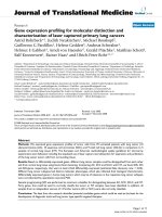
we found several spherical or oval holes in TEM images,
which had relatively uniform s izes ranging from 10
-6
to
10
-7
m (Figure 1a, b). Since the number concentration
of these holes was estimated to be 10
7
to 10
8
cm
-3
,
which was obviously greater than that observed on the
replica samples of pure water without aeration (as the
control, see Figure 1c), most of these holes were consid-
ered to be MNBs that originally existed in solutions.
This is supported by the facts that the number concen-
tration of MNBs estimated from TEM images corre-
sponded to the value expected from DLS measurements
Uchida et al. Nanoscale Research Letters 2011, 6:295
/>Page 2 of 9
(10
7
cm
-3
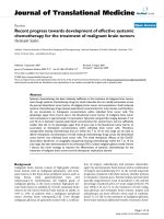
),andthatthesizedistributionsofMNBs
observed on the replica samples coincided qualitatively
with those obtained in the original bulk MNB water
[19] (Figure 2). The quantitative disagreement of the
two distributions observed in this figure could be caused
by that the size distribution from TEM images being
slightly modified because the present observations were
based on a limited amount of sample and observed
TEM images were random but in small numbers (here
n = 114). Therefore, we concluded that we could evaluate
the existence of O
2
MNBs formed in pure water by using
our freeze-fractured replica method. This conclusion also
(b)
(a)
(c)
Figure 1 Various TEM images of freeze-frac tured replica of pure O
2
MNBs in pure water. Spherical or oval NBs of (a) 500 nm in diameter
or (b) 200 nm in diameter were located in ice crystallites (smooth surface) or on their grain boundaries. (c) The replica sample of pure water
without aeration was shown as a control. Each scale bar indicates 500 nm.
Uchida et al. Nanoscale Research Letters 2011, 6:295
/>Page 3 of 9
supports the validity of the replica method for application
to MNB studies as mentioned previously [16,-18] and
indicat es that the lifetime of MNBs formed in pure water
was long enough to prepare the samples with quenching.
In order to examine the interaction between MNBs
and additi ves in the solution, we observed a dilute NaCl
solution containing O
2
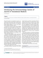
MNBs. The obvious difference in
TEM images of these samples from those in pure MNB
water was that fine particles (less than 100 nm in dia-
meter) were observed on the grain boundary of ice crys-
tallites (Figure 3a). These fine particles were also
observed in the control (no MNB sample, Figure 3b).
MNBs were also simultaneously trapped on the grain
boundary in this figure. Based on the analogous features
of disaccharide solutions [20,21], the ice crystallites were
formed during the sample quenching process, and t he
fine particles were the agglomeration of condensed salts
dissolved in the original solution due to the freeze-
condensation mechanism. The remaining area in the
grain boundary is considered to be the glass state of the
solution. The shape and size o f MNBs in 1% NaCl solu-
tion seemed to be similar to those in pure water. Its
number concentration was slightly lower than that in
pure water system, which may have resulted from the
sample being prepared more than 1 week after aeration.
This result is qual itatively consistent with the DLS
measurements in pure water [19]. The addition of a small
amount of NaCl is expected to play a positive role o f
stabilizing MNBs in engineering applications. However,
we could not find obvious characteristics in our T EM
images as reported for the sample with surfactants [17].
Since there are conflicting claims for the effect of ionic
solutions on MNB stabilities [22], further systematic
investigations are required for understanding the effect of
additives on the lifetime of MNBs.
The replica observations for the wastewater with
MNBs exhibited obviously different images from those
mentioned above. Several parts of the replica samples
prepared from the wastewater had a rough surface
including many fine particles (less than 10
-7
mindia-
meter) as depicted in Figure 4a, b. These fine particles
resulted from either invisible small particles or from the
agglome ration of the condensed soluble impuri ties such
as glucide or calcium sulfate, both of whi ch are consid -
ered to be included in the original wastewater. In addi-
tion, we sometimes found micron-sized ice crystallites
among the fine partic les, and found that they had crys-
talline facets with a smooth surface (center of Figures
4a, b). These ice crystallites are considered to be formed
in the polluted solution during the sample quenching.
The remaining area around the fine particles is the
glassy body. The smooth surface of ice crystallite
suggested that the ob served rough surface surrounding
the ice did not come from any artifacts on the replica
during the sample preparation, such as frost dep osit.
The analogous features for disaccharide solutions [20]
suggested that the original solution included a relatively
high concentration of impurities because the crystallites
Relative number
concentration (a.u.)
Size
(
nm
)
Frequency in Intensity (%)
0
2
4
6
8
10
1 10 100 1000 10000
Relative number
concentration (a.u.)
Size
(
nm
)
Frequency in Intensity (%)
0
2
4
6
8
10
1 10 100 1000 10000
Relative number
concentration (a.u.)
Size
(
nm
)
Frequency in Intensity (%)
0
2
4
6
8
10
1 10 100 1000 10000
Figure 2 Comparison of size distributions of O
2
MNBs formed in pure water. The size distribution of MNBs obtained from TEM images of
replica samples prepared just after aeration (solid circles with arbitrary unit, n = 114) is similar to that measured by a dynamic light scattering
method (open diamonds with error bars and a smoothed line), which was reproduced from Ushikubo et al. [19].
Uchida et al. Nanoscale Research Letters 2011, 6:295
/>Page 4 of 9
were small and faceted, which indicated they grew
slowly due to the impurities.
In contrast, several replica images in the same
quenched sample exhibited a relatively wide smooth area
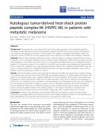
similar to that of the pure water sample. In that area, we
found some spherical objects that had adsorbed a large
number of fine particles on their surface (Figur e 5).
These spherical objects ranged from 5 to 9 × 10
-7
min
diameter, which corresponded to the expected size of
the MNBs formed in the solution. The fine particles
on the spherical objects (or NBs) were 2 to 3 × 10
-8
m
in diameter. Since no fine particles were observed
around the NB, we postulated that these fine particles
were impurities originally included in the wastewater
and located around the MNB. Therefore, Figure 5
clearly indicates that MNBs in the wastewater trapped
(b)
(a)
Figure 3 TEM images of freeze-fractured replica of 1% NaCl solution containing O
2
MNBs. Scale bar indicates 200 nm. (a) Precipitated fine
impurity particles (10 to 60 nm in diameter) and MNBs (200 and 300 nm in diameter) coexisted at the grain boundary of ice crystallites. Some
fine particles were located around small MNBs but did not cover the entire bubble surface. (b) Replica sample of 1% NaCl solution without
MNBs shown as a control.
Uchida et al. Nanoscale Research Letters 2011, 6:295
/>Page 5 of 9
impurities existed around them on their surfaces and
concentrated impurities during their residence time
until quenching. This is the first direct observation of
a typical property of MNBs, that is, MNBs adsorb
effectively and concentrate impurities in solutions on
their surface, which results in separating impurities
from solutions.
Compared to the fine particles observed in 1% NaCl
solutions (Figu re 3), the fine particles in the wastewat er
adsorbed on a MNB homogeneously . This may indi cate
Figure 4 Various TEM images of freeze-fractured replica of the wastewater containing MNBs. Each scale bar indicates 500 nm. An ice
crystallite with a faceted smooth surface was located in the center of each picture (a, b), and surrounded by a rough surface composed of fine
particles (impurities). The remaining area around the particles is the glass state of the solution.
Uchida et al. Nanoscale Research Letters 2011, 6:295
/>Page 6 of 9
Figure 5 Various TEM images of freeze-fractured replica of the wastewater containing O
2
MNBs. Each scale bar indicates 100 nm. (a, b)
The MNB (850 nm in diameter) located in the center of each picture adsorbed many fine particles (20 nm in diameter) on its surface. The
extended picture in (a) depicts the bubble-solution boundary indicating the process by which fine particles were attracted to the bubble
surface. In contrast, no fine particles were observed around the MNB. (c) MNBs that captured fine particles were also located on the grain
boundary between ice crystallites.
Uchida et al. Nanoscale Research Letters 2011, 6:295
/>Page 7 of 9
that the fine particles on MNBs in the wastewater were
not the precipitation of soluble i mpurities but t he inso-
luble s mall particles originally existing in the solution.
The homogeneous distribution of fine particles near the
MNB surface (within 50 nm from the interface, see the
extended figure of Figure 5a) seemed to suggest that
fine particles in the wastewater tended to be attr acted to
the MNB. Based on these TEM images of replica sam-
ples from the wastewater (Figures 4 and 5), the impurity
adsorption of MNBs in the wastewater can be described
as follows (Figure 6). If the wastewater including both
fine particles and soluble impurities at a relatively high
concentration were solely quenched at liquid nitrogen
temperature, fine particles could be fixed homoge-
neously i n the glass state of the solution, and some ice
crystallites would be formed by the freeze-condensed
mechanism ( Figure 6b, b’ ). Since the impurity concen-
tration was high, the ice crystallite nucleation was lim-
ited, and its growth was slow enough to form the
crystalline facets. T his result is related to the fact that
the area of the glass state with fine particles exceeded
that of the ice crystallites. However, if the solution
included MNBs, the insoluble particles would be col-
lected on the MNBs by the attractive force between
them in solutions (Figure 6c). The mobility of MNBs
was not so high and the attractive force would only be
present at limited distances, so the sweep area of a
MNB in the solution was limited to only around the
bubble (Figure 6a). Figure 5 depicts the quenched
features of this condition (Figure 6c’ ). Therefore, it is
conceivable that the application of MNBs to the engi-
neering aspects is effective, but its total effectiveness
would directl y depend on the number c oncentration of
MNBs and on their residence time.
Conclusions
We performed the TEM observation of the freeze-
fracture replica to investigate the morphological features
of MNBs in solutions. The MNBs in pure water were
spherical or oval, and their size distribution ranged from
10
-6
to 10
-7
m, which was close to those obtained by the
usual method for the MNB chara cterization (DLS mea-
surement). Similar MNB features were observed in the
TEM images of the 1% NaCl solution system, although
the interaction between MNBs and the precipitated
solute particles was not obvious. These results con-
firmed the feasibility of applying TEM o bservat ion with
the freeze-fracture replica method for investigating
MNBs in solutions.
When we applied this method to MNBs aerated in the
wastewater of a sewage plant, we observed the special
features of MNBs that collected surrounding impurities
on their surfaces. The detailed investigation of ob tained
TEM images of the same wastewater suggested that the
B
B
a)
b’)
c’)
In the solution
quenching
WW
c)
b)
In TEM images
magnified views
PW
I
B
PW
WW
WW
B
B
a)
b’)
c’)
In the solution
quenching
WW
c)
b)
In TEM images
magnified views
PW
II
B
PW
WW
WW
Figure 6 Illustrations of adsorption properties of MNBs in wastewater and of their quenching features. (a) The original wastewater (WW)
includes both impurities (small dots) and several amounts of MNBs (B). Since a MNB sweeps impurities around it on the surface, the swept area
is less polluted (white area around B) and the surface of the MNB is covered by impurities (small dots). When this solution is quenched and the
replica samples are prepared on area (b), no MNBs with homogeneously dispersed impurities were observed. We can observe the TEM image of
(b’) fine particles homogeneously dispersing with a small ice crystallite (I) formed in the quenching process (related to Figure 4). In contrast,
when the replica sample was prepared on area (c) including the MNB surrounded by purified water (PW), the observed TEM image was (c’) the
MNB adsorbing fine particles on its surface in smooth ice crystallites (related to Figure 5).
Uchida et al. Nanoscale Research Letters 2011, 6:295
/>Page 8 of 9
sweepareaofaMNBinthesolutionwaslimited.
Therefore, it is conceivable that the application of
MNBs to engineering aspects is effective, but its total
effectiveness would strongly depend on the number con-
centration of MNBs and on their lifetime.
Abbreviations
MBs: microbubbles; MNBs: micro- and nanobubbles; NBs: nanobubbles; TEM:
transmission electron microscope; DLS: dynamic light scattering.
Acknowledgements
A part of this study was financially supported by the Society for Techno-
innovation of Agriculture, Forestry and Fishers (the Green project), organized
by Dr. A. Iwamoto and Dr. K. Koide. TEM observat ions were financially
supported by the Hokkaido Innovation through Nano Technology Support
and technically supported by Dr. N. Sakaguchi and Dr. T. Shibayama
(Hokkaido Univ.). The replica sample preparations were technically supported
by Prof. K. Gohara and Dr. M. Nagayama (Hokkaido Univ.), and Dr. S.
Okutomi (JEOL Ltd.). DLS measurement data was partly provided by Ms. A.
Irie (Quantum Design Japan, Inc.) and I. Otsuka (Ohu Univ.).
Author details
1
Division of Applied Physics, Faculty of Engineering, Hokkaido University,
Sapporo 060-8628, Japan
2
Department of Biological and Environmental
Engineering, Graduate School of Agricultural and Life Sciences, The
University of Tokyo, Tokyo 113-8657, Japan
3
Department of Biological
Science, Faculty of Science and Engineering, Chuo University, Tokyo 112-
8551, Japan
4
Tsuno Rice Fine Chemicals Co., Ltd., Wakayama 649-7194, Japan
5
R&D Center, Mayekawa MFG. Co., Ltd., Ibaraki 302-0118, Japan
6
Mixing
Project, Nikuni Co., Ltd., Kanagawa 213-0032, Japan
Authors’ contributions
TU carried out TEM observations with sample preparations, and performed
the entire observation analysis. TU, SO, and MO conceived of the study and
participated in the experimental design and coordination. They also drafted
the manuscript. SO prepared MNBs in pure water and analyzed the particle
size distribution with DLS. TT, KS, SS, YT, and KM participated in the design
and construction of the sewage plant and performed the sample
preparation of MNBs in the wastewater. All authors read and approved the
final manuscript.
Competing interests
The authors declare that they have no competing interests.
Received: 17 December 2010 Accepted: 5 April 2011
Published: 5 April 2011
References
1. Takahashi M: ζ potential of microbubbles in aqueous solutions: electrical
properties of the gas-water interface. J Phys Chem B 2005,
190:21858-21864.
2. Najafi AS, Drelich J, Yeung A, Xu Z, Masliyah J: A novel method of
measuring electrophoretic mobility of gas bubbles. J Colloid Interface Sci
2007, 308:344-350.
3. Choung J, Luttell GH, Yoon RH: Characterization of operating parameters
in the cleaning zone of microbubble column flotation. Int J Mineral
Process 1993, 39:31-40.
4. Yoshida A, Takahashi O, Ishii Y, Sekimoto Y, Kurata Y: Water purification
using the adsorption characteristics of microbubbles. Jpn J Appl Phys
2008, 47:6574-6577.
5. Li P, Tsuge H: Water treatment by induced air flotation using
microbubbles. J Chem Eng Jpn 2006, 39:896-903.
6. Fan M, Tao D, Honaker R, Luo Z: Nanobubble generation and its
application in froth flotation (part I): nanobubble generation and its
effects on properties of microbubble and millimetre scale bubble
solutions. Mining Sci Technol 2010, 20 :1-19.
7. Wu Z, Chen H, Dong Y, Mao H, Sun J, Chen S, Craig VSJ, Hu J: Cleaning
using nanobubbles: defouling by electrochemical generation of bubbles.
J Colloid Interface Sci 2008, 328:10-14.
8. Liu G, Wu Z, Craig VSJ: Cleaning of protein-coated surfaces using
nanobubbles: an investigation using a quartz crystal microbalance. J
Phys Chem C 2008, 112:16748-16753.
9. Park J-S, Kurata K: Application of microbubbles to hydroponics solution
promotes lettuce growth. HortTechnology 2009, 19:212-215.
10. Ago K, Nagasawa K, Takita J, Itano R, Morii N, Matsuda K, Takahashi K:
Development of an aerobic cultivation system by using a mirobubble
aeration technology. J Chem Eng Jpn 2005, 38:757-762.
11. Li P, Tsuge H: Ozone transfer in a new gas-induced contactor with
microbubbles. J Chem Eng Jpn 2006, 39:1213-1220.
12. Fujikawa S, Zhang R, Hayama S, Peng G: The control of micro-air-bubble
generation by a rotational porous plate. Int J Multiphase Flow 2003,
29:1221-1236.
13. Tabei K, Haruyama S, Yamaguchi S, Shirai H, Takakusagi F: Study of micro
bubble generation by a swirl jet. J Env Eng 2007, 2:172-182.
14. Ljunggren S, Eriksson JC: The lifetime of a colloid-sized gas bubble in
water and the cause of the hydrophobic attraction. Colloids Surf A
Physicochem Eng Aspects 1997, 129-130
:151-155.
15. Habich A, Ducker W, Dunstan DE, Zhang X: Do stable nanobubbles exist
in mixtures of organic solvents and water? J Phys Chem B 2010,
114:6962-6967.
16. Switkes M, Ruberti JW: Rapid cryofixation/freeze fracture for the study of
nanobubbles at solid-liquid interfaces. Appl Phys Lett 2004, 48:4759-4761.
17. Dressaire E, Bee R, Lips A, Stone HA: Interfacial Polygonal Nanopatterning
of Stable Microbubbles. Science 2008, 320:1198-1201.
18. Ohgaki K, Khanh NQ, Joden Y, Tsuji A, Nakagawa T: Physicochemical
approach to nanobubble solutions. Chem Eng Sci 2010, 65:1296-1300.
19. Ushikubo FY, Furukawa T, Nagasawa R, Enari M, Makino Y, Kawagoe Y,
Shiina T, Oshita S: Evidence of the existence and the stability of nano-
bubbles in water. Colloids Surf A Physicochem Eng Aspects 2010, 361:31-37.
20. Uchida T, Nagayama M, Shibayama T, Gohara K: Morphological
investigations of disaccharide molecules for growth inhibition of ice
crystals. J Crystal Growth 2007, 299:125-135.
21. Uchida T, Takeya S: Powder X-ray diffraction observations of ice crystals
formed from disaccharide solutions. Phys Chem Chem Phys 2010,
12:15034-15039.
22. Hampton MA, Nguyen AV: Nanobubbles and the nanobubble bridging
capillary force. Adv Colloid Interface Sci 2010, 154:30-55.
doi:10.1186/1556-276X-6-295
Cite this article as: Uchida et al.: Transmission electron microscopic
observations of nanobubbles and their capture of impurities
in wastewater. Nanoscale Research Letters 2011 6:295.
Submit your manuscript to a
journal and benefi t from:
7 Convenient online submission
7 Rigorous peer review
7 Immediate publication on acceptance
7 Open access: articles freely available online
7 High visibility within the fi eld
7 Retaining the copyright to your article
Submit your next manuscript at 7 springeropen.com
Uchida et al. Nanoscale Research Letters 2011, 6:295
/>Page 9 of 9