Báo cáo hóa học: " Research Article Meta-Model and UML Profile for Requirements Management of Software and Embedded Systems" pot
Bạn đang xem bản rút gọn của tài liệu. Xem và tải ngay bản đầy đủ của tài liệu tại đây (1.77 MB, 14 trang )
Hindawi Publishing Corporation
EURASIP Journal on Embedded Systems
Volume 2011, Article ID 592168, 14 pages
doi:10.1155/2011/592168
Research Article
Meta-Model and UML Profile for Requirements Management of
Software and Embedded Systems
Tero Arpinen, Timo D. H
¨
am
¨
al
¨
ainen, and Mar ko H
¨
annik
¨
ainen
Department of Computer Systems, Tampere University of Technology, P.O. Box 553, 33101 Tampere, Finland
Correspondence should be addressed to Tero Arpinen, tero.arpinen@tut.fi
Received 18 August 2010; Revised 15 December 2010; Accepted 14 February 2011
Academic Editor: Jean-Pierre Talpin
Copyright © 2011 Tero Arpinen et al. This is an open access article distributed under the Creative Commons Attribution License,
which permits unrestricted use, distribution, and reproduction in any medium, provided the original work is properly cited.
Software and embedded system companies today encounter problems related to requirements management tool integration,
incorrect tool usage, and lack of traceability. This is due to utilized tools with no clear meta-model and semantics to communicate
requirements between different stakeholders. This paper presents a comprehensive meta-model for requirements management.
The focus is on software and embedded system domains. The goal is to define generic requirements management domain concepts
and abstract interfaces between requirements management and system development. This leads to a portable requirements
management meta-model which can be adapted with various system modeling languages. The created meta-model is prototyped
by translating it into a UML profile. The profile is imported into a UML tool which is used for rapid evaluation of meta-model
concepts in practice. The de veloped profile is associated with a proof of concept report generator tool that automatically produces
up-to-date documentation from the models in form of web pages. The profile is adopted to create an example model of embedded
system requirement specification which is built with the profile.
1. Introduction
Requirements Management is a crucial part of systems
development. Several solutions and tools for requirements
management process have been provided for software devel-
opment [1]. However, surveys have indicated problems in
requirements management processes used by practitioners
related to tool integr a tion, incorrect tool usage, and lack
of traceability of requirements to development artifacts [2].
The most common tools currently used for requirements
management in industry are word-processing packages,
spreadsheet applications, and internal web pages. Using
such tools with no clearly defined templates can lead to
errors in communicating requirements between different
stakeholders. As these errors are related to requirements
capture, the y happen early in the development process, and
thus, they are likely to incur high in cost in later development
phases.
Unified Modeling Language version 2 (UML2) [3]isa
standard language for modeling systems. UML2 offers a rich
set of diagr ams for software architecture modeling but also
expansion and tailoring methods for other domains. One of
such expansion methods is to use UML profiles that add new
domain-specific model elements to the UML language with
stereotypes, tag definitions, and constraints [4].
Meta-model (i.e., domain model) is a structure of con-
cepts in a certain domain. Meta-model captures abstrac tions
and relationships of the target domain concepts. Meta-
Object Facility (MOF) [5] is a standard language for creating
meta-models. It is a subset of the UML language.
This paper presents a comprehensive meta-model for
requirements management. The focus is on software and
embedded system domains. Our goal is to define generic
requirements management domain concepts and to establish
abstract interfaces between requirements management and
systems development. This leads to a portable requirements
management meta-model which can be used with various
system modeling languages. The meta-model also focuses
on temporal aspects of requirements management during
development process, such as states of requirements and
changing requirements. Hence, the goal is to capture the
whole requirements management process, not just the
concepts needed for requirements specification. The MOF
language is used for meta-model definition.
2 EURASIP Journal on Embedded Systems
Define
modeling
domain
Define MOF
metamodel
(domain model)
Create
UML profile
Addtoolsupport
(optional)
Create model with
the profile
Process the model
1
2
3
4
5
6
• Ideas in mind, blackboard, etc.
• Meta Object facility (MOF)
• Domain model is presented as UML
classes, attributes, operations and
associations.
• Metamodel elements are mapped
into UML model elements
• Existing UML metaclasses are
extended with stereotypes,
stereotype attributes, and constraints
• Model is created for certain domain
with the notation and semantics
defined by the profile
• Plugins tools and scripts for model
processing
• Customizing diagrams and model elements
• Removal of unnecessary features in UML
tool
• Define the key abstractions of the problem
and their relationships with each other
• Result is a domain model
• Present the modeling domain (key
abstractions) using a small set of UML
model elements
• Define which UML modeling elements are
used in modeling and how they can be used
• Defines the core of the developed modeling
language (diagrams types and notations)
•Makes the language portable between tools
• Enables designer-friendly front-end
(usability, speed, quality)
• Result is model and a set of views
(diagrams) to the model
• Design automation and model
transformations
• Create new models from existing models
• Change presentation format of the model
Domain concepts
for requirements
management
Requirements
management
UML meta-model
Requirements
management
profile
To o l
customization/
profile import
Example model
for embedded
application
HTML-report
generator
Process phase Representation of knowledge Purpose of the phase Outcome of this work
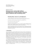
Figure 1: General phases for creating, deploying, and using a UML profile included with outcome of this work.
The created meta-model is prototyped by translating it
into a UML profile. The profile is imported into a UML tool
which is used for rapid evaluation of meta-model concepts
in practice. The UML tool is further customized to remove
unnecessary features from the tool to create a designer-
friendly interface. The primary purpose of the profile is to
prototype the meta-model, but it is also suitable to be used in
real requirements management as such. For this purpose, the
profile is associated with a proof of concept report generator
tool. Its task is to form web pages documenting the current
state of requirements. We illustrate how the profile is adopted
in practice with a case study of an embedded system design.
The work has been carried out in a joint project with several
embedded system companies that are defining a common
requirements management process and tool.
The paper is structured as follows. Section 2 presents
the approach for prototyping and evaluating requirements
management concepts. Related work on requirement man-
agement methods, meta-models, and UML profiles are
discussed in Section 3. The general requirements process
concepts are discussed in Section 4. Our meta-model for
requirements management is presented in Section 5.The
UML profile definition and tool customization is covered
in Section 6. The example model is presented in Section 7 .
The report generator tool is presented in Section 8 . Section 9
concludes the paper.
2. Our Approach for Prototyping Requirements
Management Meta-Model
Figure 1 presents the general phases for creating, deploying,
and using a UML profile. It also shows the outcome of this
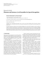
work regarding each phase. Figure 2 presents the concrete
flow used in this work.
There is a widely used de facto standard approach for
creating UML profiles proposed by Selic [6]. We follow this
approach of designing a UML profile built on conceptual
meta-model (domain model). The first phases are to discover
the key abstractions and relationships of the target domain
and to form a meta-model of the problem. The idea is
to identify the concepts that simplify the modeled reality
from aspects relevant to the particular domain. It should be
emphasized that the meta-model does not imply the model
notation when using the resulting UML profile. Instead, it
forms the abstract syntax of the profile.
Next, the concepts of the meta-model are translated
into a UML profile. This is done by creating stereotypes
from domain modeling concepts and then mapping the
stereotypes to UML meta-classes. The usage of stereotyped
model elements is refined with tag definitions (stereotype
attributes) and constraints. For example, a UML classifier
can be given stereotype Requirement which means that the
resulting model element behaves in diagrams as a classifier
EURASIP Journal on Embedded Systems 3
MagicDraw plugin interface
Model processing
Formalized
Domain concepts for
requirements
management (text)
Requirements
management UML
meta-model (MOF)
Requirements
management profile
(UML diagrams)
HTML-report generator
(Java)
Refined
HTML-report
(web-browser)
Profile import
Prototype modeling tool
(customized MagicDraw)
Requirements model
developed with the profile
Figure 2: Flow for defining, deploying, and using UML profile for
requirements management.
but also has the distinct properties of a requirement. Tag
definitions of the stereotype refine the properties of the new
model element. Constraints Constraining can be performed,
for example, with Object Constraint Language (OCL) [7].
It should be noted that not all concepts of the meta-
model necessarily become stereotypes. Only those concepts
should be covered that are necessary in practical modeling
situations. Moreover, as stereotypes are extending the UML
meta-model, new stereotype should not be created if the
corresponding concept is already covered by the UML
language.
The benefit of this kind of profile design approach is that
the features of the UML language do not bias the definition of
the domain-modeling problem. This is because the semantics
of the model become separated from the notation of the
model.
After creating a UML profile, additional tool customiza-
tioncanbecarriedouttoremoveunnecessaryfeatures
from the UML tool that are not needed for requirements
management purposes. We use MagicDraw UML 16.5 tool
from No Magic [8] as the UML tool. It allows creating
custom diagrams and to customize model elements using
aproprietaryDSL engine. In practice, this means that only
the model elements of the profile are visible for the modeler
while other UML-related elements are hidden from the tool.
This makes usage of the profile easier for designers.
After these phases, the deployed UML profile is ready to
be used in modeling. After creating the requirements specifi-
cation model, an automated report generation can be carried
out using a dedicated model processing tool. It produces up-
to-date documentation of the requirements and takes care of
managing different versions of requirements releases. Only
phases 5 and 6 are used in everyday requirements engineering
work.
2.1. On UML Profiling f or Prototyping a Meta-Model. It
must be emphasized that there are several other ways
of prototyping a meta-model as a tool. For example,
Eclipse Graphical Modeling Framework (GMF) [9]provides
a model-driven approach to generating graphical editors
in Eclipse from a meta-model. The meta-model can b e
also implemented directly as a dedicated software program
using a software programming language, such as Java. Our
requirements management meta-model can be, and has
been, implemented as a spreadsheet template in Microsoft
Excel application.
The benefit of UML profiling is the fast and easy
transformation of MOF meta-model into a deployable UML
profile. This is because UML is defined with MOF [6]. There-
fore, same UML tool can be used for defining them both.
Furthermore, UML is a widely-adopted standard modeling
language with extensive tool support. Yet, although UML
profiles allow the reuse of tooling infrastructure the meta-
model implementation may suffer from the limitations of the
UML language itself. Nevertheless, UML profiling enables a
cost-effective solution for prototyping a meta-model.
3. Related Work
Related work has various recommendations, meta-models,
and UML profiles for requirements management. In the
following, some of the closest to our work are examined.
3.1. Recommendations for Requirements Management Pro-
cess. The IEEE computer society’s Guide to the Software
Engineering Body of Knowledge gives recommendations
on requirements management for software systems [10]. It
defines the basic concepts and presents general guidelines
for requirements management. It gives a detailed descr iption
of the phases of iterative requirements management process.
Some of its core concepts are reused in this work. Other
references on general requirement management of software
systems include for example, [11, 12].Thereareseveralpro-
posals for proprietary requirements management templates
and processes, such as [13, 14].
3.2. Meta-Models and UML Profiles for Requirements Manage-
ment. Researchers have developed various meta-models and
taxonomies for requirements management, each focusing on
different aspects. Kabanda et al. [15] define a requirements
meta-model for software systems that incorporates social
features: users, policies, and culture. Firesmith [16] presents
a detailed taxonomy for security-related requirements, and
Glinz [17] focuses on nonfunctional requirements. Ramesh
and Jarke [18] present reference models for requirements
traceability based on focus groups and interviews conducted
in 26 software development organizations. The synthesized
4 EURASIP Journal on Embedded Systems
Requirements
management
Requirements
Requirements
analysis
Requirements
validation
Requirements
specification
Product testing and
verification
Verification
models
Design models
Product design and
implementation
Feedback loop: new and changing requirements
elicitation
Figure 3: Iterative requirements management process.
models were validated with several case studies and incorpo-
rated in a number of commercial traceability tools.
SysML [19] is a standard UML profile that, among other
things, defines model elements and a specialized diagram for
documenting requirements. Models created with SysML can
be also attached to other UML models that make it generic
in nature. Berenbach and Gall [20] present UML stereotype
extensions for integrating the modeling of functional and
nonfunctional requirements as well as hazards in use case
diagrams. Zhu and Gordon [21]proposeaUMLprofile
for modeling desig n decisions and an associated UML
profile for modeling nonfunctional requirements. Pardillo
et al. [22] present a meta-model and UML profile for
measurable requirements that connect goals, requirements,
and measures.
3.3. Summary of Related Work. The related work proposals
have been, in most cases, targeted for software systems.
Although requirements management process for software
systems can be equally well used in embedded system
development due to similar nature of development processes,
the related proposals lack following characteristics important
for both domains in practical requirements management:
(i) documenting and tracking the states of requirements
during the development process,
(ii) allocating and reusing requirements among product
families, products, product variants, and system
components (e.g., processors, busses, SW modules,
etc.),
(iii) establishing relationships to system modeling, analy-
sis, and verification.
The main contribution of this paper is the definition of a
meta-model and UML profile for requirements management
to be utilized in practical software and embedded system
development which, among other things, incorporates the
above-mentioned aspects.
4. Requirements Management Process
The core of our meta-model definition is based on the
general requirements management process [10]. In the
following, an introduction to the process phases is given.
The requirements management process is composed of
five main phases show n in Figure 3. Requirements e licitation
is the first phase of the process. It involves investigating
possible stakeholders and listing their main requirements
for the product. The discovery of stakeholders is also
called stakeholder analysis. As the result of the requirements
elicitation, all stakeholders and their main requirements
should be listed.
The second step is requirements analysis. The first task
of the analysis is to make sure that no requirements
are in conflict with each other. Conflicting requirements
usually or i ginate from different objectives and motivations
of different stakeholders, but can be also due to errors
in the elicitation phase. Conflict resolution is always a
compromise in which one or several requirements must
change. The second task of the analysis is to refine the
requirements and form hierarchies and other relationships
between requirements. For example, this can be translating
end user requirements to derived system requirements.The
third task is to allocate requirements to design components,
system models, and tests that wil l verify them.
The third step is requirements s pecification. This step is
creating or changing requirements documentation based on
the elicitation and analysis. The documentation can be in
form of electronic document or internal web pages of the
company, for example. The specification acts as the first
EURASIP Journal on Embedded Systems 5
and foremost vehicle in communicating requirements to
system developers who use it as the basis for design and
verification. For this reason, it is important that there is a
common understanding among all stakeholders about the
semantics of the specification. The best approach to foster
this understanding and reduce misinterpretations is to force
specification writers to utilize disciplined and well-defined
templates, meta-models when writing the requirements
document.
Thefourthstepisrequirements validation. The first
task of the validation is to make sure that the formed
requirements define the right system. That is to make
sure that requirements truly correspond to stakeholders’
intentions before resources are committed to development.
The second task of the validation is to make an assessment
whether the requirements are feasible. Traditional techniques
for validation include reviews of requirements documents
and building early system models and prototypes.
In embedded system domain, the requirement validation
is closely related to design-space exploration (DSE) [23].
DSE is optimizing the platform and mapping based on
measuring relevant system parameters (e.g., power, execu-
tion time, and area) of several single-design points by static
analysis or simulation. From requirements management
aspect, the per formance results of design-space exploration
iterations should be compared a gainst the set requirements
for early requirement validation.
The final step comes after the design and implementation
phase and it is requirements verification. Although it comes
after the development phase, it is an important part of
the requirement management process. The purpose is to
verify that the end product or development process meet
the given requirements. For this purpose, the requirements
specification can include additional verification plans and
models that refine how the requirement is supposed to be
verified.
5. Meta-Model for Requirements Management
This section presents our meta-model for requirements
management. The meta-model is depicted by the class
diagrams presented in Figures 4–7. In the following, each
element of the meta-model is discussed separately.
5.1. Requirements and Their Properties. Figure 4 presents the
main abstra ctions related to requirements. Requirement is a
property that must be exhibited by a product, some of its
part (e.g., subsystem, module), or its development process.
Requirement has description, identifier, version, type, state,
owner, and stakeholders as its attributes.
Description is a verbal expression of the requirement.
The description should be expressed unambiguously and,
if possible, quantitatively [10]. This concerns especially to
nonfunctional requirements.
Identifier is a unique fingerprint of a requirement. It is
used to separate a requirement from other requirements with
a unique character string. On the other hand, a requirement
may have several Versions. This is to track small changes
of requirements after their first definition. Type classifies
requirements to belong into certain category based on their
nature. The possible categories have been defined in Figure 4
as an enumeration attribute. If the type of the requirement
is Restriction, then its nature can be fur ther refined with
Restriction type.
State of a requirement is composed of four attributes that
characterize its present status in the requirements manage-
ment process. The first component is Conflict state.Itdefines
whether the requirement has been analysed and if it is in
conflict. Validation state defines whether the requirement has
been validated. Authorization state determines whether the
requirement is authorized for development. This attribute
represents the final approval for committing resources to
development in the context of a single requirement. The
requirement can also be rejected. This means that it will not
be considered in the development at all. Verification state
defines whether the requirement has been verified after the
development phase.
A requirement has also an owner and one or several
stakeholders. Owner is an actor (person or company) who
is responsible for the life span of the requirement. The
owner takes care that the requirement is carried along the
project and that the actions taken in the project comply with
fulfilling the requirement. Stakeholder is an actor for whom
the requirement is somehow meaningful. A stakeholder
always gains or loses something based on the result of
fulfilling the requirement.
Contracts are elements that bundle requirements to-
gether. A new contract typically brings new requirements to
the product or development process.
5.2. Requirements Relationships. The network of require-
ments relationships is typically very complex in system
design and the nature of the relationships may be ambiguous.
However, it is important that the dependencies between
requirements are identified and documented. This helps
in later stages of development if requirements need to
be changed. Changing a requirement may require that
several other related requirements need to be reanalysed.
Identification of the relationships helps to narrow down
the number of requirements that need to be considered in
requirement analysis due to a change in a requirement. We
define three basic relationships between requirements which
are composite, derive,andconflict. They are presented in
Figure 5. All the basic relationships can be further refined
with a free-form description to give additional semantics for
them.
The composite relationship is used to decompose a com-
plex requirement into several subrequirements. This allows
to form requirement hierarchies. For example, composition
can be used to divide responsibility of fulfilling a requirement
between several design teams. The parent requirement is
fulfilled after all its child requirements are fulfilled. The
owner of requirement may change between hierarchy levels.
This is to allow division of responsibility. The stakeholders
are inherited from the upper levels of hierarchy to the lower
ones while allowing to add new stakeholders to lower levels.
The derive relationship can be used to express derivation
6 EURASIP Journal on Embedded Systems
≪enumeration≫
≪
enumeration≫
≪
enumeration≫
≪
enumeration≫
≪
enumeration≫
StakeHolderType
Acquirer
Developer
Customer external
Customer internal
End user
Other
Actor
AuthorizationState
Authorized
Rejected
Waiting
ValidationState
Not validated
Validated
Waiting
ValidityParameter
+description
+measurementTechnique
Actor
Person Company
is
is
Stakeholder
+description
Owner
+description
Authorization
+date
+authorizator: Person [*]
Validation
ConflictState
Conflict free
In conflict
Waiting
VerificationState
Verified
Not verified
Waiting
+state
1
∗
Requirement
+description [1]
+version [1]
+validityDate [1]
+identifier [1]
1
1
1
1
1
+state
1
1
1
1
0 1
∗
∗
Functional
Nonfunctional
Domain-specific
Product support
Restriction
Project
RequirementType
RestrictionType
None
Product
Company policy
To o l
Regulation
+description
+term [
∗
]
+party: Actor [
∗
]
Contract
≪enumeration≫
≪
enumeration≫
Figure 4: Main view of the requirements management meta-model.
dependencies between requirements. Derived requirements
need to be reanalysed when the source requirement changes.
Good example is a channel throughput requirement that is
analysed to derive requirements for, data bus width in bits,
data compression ratio, and max bit error rate (BER). The
conflict relationship indicates that two or more requirements
are in conflict which needs to be resolved before committing
resources to development.
There is usually other information related to a require-
ment in addition to its textual description. We define three
types of additional information. There are system models
that refine the requirement describing how the requirement
should be considered in the system. For example, a UML
sequence diagram can be used to describe the protocol
that refines the requirement “User must authenticate during
login prior to usage of the service”. In embedded system
domain, the system models can be built using for example
the standard profile for Modeling and Analysis of Real-Time
Embedded system (MARTE) [24], profile for Schedulability,
Performance and Time (SPT) [25], or some proprietary
profile such as the TUT-Profile [26].
Verifi cat ion models also refine requirements. They are
blueprints of test benches which are used to verify that the
particular requirement is met in the final implementation.
Documentation is all other external documentation that is
desired to be attached along with the requirement definition.
For example, a processor data sheet can be attached to a
requirement that restricts the underlying platform to utilize
the particular processor core as its foundation. These abstract
concepts and relationships allow attaching requirements and
EURASIP Journal on Embedded Systems 7
Requirement Requirement
Derive
+description
Composite +subreq
Derive +derived
Conflict
Conflict
+description
Refine
Refine
Refine
Dependency
Visibility
Interface
External
Internal
Allocated
Allocated
Verify
SystemModel
VerificationModel
Documentation
+ link
+ description
SystemParameter
+description
+unit of measurement
+equation
+estimated value
+realized value
DesignPart
Test
+owner: Actor
+description
+test objectives
+test methods
+technical details
+instance
Relation
ParameterCategory
Nonfunctional
Functional
Exterior feature
Standard
Project related
Parameter visibility
Customer
Development
Relation
+description
TestEvent
+description
+tester: Actor
+deadline date
+testing date
+test report
Direction
Increases
Decreases
Intensity
Additive
Linear
Polynomial
Exponential
TestResult
Passed
Failed
Pending
0 1 0 1
∗
∗
∗
∗
∗
∗∗
∗∗
∗∗∗
∗
∗
∗
∗∗
∗
1
1
1
1
1
1
1
Active
Completed
Planning
+description
≪enumeration≫
ChangeSetState
ChangeSet
≪enumeration≫
≪
enumeration≫
≪
enumeration≫
≪
enumeration≫
≪
enumeration≫
≪
enumeration≫
Figure 5: Requirement management meta-model relationships, system parameters, and tests.
system models without binding to any specific modeling
language.
5.3. Requirements and System Parameters. System parameter
is a concept that models some feature or quantity of a
product (e.g., power consumption, area, performance, etc.).
A requirement then determines the possible values (or value
boundaries) for such quantity.
Parameters help requirements engineers to piece together
the relationships between requirements. In requirement
elicitation, identifying system parameters and investigating
their relationships is an efficient way of defining new relevant
requirements.
System parameters are analysed to make early design
decisions and validate requirements. As a result of the
analysis, requirements are modified if it is observed that
current requirements are not feasible to implement as such.
In the final system, there will be some realized values for
the defined parameters that are verified by measurements or
some other observations.
A useful property for a requirement management tool
is the capability to define such system parameters, their
associations to requirements, and carry out at least simple
calculations with them. More demanding analysis must be
naturally separated to external analysis tools.
The system parameters have the following attributes in
the meta-model.
(i) Freeform description of the parameter.
(ii) Unit of measurement (e.g., watt, meter, kilogram,
etc.) in case the parameter is quantifiable.
(iii) Equations describing parameter’s relations to other
system parameters.
(iv) Estimated value is a value assigned for analysis. It can
be based on engineer’s best guess, previous knowl-
edge, datasheets, or measurements from prototype.
(v) Realized value is the actual value of the parameter
in the implementation. This value is compared to
requirements in the verification phase.
(vi) Visibility, that is, whether the property is a user
parameter or system parameter. User parameter is
a feature that is visible to product user (external
property) and system parameter is an internal prop-
erty shown only for the developer. Typically user
properties (and requirements) are used to derive
system properties (and requirements).
(vii) Relation defines association to other system param-
eter. It is a directed relationship that indicates how
8 EURASIP Journal on Embedded Systems
increasing the value of a parameter affects the other
parameter. It can either increase or decrease it.
The intensity can be additive, linear, polynomial, or
exponential.
5.4. Allocating Requirements to Design Hierarchy. In a typical
software and embedded system development, the require-
ments are refined and they become closer to actual design
components when information in the project is increased.
Various design decisions during the project lead into decom-
position of the system into smaller and smaller components
and modules that have their own specific requirements. This
creates an evident need to allocate requirements to certain
components in a design hierarchy.
For this purpose, the meta-model defines an abstraction
called design part. Design parts can be hierarchical and
requirements can be allocated to them. A requirement can
have one of the three visibilities from the point of view
of a design part: internal, external, and interface. Internal
means that requirement is implementation-dependent and
comes from the inside of the design part development. This
is also called a white box requirement. External requirement
comes from the outside. This is a requirement that the
environment of the design part requires. This is also called
a black box requirement. Interface requirement concerns the
interface of the design part. This involves how the design part
communicates with its surrounding environment and other
design parts. It should be noted that a single requirement can
be external for one design part and at the same time internal
for another.
5.5. Requirements and Verification. Verification is closely
related to requirements management. Tests are the main
vehicle for verifying requirements. We prefer that tests are
tracked together with requirements, but they should be
separated to different logical trees. These trees are then linked
together with relationships. There may be several tests for
one requirement and one test can be a part of verifying
several requirements. Tests have the foll owing attributes.
(i) Description: a free-form description of the test.
(ii) Owner: actor responsible of the test in the test tree.
This role is not necessarily responsible of conducting
the actual test event but definition and change of it
during product development (similar to requirement
owner).
(iii) Test objectives: clearly stated objectives for the test.
Which requirements and which aspects of them the
test is verifying.
(iv) Test methods: description of the methods that are
used in testing. This includes describing the test
process phases, used measurement techniques and
tools.
(v) Technical details: defines notes and possible restric-
tions of the used testing methods.
One test can have several test events. These are instances
of test and they must be planned and recorded during the
Requirement
Cost
Risk
+description
enumeration
PriorityLevel
Mandatory
Nice-to-have
High
Moderate
Low
1
0 1
0 1
∗
enumeration
RiskLevel
Figure 6: Requirement management meta-model interface to
project management.
product development. The attributes of a test event are as
follows.
(i) Description: short description of the test event.
(ii) Tester: actor responsible for conducting the test.
(iii) Deadline date: date when the test must be (or should
have been) taken place.
(iv) Testing date: actual testing date or planned testing
date.
(v) Test report: external documentation that reports the
testing event process and results of the test event.
(vi) Test result: according to test event, the test can be
passed, failed or pending.
5.6. Change Management and Change Sets. Change set is
a temporal concept in requirements management process
which contains a set of requirements needed to be changed
for some common reason. The purpose of the change sets
is to allow controlled change in requirements and allow
tracking the changes later on by associating them to some
specific goal.
Change set description defines the purpose of the changes
to be made for the selected set of requirements. Change set
state defines whether the change set is act ive, completed, or
in planning state. In active state, the changes are currently
being made for the defined set of requirements. The change
sets in completed states should be archived for traceability of
changes later on. Sets in planning states are yet to be made
and thus still inactive.
There may be several change sets active at the same time,
but careful consideration has to be carried out when two or
more active change sets contain overlapping requirements.
It is preferred that these kinds of overlapping change sets
should be prohibited completely to avoid uncontrolled
corruption of the requirements tree due to simultaneous
change of same requirements for different goals in mind.
5.7. D evelopment Process Related Abstractions. There are
three fundamental abstractions that are related to require-
ments management but which are somewhat always depen-
dent on the development process and project management.
Their metrics may differ according to policies used by the
organization. In the following, we provide examples of these
possible metrics. They are presented in Figure 6.
EURASIP Journal on Embedded Systems 9
Requirement
RequirementInstance
Product
ProductVariant
ProductFamily
ProductConfiguration
SystemParameter
+description
+unit of measurement
+equation
+estimated value
+realized value
∗
∗
∗
∗
∗
∗
∗
∗
∗
+snapshot
Figure 7: Products, product families, variants, and configurations.
Risk describes the possibility of the requirement not
becoming fulfilled and estimated losses if the requirement
fails. The losses can be economical, time, and failure-
propagation to other requirements. Failure propagation
can be presented by composite and derive relationships of
requirements. If one of the child requirements fails, then the
parent fails as well. If a derived requirement fails, it directly
implies a failure in at least one of its source requirements.
Priority is a property of a requirement that character-
izes its importance in the development. The priorities of
requirements can be used as basis for setting priorities of
project tasks. On the other hand, priorities can make the
requirement analysis more complex as different stakeholders
demand different priorities. The most simple prioritization is
dividing requirements into mandatory and nice-to-have type
of requirements. Other possibility is to use an integer value
that represents the importance of the requirement in relation
to other requirement.
Cost is a value that it takes individually to fulfill a
requirement. Good quantities for characterizing cost are
additional money and time. It should be noted that some
requirements may have divided costs since two requirements
may always share the same investments and project tasks.
These are always development process-dependent and need
to be considered in requirement-by-requirement basis.
5.8. Product Families, Products, Variants, and Configurations.
The meta-model also considers the hierarchy of products
and their variants in product families. From requirements
management perspective, the idea is to identify and reuse the
requirements between products in product families as well as
between different product variants. The meta-model related
to this classification is presented in Figure 7. Product is the
basic item which is a result of the development effort that
satisfies customers’ needs. Product family is a set of different
products sharing certain common features. The definition of
product families is highly organization and domain specific.
For example, it can depend on similar design and production
techniques, common features, or common implementation
platform. Product variant is a par allel development path or
customization of a product. For instance, a color camera and
black-and-white camera can be tailored from the same basic
product components and requirements, but ultimately lead
to different variants. Product configuration is a combination
of a variant and its version.
6. UML Profile for Requirements Management
The evaluation of requirements m anagement concepts con-
tinues from specifying the meta-model to creating a UML
profile. Thereafter, profile importing and additional tool
customization is carried out. These phases are presented
separately in the following subsections.
6.1. Profile Definition. Figure 8 illustrates how the profile is
constructed with stereotype extensions. Only three stereo-
types are shown in the figure for simplicity. The stereotypes
and their attributes correspond to abstractions of the meta-
model presented in the previous section. Other stereotypes
are similarly derived.
In the figure, it is shown how Requirement stereotype
extends UML meta-class Classifier. Other model elements,
except relationships, are also extensions of a classifier. This
means that the stereotype can be applied to any UML
classifier element (class, use case, actor, etc.). The resulting
model element can be adopted in diagrams where the
concerned classifier is allowed. This increases the flexibility
of adopting the profile.
The requirement stereotype contains string type
attributes for description, version, ID, authorization date,
and cost. Thus, they can be typed by the modeler in
free-form textual notation. Authorizators and owners are
also stereotype attributes. They become selectable from
the list of all defined actors (companies and persons).
The enumeration attributes are attached to the stereotype
the same way as in the meta-model. In the figure, only
10 EURASIP Journal on Embedded Systems
metaclass
Dependency
stereotype
Derive
[Dependency]
stereotype
StakeHolder
[Dependency]
+description: String
Analysed
Not analysed
In conflict
1
+ analysation
state
metaclass
Classifier
stereotype
Requirement
[Classifier]
+description: String
+version: String
+id: String
+authorization date: String
+authorizator: Actor [
∗
]
+cost: String
+owner: Actor [
∗
]
+qualitative refinements: String [
∗
]
Analys ationState
enumeration
Figure 8: Example stereotype extensions for requirements management.
hideMetatype = true
typesForSource =
Person
Company
typesForTarget
= Requirement
hideMetatype
= true
typesForSource = Requirement
typesForTarget =
Requirement
Requirement
allowedRelationships
=
customizationTarget = Requirement
hideMetatype = true
customizationTarget
=≪≫ StakeHolder
customizationTarget
=≪≫ Derive
≪≫ Derive
≪≫ Satisfy
≪≫ StakeHolder
≪≫ Composite
≪≫ Conflict
≪≫ Refine
≪≫ Owner
≪Customization≫
≪
Customization≫
StakeHolder
≪Customization≫
Derive
≪Customization≫
≪
Customization≫
Figure 9: Example customizations for requirements management.
analysation state is shown for simplicity, other state-related
attributes are defined in a similar manner. For a designer,
these attributes are defined from a pull-down menu where
the value can be selected from a set of allowed values. This
forces the modeler to use only legal values and thus reduces
errors in model construction if compared to free-form
textual input. The icon shown in top right corner of the
stereotype box is the unique symbol used for requirements
in diagrams. Similarly, other stereotypes have their own
defined symbols.
Figure 8 also shows stereotype extensions for Derive and
Stakeholder relationships. Both extend the meta-class Depen-
dency. The stakeholders are exceptionally defined with special
relationship that is used to bind actors to requirements
instead of being directly defined as an attribute of a require-
ment (as in the case of owners). This allows better emphasis
in diagrams on how stakeholders request requirements. This
is reasonable, because stakeholders are inherited to lower
level requirements in the hierarchy, whereas owners and
authorizators can change arbitrarily between requirement
and its subrequirements. The stakeholder relationship has
also an attribute des cription, that is used to explain the
intentions of the stakeholder for the particular requirement.
This is another reason for using a special relationship. Other
relationship stereotypes are defined so that unidirectional
relationships extend UML dependency (stakeholder, derive,
refine), whereas bidirectional relationships extend UML
association (composite and conflict).
EURASIP Journal on Embedded Systems 11
Product
Product
Image manipulation on FPGA
Stakeholders
Company
Company A
Company
Company B
Company
Company C
Company
Company D
StakeholderGroup
Project consortium
StakeHolder
StakeholderGroup
Project consortium
Area requirements
Requirement
Total area
Requirement
Bus area
Requirement
1 Gbyte ethernet area
Requirement
Video generator area
Requirement
Picture manipulator area
Requirement
Status register area
Throughput requirements
Requirement
Minimum frame rate
Derive
DeriveDerive
Protocol requirements
Protocol sequence diagram
Requirement
Transfer protocol
RefineRefine
Application specification
Documentation
StakeholderGroup
Project consortium
StakeHolder
Requirement
Picture size
Requirement
Minimum bus troughput
StakeholderGroup
Project consortium
StakeHolder
Requirement
Minimum bus troughput
Figure 10: Requirements hierarchy and stakeholders of image manipulation application on FPGA.
6.2. Tool Customization. The customization for requirement
management is done with in-build DSL engine of the
MagicDraw tool. We use the fol lowing features of the engine
to tailor the modeling language and tool for requirements
management.
(i) Hiding standard UML properties from the model
elements. This enables the designer to focus on
modeling the domain concepts and hiding irrelevant
UML-related properties which are not needed.
(ii) Defining allowed relationships between model ele-
ments. This reduces errors in model building as the
tool prevents forming illegal relationships.
Figure 9 illustrates the customization of the stereotypes
shown in Figure 8. A similar kind of customization is
performed for the rest of the stereotypes. The customization
is performed by defining tagged values of the stereotype
Customization.Thisstereotypeistoolspecificanditisinter-
preted by the MagicDraw DSL engine. The customization
target attribute is used to define the elements the particular
customization is applied to. The requirement element is
customized so that only certain relationships for it are
allowed.
Further, the relationship elements are tailored by defining
which types of elements they can connect. This is defined
with types of source and types of target attributes. For exam-
ple, the stakeholder relationship can only connect a company
or person to a requirement, whereas derive relationship can
be only established between two requirements. The DSL
engine takes into a ccount these rules dur ing model building
by preventing forming il legal relationships.
Other approach for this type of constraining would be
to use a separate constraining language such as OCL. Such
approach would be more portable. However, for our proto-
typing purposes the tool-specific constraining is sufficient.
12 EURASIP Journal on Embedded Systems
7. Example Model
This section illustrates how the modeling is carried out
in practice with the profile. Our example is requirements
specification of image manipulation application on HW plat-
form synthesized onto FPGA. The purpose of the application
is to test the interoperability and data transmission capa-
bilities between HW components of the underlying FPGA
technology. The development of the HW architecture has
been divided between different companies, each responsible
of implementing one or several HW components for the
platform. The three main requirements for the prototype are
as follows.
(i) Correct functionality of the application, data trans-
mission sequence between HW entities.
(ii) End-to-end data transmission throughput.
(iii) Maximum resource consumption of the design on
FPGA (logic elements and memory bits).
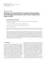
Figure 10 presents the main requirements model for the
system. It shows the three top-level requirements, their child
and derived requirements, and stakeholders requesting them.
All stakeholder companies form a stakeholder group named
project consortium using composition. The stakeholder group
is a convenient concept to bind companies and persons
together as stakeholders. It makes it easier to handle large
groups of stakeholders. The stakeholder group is attached to
all top-level requirements with the stakeholder relationship.
The total area requirement of the design is driven by
the maximum capacit y of the target FPGA. It is divided
into maximum number of logic elements, on-chip memory
bits, and DSP blocks (on-chip multipliers). The total area
requirement is divided into five subrequirements according
to decomposition of the design to IP components. Thus,
each IP component has its own requirement for area.
These requirements are balanced so that the total area
requirement is met if all IP area requirements are met. This
follows the definition of a hierarchical requirement. Each
subrequirement has its own owner, which in this case is the
same as the actor responsible designing the particular IP.
The minimum throughput requirement is informed
in Mbits/second. It has the underlying on-chip network
throughput as its subrequirement. The minimum through-
put is a derived requirement from the picture size and
minimum frame rate requirements.
The overall functionality requirement defines the pro-
tocol between IP blocks in the system and their combined
functionality. This requirement is refined by a UML sequence
diagram that shows the control and data transfers between
IP blocks in the active mode of the system. In addition, the
requirement is further refined by the functional specification
of the system represented in the model as external documen-
tation.
Figure 11 shows the customized menu for specifying
the properties of a requirement. In this case, it is shown
for the total area requirement. Normally, this specification
menu has UML-related properties of model element but due
to customization of the tool, only domain-related concepts
Figure 11: Requirement property dialog (customized MagicDraw
menu).
are visible for the modeler. The properties are the same
as defined in the meta-model and profile for requirements
management.
8. Report Generator Tool
The developed profile has been associated w ith a report
generator tool implemented as a MagicDraw plug-in in
Java programming language. Together the profile and the
report generator tool form the meta-model prototyping
environment. The report generator plug-in is used to process
the created model developed with the profile and automat-
ically create a documentation for the requirements. When
the states of the requirements change, new requirements
appear, or existing ones change, the report generator is
executed to form a new version of the documentation while
maintaining the version history for a single product. By this
way, the requirements model in MagicDraw can be freely
modified and the new versions of the reports are produced as
releases.
Figure 12 shows the main page of a generated report.
It lists the requirements of our example application, their
version, priority, and states. The state information indicates
that none of the requirements have been verified so far except
the communication bus area-related requirements. They are
fixed and already conformed to meet the given requirements
in the target technology. In addition to the previous ones,
total area, transfer protocol, and minimum frame r ate
have been authorized to development. Several requirements,
except most of component area-related requirements, have
been analysed, and no conflicts have been detected between
them. All requirements have been validated.
EURASIP Journal on Embedded Systems 13
Figure 12: Main view of generated requirements report.
The requirements report can be browsed using hyper-
links in the sidebar. Product Info page shows general
information on the product. Version history page allows the
user to examine the requirements version history and enter
any of the versions in the past. Requirement information
can be examined in different tables according to their
category as well as in from of graphs. Stakeholders and
their information can be also accessed individually. The
stakeholder graph shows how stakeholders are dependent on
different requirements.
9. Conclusions and Future Work
In this paper, we have presented a meta-model and UML
profile for requirements management of software and
embedded systems. We have shown well-defined reasons
behind the meta-model concepts and imported the UML
profile in general-purpose UML tool. The meta-model
covers several important aspects of requirements necessary
in practical systems development. These include temporal
aspectsofrequirementsaswellasinterfacestosystem
modeling, analysis, and verification. The future work consists
of utilizing the meta-model and profile in larger embedded
system development projects. Currently, we are adopting the
meta-model concepts to capture requirements of an electric
car motor controller unit [27].
References
[1] INCOSE Tools Database Working Group (DBWG), “Require-
ments Management Tools Survey,” 2010, ose
.org/ProductsPubs/products/rmsurvey.aspx.
[2]N.Juristo,A.M.Moreno,andA.Silva,“IstheEuropean
industry moving toward solving requirements engineering
problems?” IEEE Software, vol. 19, no. 6, pp. 70–77, 2002.
[3] Object Management Group (OMG), “OMG Unified Modeling
Language (OMG UML) Superstructure,” V2.1.2, November
2007.
[4] L. Fuentes-Fernndez and A. Vallecillo-Moreno, “An introduc-
tion to UML profiles,” European Journal for the Informatics
Professional, vol. 5, no. 2, pp. 5–13, 2004.
[5] Object Management Group (OMG), “Meta Object Facility
MOF Core Specification Version 2.0,” January 2006.
[6] B. Selic, “A systematic approach to domain-specific language
design using UML,” in Proceedings of the 10th IEEE Interna-
tional Symposium on Obj ect and Component-Oriented Real-
Time Distributed Computing, pp. 2–9, 2007.
[7] Object Management Group (OMG), “Object Constraint Lan-
guage Version 2.0 Specification,” May 2006.
14 EURASIP Journal on Embedded Systems
[8] No Magic Inc., “MagicDraw User’s Manual version 16.5,”
2009.
[9] Eclipse Foundation, “Eclipse Graphical Modeling Project
(GMP),” 2010, />[10] A. Abran, J. W. Moore, P. Bourque, R. Dupuis, and L. L.
Trip p, Guide to the Software Engineering Body of Knowledge,
(SWEBOK), IEEE, 2004.
[11] K. Eugene Wiegers, “Software Requirements,” Microsoft Press,
2003.
[12] G. Kotonya and I. Sommerville, “Requirements Engineering:
Processes and Techniques,” 2000.
[13] S. Robertson and J. Robertson, “Volere Requirements Tech-
niques: An Overview,” June 2008.
[14] P. Carlshamre and B. Regnell, “Requirements lifecycle man-
agement and release planning in Market-Driven requirements
engineering processes,” in Proceedings of the International
Workshop on Database and Expert Systems Applications,pp.
961–965, 2000.
[15] S. K. Kabanda, M. Adigun, and T. Chani, “A requirements
metamodel framework for enhancing product adoption,” in
Proceedings of the South African Te lecommunications Networks
and Applications Conference, 2007.
[16] D. G. Firesmith, “A taxonomy of security-related require-
ments,” in Proceedings of the International Workshop on High
Assurance Systems, 2005.
[17] M. Glinz, “On non-functional requirements,” in Proceedings of
the 15th IEEE International Requirements Engineering Confer-
ence (RE ’07), pp. 21–28, October 2007.
[18] B. Ramesh and M . Jarke, “To ward re ference models for
requirements traceability,” IEEE Transactions on Software
Engineering, vol. 27, no. 1, pp. 58–93, 2001.
[19] Object Management Group (OMG), “OMG Systems Model-
ing Language (SysML) Specification,” September 2007.
[20] B. Berenbach and M. Gall, “Toward a unified model for
requirements engineering,” in Proceedings of the IEEE Interna-
tional Conference on Global Software Engineering (ICGSE ’06),
pp. 237–238, October 2006.
[21] L. Zhu and I. Gorton, “UML profiles for design decisions and
non-functional requirements,” in Proceedings of the Workshop
on SHAring and Reusing Architectural Knowledge Architecture,
Rationale, and Design Intent, May 2007.
[22] J. Pardillo, F. Molina, C. Cachero, and A. Toval, “A UML profile
for modelling measurable requirements,” in Proceedings of the
Advances in Conceptual Modeling Challenges and Opportuni-
ties, Lecture Notes in Computer Science, pp. 123–132, 2008.
[23] M. Gr ies, “Methods for evaluating and covering the design
space during early design development,” Integration, the VLSI
Journal, vol. 38, no. 2, pp. 131–183, 2004.
[24] Object Management Group, “UML Profile for MARTE: Mod-
eling and Analysis of Real-Time Embedded Systems,” Version
1.0, November 2009.
[25] Object Management Group (OMG), “UML Profile for
Schedulability, Performance, and Time Specification (Version
1.1),” Januar y 2005.
[26] P. Kukkala, J. Riihim
¨
aki, M. H
¨
annik
¨
ainen, T. D. H
¨
am
¨
al
¨
ainen,
and K. Kronl
¨
of, “UML 2.0 profile for embedded system
design,” in Proceedings of the Design, Automation and Test in
Europe (DATE ’05), pp. 710–715, March 2005.
[27] eCars - Now!, 2010, koautot.fi/eng.