Advances in Lasers and Electro Optics Part 6 docx
Bạn đang xem bản rút gọn của tài liệu. Xem và tải ngay bản đầy đủ của tài liệu tại đây (3.13 MB, 50 trang )
Stimulated Brillouin Scattering Phase Conjugate Mirror and its Application to Coherent Beam Combined
Laser System Producing a High Energy, High Power, High Beam Quality, and High Repetition Rate Output
237
Fig. 7. Change of the beam pointing due to the tilting PBS: (a) gives no change in cross-type
amplifier with symmetric SBS-PCMs; (b) gives tilting in the conventional application of SBS-
PCM; (c) gives displacement in the combination of conventional mirror and SBS-PCM
2
22
11
22
1
(cos sin ) ( )
1
0
2
()
r
r
i
i
x
ii
y
E
iee
i
QRGR RGR
E
ee
θ
θ
φ
φ
φφ
θθ
−−
⎡⎤
⎡
⎤
⎡⎤
−−
==−
⎢⎥
⎢
⎥
⎢⎥
+
⎣⎦
⎣
⎦
⎣⎦
. (2)
In the setup of Fig. 8(b), the output polarization is represented by
22 2
11
22
1
8sin cos ( ) (cos sin )
1
0
2
()()cos4
rr
rr
iiii
x
ii
ii
y
E
ee e e
i
RGR Q QRGR
E
ee ee
θθ
θθ
φφϕφ
φφ
φφ
θθ θ θ
θ
−−
⎡⎤
⎡
⎤
⎡⎤
−+
==−
⎢⎥
⎢
⎥
⎢⎥
−+ + −
⎣⎦
⎣
⎦
⎣⎦
. (3)
In the setup of Fig. 8(c), the output polarization is represented by
2
2
11
22
22
1
cos 2 ( )
1
0
2
()()sin2
r
rr
i
i
x
ii
ii
y
E
ee
i
FRGR RGR F
E
ee ee
θ
θθ
φ
φ
φφ
φφ
θ
θ
−−
⎡⎤
⎡
⎤
⎡⎤
−
==−
⎢⎥
⎢
⎥
⎢⎥
−+ + −
⎣⎦
⎣
⎦
⎣⎦
. (4)
In the set up of Fig. 8(d), the output polarization is represented by
()
11
10
12
01
r
x
i
y
E
RGR F FRGR e
E
θ
φφ
+
−−
⎡⎤
⎡
⎤⎡⎤
==−
⎢⎥
⎢
⎥⎢⎥
⎣
⎦⎣⎦
⎣⎦
. (5)
Advances in Lasers and Electro Optics
238
Eq. (5) shows that the setup of Fig. 8(d) gives a perfect 90° rotated output and compensates
the TIB.
Fig. 8. Four possible optical schemes for rotating the polarization of the backward beam by
90-degree with respect to the input beam (L, lense; QWP, quarter-wave plate; FR, Faraday
rotator; AMP, amplifier)
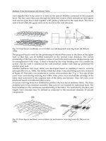
Fig. 9. Experimental results of the depolarization measurement for the four possible optical
schemes: (a) leak beam patterns, (b) depolarization ratio versus electrical input energy (Shin
et al., 2009)
Fig. 9(a) shows the corresponding leak beam patterns for the four possible optical schemes
of Fig. 8. This experimental result shows typical shape for each case. And Fig. 9(b) shows
the depolarization ratio versus electrical input energy. The experimental result for the setup
of Fig. 8(d) shows that the depolarization ratio is maintained at the low value as the
electrical input energy increases, while the results for other setups (Fig. 8(a) - Fig. 8(c))
shows the depolarization ratio rises as the electrical input energy increases (Fig. 9(b)).
5. Waveform preservation of SBS waves via prepulse injection
There are difficulties in a laser system with SBS, particularly when multiple SBS cells are
used in series for a high-power laser system. As the pulse is reflected from the SBS cell, the
temporal pulse shape is deformed so that the reflected SBS wave has a steep rising edge
(Shen, 2003). If SBS cells are used in series, the rising edge of the pulse becomes steeper and
can cause an optical breakdown in the optical components. For the SBS-PCM, the steep
Stimulated Brillouin Scattering Phase Conjugate Mirror and its Application to Coherent Beam Combined
Laser System Producing a High Energy, High Power, High Beam Quality, and High Repetition Rate Output
239
rising edge leads to low reflectivity and low fidelity of the phase conjugated wave in the SBS
medium (Dane et al., 1992). Thus, a suitable technique is needed to preserve the temporal
waveform of the reflected SBS wave (Kong et al., 2005d).
(a) (b)
Fig. 10. (a) Proposed system for preserving a temporal SBS pulse shape; (b) experimental
setup for this experiment: O, Nd3+:YAG laser oscillator; P, linear polarizer; HWPs, half-
wave plates; PBSs, polarizing beam splitters; ISO, Faraday isolator; FR, Faraday rotator;
QWPs, quarter-wave plates; PC, Pockels cell; Ms, full mirrors; W, wedge; L, convex lens
(f=15 cm); PDs, photodiodes; SBS cell (FC-75, 30 cm long).
The loss of the front part of the pumping energy to create the acoustic Brillouin grating is
one of the main causes of the deformation. As a solution, the prepulse technique can be used
to maintain the temporal waveform. In this scheme, the incident wave is divided into two
pulses, the prepulse and the main pulse, and the prepulse is sent to the SBS medium before
the main pulse with some delay. When the prepulse is injected before the main pulse, the
main pulse can be reflected by means of a preexisting acoustic grating and the reflected
pulse waveform can be preserved.
The scheme of the proposed setup for the temporal waveform preservation is presented in
Fig. 10(a). A single longitudinal mode Nd:YAG laser oscillator is used as a pump source. It
has a pulse width of 7~8ns and a repetition rate of 10 Hz. A Pockels cell (PC) is used to
adjust the proper ratio of the prepulse energy and the main pulse energy, and the
adjustment is made by adapting the high voltage that is applied to a PC for 10 ns, which is
the time it takes for an incoming pulse to pass through the PC. The PC is in the off state
when the pulse returns. The incident wave is split into two paths after PBS3, namely path 1
(prepulse) and path 2 (main pulse). The prepulse, which is initially s polarized, is reflected
when it reaches PBS2 after the SBS process because the PC is in the off state when the pulse
returns. The main pulse, which initially has p polarization, follows a process that is very
similar to the process of the prepulse and consequently has the p polarization needed to
pass through PBS2. There is another variation that uses no active optics. In Fig. 10(b), HWP2
and the Faraday rotator (45° rotator) are used instead of the PC in Fig. 10(a). HWP2 is used
to adjust the ratio of the prepulse energy and the main pulse energy. The measurement is
taken on path 2. A wedge plate is inserted to monitor the shape of the reflected main pulse
Advances in Lasers and Electro Optics
240
and the incoming main pulse waveform and the reflected SBS waveform are obtained. The
delay is modulated by the movable mirror, and the FC-75 fluid is used as the SBS medium.
Fig. 11. Incident and reflected waveforms with the prepulse injection; (a) E
pre
= 0 mJ, (b)
E
pre
= 2 mJ, (c) E
pre
= 2.5mJ, (d) E
pre
≥ 3mJ for values of T
delay
= 8 ns and E
main
= 10 mJ.
Let us define E
main
as the energy of the main pulse, E
pre
as the energy of the prepulse, and
T
delay
as the delay between the prepulse and the main pulse. Fig. 11 shows the waveform
measured for values of T
delay
= 8 ns and E
main
= 10 mJ. As E
pre
increases, the temporal
waveforms of the reflected wave become similar to that of the incident wave. When E
pre
exceeds 3 mJ, the experimental data have very similar aspects as the case of E
pre
= 3 mJ. This
similarity implies that if we set the prepulse energy equal to or larger than 3 mJ with a delay
of 8 ns, the main pulse need not consume its own energy to build the acoustic grating.
Fig. 12 shows the minimum prepulse energy required to preserve the waveform of reflected
pulse for various T
delay
(Yoon et al., 2009). For small T
delay
, the main pulse arrives so early
that a part of the main pulse energy can play a role in building the acoustic grating, because
the integrated energy of the prepulse is insufficient to generate the grating before the main
pulse arrives. Therefore the energy required to preserve the waveform of the main pulse is
higher than the moderate T
delay
. For large T
delay
, most of the acoustic grating disappears
before the main pulse arrives at the SBS interaction region so that more energy is required to
preserve the waveform.
A theoretical calculation that describes these experimental results was formulated using a
simple model. If the pump pulse is focused in the SBS medium, acoustic phonons are
generated and then accumulated in the focal area. Considering the phonon decay, the pump
pulse energy transferred to acoustic phonons and accumulated by time t, E
g
(t), is given by
(')/
0
() (') '
t
tt
g
Et Pte dt
τ
−−
=
∫
(6)
where P(t) is the temporal pulse shape and τ is the phonon lifetime. If the pulse width is
independent of the pulse energy, the temporal pulse shape can be represented as
() ()Pt EWt=⋅ (7)
where E is the pulse energy, and W(t) is the normalized waveform.
Stimulated Brillouin Scattering Phase Conjugate Mirror and its Application to Coherent Beam Combined
Laser System Producing a High Energy, High Power, High Beam Quality, and High Repetition Rate Output
241
To instigate the stimulated process, an amount of acoustic phonons over the required
threshold is required. The accumulated phonon energy needed for SBS ignition, called the
critical energy E
c
, can be determined by the maximally accumulated energy with a threshold
pump energy E
th
, as follows:
(')/
0
(') '
m
m
t
tt
cth
EEWte dt
τ
−−
=
∫
(8)
where t
m
is the time when E
c
becomes maximum. If the main pulse arrives at the interaction
region when E
g
(t) accumulated by the prepulse is larger than Ec, perfect waveform
preservation is achievable without energy consumption.
(')/
0
(') '
d
d
t
tt
cpre
E
EWte dt
τ
−−
≤
∫
(9)
where t
d
is the delay time between the prepulse and the main pulse. For theoretical
calculation, 2 mJ threshold energy and 0.9 ns phonon decay time were assumed (Yoshida et
al., 1997). Fig. 12 shows experimental results agree with the theoretical predictions
qualitatively.
Fig. 12. Minimum prepulse energy required to preserve the waveform of reflected pulse for
various T
delay
; comparison between the experimental results and the theoretical prediction
6. Coherent beam combined laser system with phase stabilized SBS-PCMs
To achieve a high repetition rate in a high-power laser, many researchers have widely
investigated several methods, such as a beam combination technique with SBS-PCMs, a
diode-pumped laser system with gas cooling, an electron beam–pumped gas laser, and a
large ceramic crystal (Lu et al., 2002; Kong et al., 1997, 2005a, 2005b; Rockwell & Giuliano,
1986; Loree et al., 1987; Moyer et al., 1988). The beam combination technique seems to be one
of the most practical of these techniques. The laser beam is first divided into several sub-
beams and then recombined after separate amplification. With this technique there is no
need for a large gain medium; hence, regardless of the output energy, this type of laser can
Advances in Lasers and Electro Optics
242
operate at a repetition rate exceeding 10 Hz and can be easily adapted to modern laser
technology. However, with conventional SBS-PCMs, the SBS waves have random initial
phases because they are generated by noises. For this reason, the phase locking of the SBS
wave is strongly required for the output of a coherent beam combination.
6.1 Phase control of the SBS wave by means of the self-generated density modulation
There have been several successful works in the history of the phase locking of SBS waves
(Rockwell & Giuliano, 1986; Loree et al., 1987; Moyer et al., 1988). Although these works
show good phase locking effects, they have some problems in terms of the practical
application of a multiple beam combination. In the overlapping method, all the beams are
focused on one common point. The energy scaling is therefore limited to avoid an optical
breakdown, and the optical alignment is also difficult. In the back-seeding beam method,
the phase conjugation is incomplete if the injected Stokes beam is not completely correlated.
Kong et al. (2005a, 2005b, 2005c) proposed a new phase control technique involving self-
generated density modulation. In this method, which is simply called the self-phase control
method, a simple optical composition is used with a single concave mirror behind the SBS
cell; furthermore, each beam phase can be independently and easily controlled without
destruction of the phase conjugation. Thus, the phase control method obviates the need for
any structural limitation on the energy scaling.
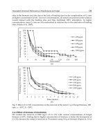
Fig. 13. Experimental setups of (a) wavefront division scheme and (b) amplitude division
scheme for phase control of the SBS wave by means of the self-generated density
modulation: M1,M2&M3, mirrors; W1,W2,W3&W4, wedges; L1&L2, cylindrical lenses:
L3,L4,L5&L6, focusing lenses, CM1,CM2,CM3&CM4, concave mirrors; H1&H2, half wave-
plates; PBS1&PBS2, polarizing beam splitters.
The wavefront division scheme, which spatially divides the beam, is used to demonstrate
the phase control effect with the self-phase control method in the first experiment (Kong et
al., 2005a, 2005b, 2005c). The experimental setup is shown schematically in Fig. 13(a). A
1064 nm Nd:YAG laser is used as a pump beam for the SBS generation. The pulse width is
7 ns to 8 ns, and the repetition rate is 10 Hz. The laser beam from the oscillator passes
through a 2
× cylindrical telescope and is divided into two parts by a prism, which has a high
reflection coating for an incident angle of 45°. The two parts of the divided beam pass
through separate wedges and are focused into SBS-PCMs. The wedges reflect part of the
Stimulated Brillouin Scattering Phase Conjugate Mirror and its Application to Coherent Beam Combined
Laser System Producing a High Energy, High Power, High Beam Quality, and High Repetition Rate Output
243
backward Stokes beams so that they are overlapped onto a CCD camera. Then, the
interference pattern of them is generated. The degree of the fluctuation of the relative phase
difference between the SBS waves is quantitatively analyzed by measuring the movement of
the peaks in the interference pattern.
For the case of the wavefront division, the divided sub-pump beams get fluctuating energies
for every shot due to the beam pointing effect of the laser source, which seems to generate
the fluctuation of the relative phase difference between the SBS waves, because the phase of
the SBS wave depends on the pump energy. This beam pointing problem can be overcome
by using an amplitude division method, whereby the sub-pump beams have almost the
same level of energy (Lee et al., 2005). The experimental setup of the amplitude division
scheme is shown in Fig. 13(b). In the amplitude division scheme, the laser beam from an
oscillator is divided into two sub-beams by a beam splitter (BS).
Fig. 14. Experimental result for the unlocked case: (a) schematic; (b) intensity profile of
horizontal lines selected from 160 interference patterns; (c) relative phase difference between
two beams for 160 laser pulses.
Fig. 14 shows the experimental schematic and experimental results for the unlocked case.
Each point in Fig. 14(c) represents one of 160 laser pulses. As expected,
δ has random value
for every laser pulse. Fig. 14(b) shows the intensity profile of the 160 horizontal lines
selected from each interference pattern. The profile also represents the random fluctuation.
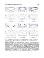
Fig 15 shows phase control experimental results in the wavefront division scheme. Fig. 15(a)
shows the schematic and the experimental result of the concentric-type self-phase control. A
small amount of the pump pulse is reflected by an uncoated concave mirror and then
injected into the SBS cell. The standard deviation of the measured relative phase difference
is ~ 0.165
λ. Moreover, 88% of the data points are contained within a range of ±0.25λ (±90°).
This result demonstrates that the self-generated density modulation can fix the phase of the
backward SBS wave. Fig. 15(b) shows the schematic and the experimental result of the
confocal-type self-phase control, where the pump beams are backward focused by a concave
mirror coated with high reflectivity. The standard deviation of the measured relative phase
difference is ~ 0.135
λ. Furthermore, 96% of the data points are contained in a range of
±0.25λ.
Advances in Lasers and Electro Optics
244
Fig. 15. Phase control experimental results in the wavefront division scheme, with (a)
concentric-type self-phase control ((left-up) schematic, (left-down) intensity profile of
horizontal lines from interference pattern, (right) relative phase difference between two
beams for 203 laser pulses) and (b) confocal-type self-phase control ((left-up) schematic,
(left-down) intensity profile of horizontal lines from interference pattern, (right) relative
phase difference between two beams for 238 laser pulses).
Fig. 16 shows phase control experimental results in the amplitude division scheme. Fig.
16(a) shows the schematic and the experimental result of the concentric-type self-phase
control. The standard deviation of the measured relative phase difference is ~ 0.0366
λ. And
Fig. 16(b) shows the schematic and the experimental result of the confocal-type self-phase
control. The standard deviation of the measured relative phase difference is ~ 0.0275
λ. By
employing the amplitude division scheme, the relative phase difference is remarkably
stabilized compared with the wavefront dividing scheme.
Stimulated Brillouin Scattering Phase Conjugate Mirror and its Application to Coherent Beam Combined
Laser System Producing a High Energy, High Power, High Beam Quality, and High Repetition Rate Output
245
Fig. 16. Phase control experimental result in the amplitude division scheme, with (a)
concentric-type self-phase control ((left-up) schematic, (left-down) intensity profile of
horizontal lines from interference pattern, (right) relative phase difference between two
beams for 256 laser pulses) and (b) confocal-type self-phase control ((left-up) schematic,
(left-down) intensity profile of horizontal lines from interference pattern, (right) relative
phase difference between two beams for 220 laser pulses).
6.2 Theoretical modeling on the phase control of SBS waves
In the previous section, the experimental results demonstrate the effect of the self-phase
control method. On the basis of the phase control experiments, we present in this section the
theoretical model suggested by Kong et al. to explain the principle of the self-phase control
(Ostermeyer et al., 2008). Given that the pump wave propagates towards the positive z
direction in the SBS medium, the pump wave, E
P
, and the Stokes wave, E
S
, can be expressed
as
)sin(
PPPP
zktAE
φ
ω
+−=
(10)
Advances in Lasers and Electro Optics
246
and
sin( )
ω
φ
=++
SSSS
EB tkz , (11)
where A and B are the amplitudes of E
P
and E
S
; ω, k and
φ
are the angular frequency, the
wave number and the initial phase, respectively; and P and S are the pump wave and the
Stokes wave, respectively. The density modulation of the SBS medium is proportional to the
total electrical field. The density modulation, ρ, can therefore be represented as
2
22 22
sin ( ) sin ( )
cos[( ) ( ) ( )]
cos[( ) ( ) ( )].
PS P P P S S S
PS PS PS
PS PS PS
EE A tkz B tkz
AB t k k z
AB t k k z
ρ
ω
φ
ω
φ
ωω φφ
ωω φφ
∝+ = −++ ++
−+−−++
+−−++−
(12)
Only the final term of Eq. (12) can contribute to the acoustic wave because the first two
terms are DC components and the third term denotes the fast oscillating components. The
acoustic wave can be also expressed as
0
cos( )
aa
tkz
ρρ φ
=Ω++
, (13)
where ρ
0
is the mean value of the medium density and Ω, k
a
, and
a
φ
are the frequency, the
wave number, and the initial phase of the acoustic wave, respectively. From Eqs. (12) and
(13), the relations of
P
S
ωω
Ω= − , =+
aPS
kkk and
aPS
φφφ
=− can be obtained. If
a
φ
and
P
φ
are known values,
S
φ
can be definitely determined in accordance with the phase relation.
If the acoustic wave is assumed to be initially generated at time t
0
and position z
0
, the
acoustic wave can be rewritten as
)]()(cos[
000
zzktt
a
−−−Ω=
ρ
ρ
]cos[
000
zktzkt
aa
+Ω−−Ω=
ρ
. (14)
The phase of the acoustic wave is then given by
00aa
tkz
φ
=−Ω +
. (15)
In conventional SBS generation, t
0
and z
0
have random values as the SBS wave is generated
from a thermal acoustic noise. However, t
0
and z
0
can be locked effectively by the proposed
self-phase control method.
Fig. 17. Concept of phase control of the SBS wave by the self-generated density modulation.
PM is a partial reflectance concave mirror whose reflectivity is r. E
P
and E
S
denote the pump
wave and the SBS wave, respectively.
Stimulated Brillouin Scattering Phase Conjugate Mirror and its Application to Coherent Beam Combined
Laser System Producing a High Energy, High Power, High Beam Quality, and High Repetition Rate Output
247
Fig. 17 describes the concept of the self-phase control method. The weak periodic density
modulation is generated at the focal point due to the electrostriction by an electromagnetic
standing wave that arises from the interference between the main beam, E
P
, and the low
intensity counter-propagating beam, rE
P
. In the suggested theoretical model, the weak
density modulation from the standing wave is assumed to act as an imprint for the ignition
of the Brillouin grating. Hence, the initial position, z
0
, is no longer random but fixed to one
of the nodal points of the density modulation. However, there are many candidates of the
nodal points in the Rayleigh range because the Rayleigh length, l
R
, is much larger than the
period of the stationary density modulation, λ
P
/2, where λ
P
is the wavelength of the pump
wave. The phase differences between the acoustic waves generated at different nodal points
have the values of
NNk
Paa
π
λ
φ
2)2/( ≅=Δ
(
N
: integer) for the relation of
PPa
kk
λ
π
/42 =≅
.
Thus, the phase uncertainty of 2πN does not affect the phase accuracy.
The initial time, t
0
, when the acoustic wave is determined should be known. In the research
on the preservation of the SBS waveform (Kong et al., 2005d), the front part of the pump
energy is consumed to create the acoustic Brillouin grating of the SBS process. This
consumed energy is regarded as the SBS threshold energy. The critical time, t
c
, when the SBS
is initiated can then be determined by the following equation:
c
th
0
()
t
EPtdt=
∫
, (16)
where E
th
is the SBS threshold energy of the SBS medium and
)(tP
is the pump power. It is
assumed that t
0
is equal to t
c
because the SBS waves and the corresponding acoustic wave
are generated simultaneously. Eq. (16) suggests suggests that the initial ignition time, t
0
, of
the acoustic wave changes if the total energy of the pump pulse given by
∫
∞
=
0
0
)( dttPE
changes under a constant pulse width. In this model, the critical time, t
c
, varies with the total
energy, E
0
. Thus, the change that occurs in the initial phase,
0
φ
Δ
, as a result of the energy
fluctuation,
0
EΔ
, can be represented as
c0
0c 0
00
tE
tE
EE
φ
ΔΔ
Δ=ΩΔ=Ω
Δ
(17)
if we assume that z
0
is fixed;
0
φ
Δ
can be calculated numerically for FC-75, which has an
acoustic wave frequency of 1.34 GHz; and the SBS threshold is about 2 mJ for a 10 ns pulse.
Let‘s assume that the pump pulse, P(t), is given by
22
0
3
4
( ) exp[ ( / ) ]
E
Pt t t a
a
π
=−
(8.66ns)a =
. (18)
Fig. 18 shows the calculated critical time, t
c
, as a function of the pump energy, which ranges
from the SBS threshold of FC-75 (2 mJ) to 100 mJ.
When two beams are combined by the SBS-PCM, energy fluctuations of the each input beam
give the shot-to-shot change on the critical time difference. Fig. 19 shows the calculated
results and the experimental results of the phase fluctuation. Using the measured energy
fluction of the each input beam, the phase fluctuation of Fig. 19(a) is simulated. The
experimental investigation is conducted for the cases of E
1
= 10mJ, 30mJ, 50mJ, and 70mJ
Advances in Lasers and Electro Optics
248
with several E
2
values. In both graphs, the standard deviation of the relative phase
fluctuation is shown. The shapes of the graphs are similar but the vertical scales are different.
020406080100
3
6
9
12
15
Critical time (t
c
) (ns)
Pump energy (E
t
) (mJ)
Fig. 18. Critical time t
c
as a function of the pump energy (E
th
=2mJ).
0 20406080100
0.00
λ
0.01λ
0.02λ
0.03λ
0.04λ
0.05λ
0.06λ
E
1
=10mJ
E
1
=30mJ
E
1
=50mJ
E
1
=70mJ
Phase fluctuation
E
2
(mJ)
0 20406080100
0.00
λ
0.10λ
0.20λ
0.30λ
0.40λ
0.50λ
0.60λ
E
1
=10mJ
E
1
=30mJ
E
1
=50mJ
E
1
=70mJ
Phase fluctuation
E
2
(mJ)
(a) (b)
Fig. 19. (a) Calculated results of the relative phase difference for the cases of E
1
= 10 mJ, 30
mJ, 50 mJ, and 70 mJ with E
2
= 2 mJ to 100mJ; the critical time is calculated directly from the
energy measurements. (b) Experimental results of the relative phase difference for the cases
of E
1
= 10 mJ, 30 mJ, 50 mJ, and 70 mJ with several E
2
values.
6.3 Long-term phase stabilization of SBS wave
The self-phase control method ensures the SBS wave is well stabilized for several hundred
shots. However, a thermally induced long-term phase fluctuation occurs when the number
of laser shots increases (Kong et al., 2006, 2008). This slowly varying phase fluctuation can
be easily compensated through the active control of PZTs attached to one concave mirror of
the SBS-PCM. Figs. 20 and 21 show the phase control experimental results for the cases with
PZT control and without PZT control, respectively, in a two-beam combination system. The
phase difference and the output energy are measured during 2500 laser shots (250 s) for a
pump energy level of E
p1,2
≈50 mJ. The case without PZT control showed long-term phase
and output energy fluctuations. In the case with the PZT control, the phase difference
between the SBS beams is well stabilized with a fluctuation of 0.0214λ(=λ/46.8) by standard
deviation; furthermore, the output energy is stabilized with a fluctuation of 4.66%.
Stimulated Brillouin Scattering Phase Conjugate Mirror and its Application to Coherent Beam Combined
Laser System Producing a High Energy, High Power, High Beam Quality, and High Repetition Rate Output
249
0 500 1000 1500 2000 2500
0
20
40
60
80
Output Energy [mJ]
Count of shots
0 500 1000 1500 2000 2500
-180
-90
0
90
180
Phase difference [degree]
Count of shots
Fig. 20. Experimental results of (a) the output energy and (b) the phase difference between
two SBS beams without PZT control during 2500 laser shots (250 s) for the case of E
p1,2
≈50
mJ pump energy.
0 500 1000 1500 2000 2500
0
20
40
60
80
Output Energy [mJ]
Count of shots
SD=4.66%
0 500 1000 1500 2000 2500
-180
-90
0
90
180
SD=0.0214
λ
(=
λ
/46.8)
Phase difference [degree]
Count of shots
Fig. 21. Experimental results of (a) the output energy and (b) the phase difference between
two SBS beams with PZT control during 2500 laser shots (250 s) for the case of E
p1,2
≈50 mJ
pump energy.
Advances in Lasers and Electro Optics
250
6.4 Coherent beam combined laser system for high energy, high power, high beam
quality, and high repetition rate output
Figs. 22(a) and 22(b) show the conceptual schemes of the coherent beam combination laser
system for high energy, high power, high beam quality, and a high repetition rate (Kong et
al., 1997, 2005a, 2005b). Fig. 22(a) shows the wavefront division scheme, and Fig. 22(b)
shows the amplitude division scheme. In this beam combination laser system, the main
beam is divided into many sub-beams for separate amplification; the beam is divided either
by prisms in the wavefront division scheme or by polarizing beam splitters in the amplitude
scheme. Both schemes include a series of cross-type amplifier stages. Each cross-type
amplifier has SBS-PCMs on both sides and is insensitive to the misalignments of the optical
components because the reflected phase conjugate waves return to exactly the same path as
the incident beam. As a result, the cross-type beam combination system is highly beneficial
in terms of alignment, maintenance, and repair. The SBS-PCMs on the right-hand side of
each cross-type amplifier stage perform as optical isolators. On the left-hand side of each
cross-type amplifier stage, the array amplifier can increase the beam’s energy with double
pass optical amplification when it is divided by some of the sub-beams. For the reflectors in
the array amplifier, we used SBS-PCMs instead of conventional mirrors. The SBS-PCMs can
compensate for the thermally induced wavefront distortions, and self-focusing can occur in
the active media with the generation of phase conjugate beams. A diffraction-limited high
quality beam can therefore be obtained at the output stage. The divided sub-beams are
recombined again after the double-pass amplification and become the input beam of the
next amplifier stage. By using many amplifier stages of beam combination, we can obtain a
high-energy laser output for the fusion. In the array amplifier, Faraday rotators are located
on the amplification beam lines to compensate for the thermally induced birefringence, and
phase-controlled SBS-PCMs are used with the self phase control method for coherent
output.
Fig. 22. Conceptual schemes of scalable beam combined laser system for a laser fusion
driver: (a) wavefront division scheme (b) amplitude division scheme (QWP, quarter wave
plate; SBS-PCM, stimulated Brillouin scattering phase conjugate mirror, FR, Faraday rotator;
AMP, optical amplifier)
Stimulated Brillouin Scattering Phase Conjugate Mirror and its Application to Coherent Beam Combined
Laser System Producing a High Energy, High Power, High Beam Quality, and High Repetition Rate Output
251
7. Conclusion
In this chapter, a high-energy, high-power amplifier system using SBS-PCMs is introduced.
The system, which is constructed systematically with a cross-type amplifier and SBS-PCMs
as a basic unit, has many advantages: for example, it has freely scalable energy and a
perfectly isolated leak beam; it also compensates for the thermally induced optical distortion
and it has misalignment insensitiveness. For the coherent output of the combined beam, a
new phase control method of the SBS wave with self-density modulation has been
developed. The principle of this phase control method in the experiments for the wavefront
and amplitude division schemes has been also explained and successfully demonstrated, as
well as in theoretical modeling, and in the active control of the long-term phase fluctuation.
In conclusion, the proposed beam combination laser system with SBS-PCMs, which is based
on the cross-type amplifier, contributes to the realization of the a high energy, high power
laser that can operate with a repetition rate higher than 10 Hz, even for a huge output
energy in excess of several MJ.
8. References
Andreev, F. ; Khazanov, E. & Pasmanik, G. A. (1992). Applications of Brillouin cells to high
repetition rate solid-state lasers, IEEE J. Quantum. Electron., Vol. 28, No. 1, 330-341,
ISSN 0018-9197.
Arecchi F. T. & Schulz-Dubois E. O. (1972). Laser Handbook Vol. 2, Nort-Holland, Amsterdam,
ISBN 0-7204-0213-1.
Boyd, R. W. (1992). Nonlinear Optics, Academic Press Inc., San Diego., ISBN 0-12-121680-2.
Brignon, A. & Huignard J P. (2004). Phase Conjugate Laser Optics, John Wiley & Sons, Inc.,
New Jersey and Canada, ISBN 0-471-43957-6.
Bullock D. L. ; Nguyen-Vo N M. & Pfeifer S. J. (1994). Numerical model of stimulated
Brillouin scattering excited by a multiline pump, IEEE J. Quantum Electron.,Vol. 30,
No. 3, 805-811, ISSN 0018-9197.
D’yakov Yu. E. (1970). Excitation of stimulated light scattering by broad-spectrum pumping,
JETP Lett., Vol. 11, 243-246, ISSN 0021-3640.
Damzen, M. J. ; Vlad, V. I. ; Babin, V. & Mocofanescu A. (2003). Stimulated Brillouin
Scattering, Institute of Physics Publishing, Bristol and Philadelphia, ISBN 0-7503-
0870-2.
Dane C. B. ; Neuman W. A. & Hackel L. A. (1992). Pulse-shape dependence of stimulated-
Brillouin-scattering phase-conjugation fidelity for high input energies, Opt. Lett.,
Vol. 17, No. 18, 1271-1273, ISSN 0146-9592.
Dane C. B. ; Zapata L. E. ; Neuman W. A. ; Norton M. A. & Hackel L. A. (1995). Design and
operation of a 150 W near diffraction-limited laser amplifier with SBS wavefront
correction. IEEE J. Quantum. Electron., Vol. 31, No. 1, 148-163, ISSN 0018-9197.
Eichler, H. J. & Mehl, O. (2001). Phase conjugate mirrors, Journal of Nonlinear Optical Physics
& Materials, Vol. 10, No. 1, 43-52, ISSN 0218-8635.
Erokhin A. I. ; Kovalev V. I. & Faizullov F. S. (1986). Determination of the parameters of a
nonlinear response of liquids in an acoustic resonance region by the method of
nondegenerate four-wave interaction, Sov. J. Quantum Electron.,Vol. 16, No. 7, 872-
877, ISSN 0049-1748.
Advances in Lasers and Electro Optics
252
Filippo A. A. & Perrone M. R. (1992). Experimental study of stimulated Brillouin scattering
by broad-band pumping, IEEE J. Quantum Electron., Vol. 28, No. 9, 1859-1863, ISSN
0018-9197.
Han, K.G. & Kong, H.J. (1995). Four-pass amplifier system compensation thermally induced
birefringence effect using a novel dumping mechanism, Jpn. J. Appl. Phys, Vol. 34,
Part 2, No. 8A, 994–996, ISSN 0021-4922.
Hon, D. T. (1980). Pulse compression by stimulated Brillouin scattering, Opt. Lett., Vol. 5,
No.12 516-518, ISSN 0146-9592.
Kmetik, V. ; Fiedorowicz, H. ; Andreev, A. A. ; Witte, K. J. ; Daido H. ; Fujita H. ; Nakatsuka
M. & Yamanaka T. (1998). Reliable stimulated Brillouin scattering compression of
Nd:YAG laser pulses with liquid fluorocarbon for long-time operation at 10 Hz,
Appl. Opt., Vol. 37, No. 30, 7085-7090, ISSN 0003-6935.
Kong, H. J. ; Beak, D. H. ; Lee, D. W. & Lee, S. K. (2005d). Waveform preservation of the
backscattered stimulated Brillouin scattering wave by using a prepulse injection,
Opt. Lett., Vol. 30, No. 24, 3401-3403, ISSN 0146-9592.
Kong, H. J. ; Lee, J. Y. ; Shin, Y. S. ; Byun, J. O. ; Park, H. S. & Kim H. (1997). Beam
recombination characteristics in array laser amplification using stimulated Brillouin
scattering phase conjugation, Opt. Rev. Vol. 4, No. 2, 277-283, ISSN 1340-6000.
Kong, H. J. ; Lee, S. K. & Lee, D. W. (2005a). Beam combined laser fusion driver with high
power and high repetition rate using stimulated Brillouin scattering phase
conjugation mirrors and self-phase locking, Laser Part. Beams Vol. 23, 55-59, ISSN
0263-0346.
Kong, H. J. ; Lee, S. K. & Lee, D. W. (2005b). Highly repetitive high energy/power beam
combination laser : IFE laser driver using independent phase control of stimulated
Brillouin scattering phase conjugate mirrors and pre-pulse technique, Laser Part.
Beams Vol. 23, 107-111, ISSN 0263-0346.
Kong, H. J. ; Lee, S. K. ; Lee, D. W. & Guo, H. (2005c). Phase control of a stimulated Brillouin
scattering phase conjugate mirror by a self-generated density modulation, Appl.
Phys. Lett. Vol. 86, 051111, ISSN 0003-6951.
Kong, H. J. ; Yoon, J. W. ; Shin, J. S. & Beak, D. H. (2008). Long-term stabilized two-beam
combination laser amplifier with stimulated Brillouin scattering mirrors, Appl. Phys.
Lett. Vol. 92, 021120, ISSN 0003-6951.
Kong, H. J. ; Yoon, J. W. ; Shin, J. S. ; Beak, D. H. & Lee, B. J. (2006). Long term stabilization
of the beam combination laser with a phase controlled stimulated Brillouin
scattering phase conjugation mirrors for the laser fusion driver, Laser Part. Beams.
Vol. 24, 519-523, ISSN 0265-0346.
Kong, H.J.; Kang, Y.G.; Ohkubo, A., Yoshida, H. & Nakatsuka, M. (1998). Complete isolation
of the back reflection by using stimulated Brillouin scattering phase conjugation
mirror. Review of Laser Engineering, Vol. 26, 138–140, ISSN 0387-0200.
Kong, H.J. ; Lee, S.K.; Kim, J.J.; Kang, Y.G. & Kim. H. (2001). A cross type double pass laser
amplifier with two symmetric phase conjugation mirrors using stimulated Brillouin
scattering, Chinese Journal of Lasers, Vol. B10, I5-I9, ISSN 1004-2822.
Králiková B. ; Skála J.; Straka P. & Turčičová H. (2000). High-quality phase conjugation even
in a highly transient regime of stimulated Brillouin scattering, Appl. Phys. Lett., Vol.
77, 627-629, ISSN 0003-6951.
Stimulated Brillouin Scattering Phase Conjugate Mirror and its Application to Coherent Beam Combined
Laser System Producing a High Energy, High Power, High Beam Quality, and High Repetition Rate Output
253
Lee, S. K. ; Kong, H. J. & Nakatsuka, M. (2005). Great improvement of phase controlling of
the entirely independent stimulated Brillouin scattering phase conjugate mirrors by
balancing the pump energies, Appl. Phys. Lett., Vol. 87, 161109, ISSN 0003-6951.
Linde D. ; Maier M. & Kaiser, W. (1969). Quantitative Investigations of the Stimulated
Raman Effect Using Subnanosecond Light Pulses, Phys. Rev., Vol. 178, No. 1, 11-15,
ISSN 0031-899X.
Loree T. R. ; Watkins, D. E. ; Johnson, T. M. ; Kurnit, N. A. & Fisher, R. A. (1987). Phase
locking two beams by means of seeded Brillouin scattering, Opt. Lett., Vol. 12, No.
3, 178-180, ISSN 0146-9592.
Lu J. ; Lu J. ; Murai, T. ; Takaichi, K. ; Uematsu, T. ; Xu, J. ; Ueda, K. ; Yagi, H. ; Yanagitani,
T. & Kaminskii, A. A. (2002). 36-W diode-pumped continuous-wave 1319-nm
Nd:YAG ceramic laser, Opt. Lett. Vol. 27, No. 13, 1120-1122, ISSN 0146-9592.
Moyer R. H. ; Valley, M. & Cimolino, M. C. (1988). Beam combination throgh stimulated
Brillouin scattering, J. Opt. Soc. Am. B Vol. 5, No. 12, 2473-2489, ISSN 0740-3224.
Mullen R. A.; Lind R. C. & Valley G. C. (1987). Observation of stimulated Brillouin scattering
gain with a dual spectral-line pump, Opt. Commun., Vol. 63, No. 2, 123-128, ISSN
0030-4018.
Narum P. ; Skeldon M. D. & Boyd R. W. (1986). Effect of laser mode structure on stimulated
Brillouin scattering, IEEE J. Quantum Electron., Vol. 22, No. 11, 2161-2167, ISSN
0018-9197.
Ostermeyer, M. ; Kong H. J. ; Kovalev, V. I. ; Harrison R. G. ; Fotiadi A. A. ; P., Mégret, Kalal,
M. ; Slezak, O. ; Yoon, J. W. ; Shin, J. S. ; Beak, D. H. ; Lee, S. K. ; Lü, Z. ; Wang, S. ;
Lin, D. ; Knight, J. C. ; Kotova, N. E. ; Sträßer, A. ; Scheikh-Obeid, A. ; Riesbeck, T. ;
Meister, S. ; Eichler, H. J. ; Wang, Y. ; He, W. ; Yoshida, H. ; Fujita, H. ; Nakatsuka ,
M. ; Hatae, T. ; Park, H. ; Lim, C. ; Omatsu, T. ; Nawata K. ; Shiba N. ; Antipov O.
L. ; Kuznetsov, M. S. & Zakharov, N. G. (2008). Trends in stimulated Brillouin
scattering and optical phase conjugation, Laser Part. Beams Vol. 26, No. 3, 297-362,
ISSN 0265-0346.
Shin, J. S.; Park, S. & Kong, H. J. (2009). Compensation of the thermally induced
depolarization in a double-pass Nd:YAG rod amplifier with a stimulated Brillouin
scattering phase conjugate mirror, to be published.
Rockwell, D. A. & Giuliano, C. R. (1986). Coherent coupling of laser gain media using phase
conjugation, Opt. Lett., Vol. 11, 147-149, ISSN 0146-9592.
Seidel, S & Kugler, N. (1997). Nd:YAG 200-W average-power oscillator-amplifier system
with stimulated-Brillouin-scattering phase conjugation and depolarization
compensation, J. Opt. Soc. Am. B, Vol. 14, No. 7, 1885-1888, ISSN 0740-3224.
Shen Y. R. (2003). Principles of Nonlinear Optics, Wiley, New York, ISBN 0471-88998-9.
Sutherland R. L. (1996). Handbook of Nonlinear Optics, Marcel Dekker Inc., New York, ISBN
082-474243-5.
Valley G. C. (1986). A review of stimulated Brillouin scattering excited with a broad-band
pump laser. IEEE J. Quantum. Electron., Vol. 22, No. 5, 704-712, ISSN 0018-9197.
Yariv, Ammon (1975). Quantum Electronics, John Wiley, New York, ISBN 047-160997-8.
Yoon, J. W.; Shin, J. S. ; Kong, H. J. & Lee, J. (2009). Investigation of the relationship between
the prepulse energy and the delay time in the waveform preservation of a
stimulated Brillouin scattering wave by prepulse injection, to be published.
Advances in Lasers and Electro Optics
254
Yoshida H.; Kmetik V.; Fujita H.; Nakatsuka M.; Yamanaka T. & Yoshida K. (1997). Heavy
fluorocarbon liquids for a phase-conjugated stimulated Brillouin scattering mirror,
Appl. Opt., Vol. 36, No. 16, 3739-3744, ISSN 0003-6935.
Zel’dovich, B. Y. ; Popovichev, V. I. ; Ragulsky, V. V. & Faizullov, F. S. (1972). Connection
between the wave fronts of the reflected and exciting light in stimulated Mandel'
shtem-Brillouin scattering, Sov. Phys. JETP, Vol. 15, 109, ISSN 0038-5646.
Zel’dovich, B. Y. ; Pilipetsky, N. F. & Shkunov, V. V. (1985). Principle of Phase Conjugation,
Springer-Verlag, Berlin, Heidelberg, New York and Tokyo, ISBN 3-540-13458-1.
13
The Intersubband Approach to Si-based Lasers
Greg Sun
University of Massachusetts Boston, Massachusetts,
U.S.A.
1. Introduction
Silicon has been the miracle material for the electronics industry, and for the past twenty
years, technology based on Si microelectronics has been the engine driving the digital
revolution. For years, the rapid “Moore’s Law” miniaturization of device sizes has yielded
an ever-increasing density of fast components integrated on Si chips: but during the time
that the feature size was pushed down towards its ultimate physical limits, there has also
been a tremendous effort to broaden the reach of Si technology by expanding its
functionalities well beyond electronics. Si is now being increasingly investigated as a
platform for building photonic devices. The field of Si photonics has seen impressive growth
since early visions in the 1980s and 1990s [1,2]. The huge infrastructure of the global Si
electronics industry is expected to benefit the fabrication of highly sophisticated Si photonic
devices at costs that are lower than those currently required for compound semiconductors.
Furthermore, the Si-based photonic devices make possible the monolithic integration of
photonic devices with high speed Si electronics, thereby enabling an oncoming Si-based
“optoelectronic revolution”.
Among the many photonic devices that make up a complete set of necessary components in
Si photonics including light emitters, amplifiers, photodetectors, waveguides, modulators,
couplers and switches, the most difficult challenge is the lack of an efficient light source. The
reason for this striking absence is that bulk Si has an indirect band gap where the minimum
of the conduction band and the maximum of the valence band do not occur at the same
value of crystal momentum in wave vector space (Fig. 1). Since photons have negligible
momentum compared with that of electrons, the recombination of an electron-hole pair will
not be able to emit a photon without the simultaneous emission or absorption of a phonon
in order to conserve the momentum. Such a radiative recombination is a second-order effect
occurring with a small probability, which competes with nonradiative processes that take
place at much faster rates. As a result, as marvelous as it has been for electronics, bulk Si has
not been the material of choice for making light emitting devices including lasers.
Nevertheless, driven by its enormous payoff in technology advancement and
commercialization, many research groups around the world have been seeking novel
approaches to overcome the intrinsic problem of Si to develop efficient light sources based
on Si. One interesting method is to use small Si nanocrystals dispersed in a dielectric matrix,
often times SiO
2
. Such nano-scaled Si clusters are naturally formed by the thermal annealing
of a Si-rich oxide thin film. Silicon nanocrystals situated in a much wider band gap SiO
2
can
effectively localize electrons with quantum confinement, which improves the radiative
recombination probability, shifts the emission spectrum toward shorter wavelengths, and
Advances in Lasers and Electro Optics
256
Fig. 1. Illustration of a photon emission process in (a) the direct and (b) the indirect band
gap semiconductors.
decreases the free carrier absorption. Optical gain and stimulated emission have been
observed from these Si nanocrystals by both optical pumping [3,4] and electrical injection
[5], but the origin of the observed optical gain has not been fully understood as the
experiments were not always reproducible – results were sensitive to the methods by which
the samples were prepared. In addition, before Si-nanocrystal based lasers can be
demonstrated, the active medium has to be immersed in a tightly confined optical
waveguide or cavity.
Another approach is motivated by the light amplification in Er-doped optical fibers that
utilize the radiative transitions in Er ions (Er
3+
) [6]. By incorporating Er
3+
in Si, these ions
can be excited by energy transfer from electrically injected electron-hole pairs in Si and will
subsequently relax by emitting photons at the telecommunication wavelength of 1.55 μm.
However, the concentration of Er
3+
ions that can be doped in Si is relatively low and there is
a significant energy back-transfer from the Er
3+
ions to the Si host due to the resonance with
a defect level in Si. As a result, both efficiency and maximum power output have been
extremely low [7,8]. To reduce the back transfer of energy, SiO
2
with an enlarged band gap
has been proposed as host to remove the resonance between the defect and the Er
3+
energy
levels [9]. Once again, Si-rich oxide is employed to form Si nanocrystals in close proximity to
Er
3+
ions. The idea is to excite Er
3+
ions with the energy transfer from the nearby Si
nanocrystals. Light emitting diodes (LEDs) with efficiencies of about 10% have been
demonstrated [10] on par with commercial devices made of GaAs, but with power output
only in tens of μW. While there have been proposals to develop lasers using doped Er in Si-
based dielectric, the goal remains elusive.
The only approach so far that has led to the demonstration of lasing in Si exploited the effect
of stimulated Raman scattering [11-13], analogous to that produced in fiber Raman
amplifiers. With both the optical pumping and the Raman scattering below the band gap of
Si, the indirectness of the Si band gap becomes irrelevant. Depending on whether it is a
Stokes or anti-Stokes process, the Raman scattering either emits or absorbs an optical
phonon. Such a nonlinear process requires optical pumping at very high intensities
(~100MW/cm
2
) and the device lengths (~cm) are too large to be integrated with other
photonic and electronic devices in any type of Si VLSI-type circuit [14].
256
Advances in Lasers and Electro Optics
The Intersubband Approach to Si-based Lasers
257
Meanwhile, the search for laser devices that can be integrated on Si chips has gone well
beyond the monolithic approach to seek solutions using hybrid integration of III-V
compounds with Si. A laser with an AlGaInAs quantum well (QW) active region bonded to
a silicon waveguide cavity was demonstrated [15]. This fabrication technique allows for the
optical waveguide to be defined by the CMOS compatible Si process while the optical gain
is provided by III-V materials. Rare-earth doped visible-wavelength GaN lasers fabricated
on Si substrates are also potentially compatible with the Si CMOS process [16]. Another
effort produced InGaAs quantum dot lasers deposited directly on Si substrates with a thin
GaAs buffer layer [17]. Although these hybrid approaches offer important alternatives, they
do not represent the ultimate achievement of Si-based lasers monolithically integrated with
Si electronics.
While progress is being made along these lines and debates continue about which method
offers the best promise, yet another approach emerged that has received a great deal of
attention in the past decade—an approach in which the lasing mechanism is based on
intersubband transitions (ISTs) in semiconductor QWs. Such transitions take place between
quantum confined states (subbands) of conduction or valence bands and do not cross the
semiconductor band gap. Since carriers remain in the same energy band (either conduction
or valence), optical transitions are always direct in momentum space rendering the
indirectness of the Si band gap irrelevant. Developing lasers using ISTs therefore provides a
promising alternative that completely circumvents the issue of indirectness in the Si band
gap. In addition, this type of laser can be conveniently designed to employ electrical
pumping – the so-called quantum cascade laser (QCL). The pursuit of Si-based QCLs might
turn out to be a viable path to achieving electrically pumped Si-based coherent emitters that
are suitable for monolithic integration with Si photonic and electronic devices.
In this chapter, lasing processes based on ISTs in QWs are explained by drawing a
comparison to conventional band-to-band lasers. Approaches and results towards SiGe
QCLs using ISTs in the valence band are overviewed, and the challenges and limitations of
the SiGe valence-band QCLs are discussed with respect to materials and structures. In
addition, ideas are proposed to develop conduction-band QCLs, among them a novel QCL
structure that expands the material combination to SiGeSn. This is described in detail as a
way to potentially overcome the difficulties that are encountered in the development of SiGe
QCLs.
2. Lasers based on intersubband transitions
Research on quantum confined structures including semiconductor QWs and superlattices
(SLs) was pioneered by Esaki and Tsu in 1970 [18]. Since then confined structures have been
developed as the building blocks for a majority of modern-day semiconductor
optoelectronic devices. QWs are formed by depositing a narrower band gap semiconductor
with a layer thickness thinner than the deBroglie wavelength of the electron (~10nm)
between two wider band gap semiconductors (Fig. 2(a)). The one-dimensional quantum
confinement leads to quantized states (subbands) in the direction of growth ݖ within both
conduction and valence bands. The energy position of each subband depends on the band
offset (οܧ
ǡοܧ
) and the effective mass of the carrier. In directions perpendicular to ݖ (in-
plane), the carriers are unconfined and can thus propagate with an in-plane wave vector
which gives an energy dispersion for each subband. (Fig. 2(b))
257
The Intersubband Approach to Si-based Lasers
Advances in Lasers and Electro Optics
258
Fig. 2. Illustration of (a) conduction and valence subband formations in a semiconductor
QW and (b) in-plane subband dispersions with optical transitions between conduction and
valence subbands.
Obviously, if the band offset is large enough, there could be multiple subbands present
within either conduction or valence band as shown in Fig. 3 where two subbands are
confined within the conduction band. The electron wavefunctions (Fig. 3(a)) and energy
dispersions (Fig. 3(b)) are illustrated for the two subbands. The concept of ISTs refers to the
physical process of a carrier transition between these subbands within either the conduction
or valence band as illustrated in Fig. 3. Carriers originally occupying a higher energy
subband can make a radiative transition to a lower subband by emitting a photon. Coherent
sources utilizing this type of transition as the origin of light emission are called
intersubband lasers.
The original idea of creating light sources based on ISTs was proposed by Kazarinov and
Suris [19] in 1971, but the first QCL was not demonstrated until 1994 by a group led by
Capasso at Bell Laboratories [20]. In comparison with the conventional band-to-band lasers,
lasers based on ISTs require much more complex design of the active region which consists
of carefully arranged multiple QWs (MQWs). The reason for added complexity can be
appreciated by comparing the very different band dispersions that are involved in these two
types of lasers. In a conventional band-to-band laser, it appears that the laser states consist
of two broad bands. But a closer look at the conduction and valence band dispersions (Fig.
2(b)) reveals a familiar four-level scheme where in addition to the upper laser states ȁݑ,
located near the bottom of the conduction band and the lower laser states ȁ݈, near the top
of the valence band, there are two other participating states - intermediate states ȁ݅, and
ground states ȁ݃. The pumping process (either injection or optical) places electrons into
the intermediate states, ȁ݅, from which they quickly relax toward the upper laser states
ȁݑ by inelastic scattering intraband processes. This process is very fast, occurring on a sub-
pico-second scale. But once they reach states ȁݑ, they tend to stay there for a much longer
time determined by the band-to-band recombination rate which is on the order of
nanoseconds. Electrons that went through lasing transitions to the lower laser states ȁ݈
will quickly scatter into the lower energy states of the valence band – ground states ȁ݃
258
Advances in Lasers and Electro Optics
The Intersubband Approach to Si-based Lasers
259
by the same fast inelastic intraband processes. (A more conventional way to look at this is
the relaxation of holes toward the top of the valence band.) The population inversion
between ȁݑ and ȁ݈ is therefore established mostly by the fundamental difference
between the processes determining the lifetimes of upper and lower laser states. As a result,
the lasing threshold can be reached when the whole population of the upper conduction
band is only a tiny fraction of that of the lower valence band.
Fig. 3. (a) Two subbands formed within the conduction band confined in a QW and their
election envelope functions, (b) in-plane energy dispersions of the two subbands. Radiative
intersubband transition between the two subbands is highlighted.
Let us now turn our attention to the intersubband transition shown in Fig. 3(b). The in-plane
dispersions of the upper ȁݑ and lower ȁ݈ conduction subbands are almost identical
when the band nonparabolicity can be neglected. For all practical purposes they can be
considered as two discrete levels. Then, in order to achieve population inversion it is
necessary to have the whole population of the upper subband exceed that of the lower
subband. For this reason, a three- or four-subband scheme becomes necessary to reach the
lasing threshold. Even then, since the relaxation rates between different subbands are
determined by the same intraband processes, a complex multiple QW structure needs to be
designed to engineer the lifetimes of involved subbands.
Still, intersubband lasers offer advantages in areas where the conventional band-to-band
lasers simply cannot compete. In band-to-band lasers, lasing wavelengths are mostly
determined by the intrinsic band gap of the semiconductors. There is very little room for
tuning, accomplished by varying the structural parameters such as strain, alloy composition,
and layer thickness. Especially for those applications in the mid-IR to far-IR range, there are
no suitable semiconductors with the appropriate band gaps from which such lasers can be
made. With the intersubband transitions, we are no longer limited by the availability of
semiconductor materials to produce lasers in this long wavelength region. In addition, for
ISTs between conduction subbands with parallel band dispersions, the intersubband lasers
should therefore have a much narrower gain spectrum in comparison to the band-to-band
lasers in which conduction and valence bands have opposite band curvatures.
A practical design that featured a four-level intersubband laser pumped optically was
proposed by Sun and Khurgin [21,22] in the early 1990s. This work laid out a comprehensive
259
The Intersubband Approach to Si-based Lasers
26
an
sc
a
in
v
to
th
e
i
m
th
e
st
r
in
j
m
a
fu
n
de
fo
r
pr
i
su
b
su
b
su
b
th
e
m
a
Fi
g
co
n
2 i
n
st
r
th
e
re
g
0
al
y
sis of vario
u
a
tterin
g
mecha
n
v
ersion between
compensate for
e
reafter si
g
nifica
n
m
plementin
g
a ra
e
in
j
ector re
g
ion
r
ucture with eac
h
ector re
g
ions are
a
terial composit
i
n
ction overlaps
a
si
g
ned with a se
q
r
m a miniband u
n
i
nciple of a QCL
b
band 3 (upper
b
band 2 (lower
b
band 1 via non
r
e
in
j
ector re
g
ion
a
nner, t
y
picall
y
2
g
. 4. Schematic b
a
n
sistin
g
of an act
i
n
the active re
g
i
o
r
on
g
l
y
with the
m
e
next period. Th
e
g
ions are illustra
t
u
s intersubband
n
isms that dete
r
two subbands, b
a
losses under r
e
n
tl
y
expanded th
ther elaborate sc
h
placed in betw
e
h
period consisti
n
composed of M
Q
i
ons, three subb
a
a
re obtained in t
h
q
uence of QWs h
a
n
der an electric
b
is illustrated in
laser state) of th
laser state) b
y
r
adiative process
e
into the next act
i
2
0 to 100 times.
a
nd dia
g
ram of t
w
i
ve and an in
j
ect
o
o
ns with rapid d
e
m
inibands forme
d
e
ma
g
nitude-squ
t
ed.
processes that
r
mine subband
a
nd en
g
ineerin
g
e
alistic pumpin
g
e desi
g
n in orde
r
h
eme of current
i
e
en the active re
g
ng
of an active
a
Q
Ws. B
y
choosin
a
nd levels with
h
e active re
g
ion.
T
a
vin
g
decreasin
g
b
ias that facilitate
s
Fi
g
. 4. Electrons
e active re
g
ion,
t
emittin
g
photo
n
e
s. These electro
n
i
ve re
g
ion wher
e
w
o periods of a
Q
o
r re
g
ion. Lasin
g
e
population of lo
w
d
in in
j
ector re
g
io
n
ared wavefuncti
o
Advances in
affect the lasin
g
lifetimes, con
d
to achieve it, an
d
g
intensit
y
. The
Q
r
to accommodat
e
i
n
j
ection with th
e
g
ions (Fi
g
. 4). T
h
a
nd an in
j
ector
r
g
combinations
o
proper ener
gy
T
he in
j
ector re
g
io
g
well widths (chi
s
electron transp
o
are first in
j
ecte
d
t
he
y
then under
g
n
s, followed b
y
f
n
s are subsequen
t
e
the
y
repeat the
Q
CL structure wi
t
transitions are b
e
w
er state 2 into s
t
n
s that transport
o
ns for the three
s
Lasers and Electr
o
g
operation inc
l
d
itions for pop
u
d
optical
g
ain su
f
Q
CLs develope
d
e
electrical pum
p
e
use of a chirpe
d
h
e QCL has a p
e
r
e
g
ion. Both acti
v
o
f la
y
er thickness
separations and
n, on the other h
a
rped SL) such th
a
o
rt. The basic op
e
d
throu
g
h a barri
e
g
o lasin
g
transit
i
f
ast depopulati
o
t
l
y
transported t
h
process in a cas
c
t
h each period
e
tween the states
t
ate 1 which cou
p
carriers to state
3
s
ubbands in acti
v
o
Optics
l
udin
g
u
lation
f
ficient
d
soon
p
in
g
b
y
d
SL as
e
riodic
v
e and
es and
wave
a
nd, is
a
t the
y
e
ratin
g
e
r into
i
ons to
on
into
h
rou
g
h
c
adin
g
3 and
p
les
3
in
v
e
260
Advances in Lasers and Electro Optics
The Intersubband Approach to Si-based Lasers
261
Advances of QCLs since the first demonstration have resulted in dramatic performance
improvement in spectral range, power and temperature. They have become the dominant
mid-IR semiconductor laser sources covering the spectral range of ͵൏ߣ൏ʹͷ μm [23-25],
many of them operating in the continuous-wave mode at room temperature with peak
power reaching a few watts [26,27]. Meanwhile, QCLs have also penetrated deep into the
THz regime loosely defined as the spectral region ͳͲͲGHz ൏݂൏ͳͲ THz or ͵Ͳ൏ߣ൏͵ͲͲͲ
μm, bridging the gap between the far-IR and GHz microwaves. At present, spectral
coverage from 0.84-5.0 THz has been demonstrated with operation in either the pulsed or
continuous-wave mode at temperatures well above 100K [28].
3. Intersubband theory
In order to better explain the design considerations of intersubband lasers, it is necessary to
introduce some basic physics that underlies the formation of subbands in QWs and their
associated intersubband processes. The calculation procedures described here follows the
envelope function approach based on the effective-mass approximation [29]. The ή
method [30] was outlined to obtain in-plane subband dispersions in the valence band.
Optical gain for transitions between subbands in conduction and valence bands is derived.
Various scattering mechanisms that determine the subband lifetimes are discussed with an
emphasis on the carrier-phonon scattering processes.
3.1 Subbands and dispersions
Let us treat the conduction subbands first. It is well known in bulk material that near the
band edge, the band dispersion with an isotropic effective mass follows a parabolic
relationship. In a QW structure, along the in-plane direction (ൌ݇
௫
ݔො݇
௬
ݕො) where
electrons are unconfined, such curvature is preserved for a given subband ݅, assuming the
nonparabolicity that describes the energy-dependent effective mass ݉
כ
can be neglected,
ܧ
ǡ
ൌܧ
¾
ଶ
݇
ଶ
ʹ݉
כ
ሺͳሻ
where ¾ is the Planck constant and ܧ
is the minimum energy of subband ݅ in a QW
structure. This minimum energy can be calculated as one of the eigen values of the
Schrödinger equation along the growth direction ݖ,
ቈെ
¾
ଶ
ʹ
݀
݀ݖ
ͳ
݉
כ
ሺ
ݖ
ሻ
݀
݀ݖ
ܸ
ሺ
ݖ
ሻ
߮
ሺ
ݖ
ሻ
ൌܧ
߮
ሺ
ݖ
ሻ
ሺʹሻ
where the ݖ-dependence of ݉
כ
allows for different effective masses in different layers
andܸ
ሺݖሻ represents the conduction band edge along the growth direction ݖ, . The envelope
function of subband ݅, ߮
ሺ
ݖ
ሻ
, together with the electron Bloch function ݑ
ሺ
ࡾ
ሻ
and the plane
wave ݁
ή࢘
, gives the electron wavefunction in the QW structure as
ߔ
ሺ
࢘ǡݖ
ሻ
ൌ߮
ሺ
ݖ
ሻ
ݑ
ሺ
ࡾ
ሻ
݁
ή࢘
ሺ͵ሻ
where the position vector is decomposed into in-plane and growth directions ࡾൌ࢘ݖࢠ
ො
.
Since we are treating electron subbands, the Bloch function is approximately the same for all
subbands and all -vectors. The electron envelope function can be given as a combination of
261
The Intersubband Approach to Si-based Lasers