Advances in Lasers and Electro Optics Part 11 ppt
Bạn đang xem bản rút gọn của tài liệu. Xem và tải ngay bản đầy đủ của tài liệu tại đây (4.3 MB, 50 trang )
Photonic Millimeter-wave Generation and Distribution Techniques
for Millimeter/sub-millimeter Wave Radio Interferometer Telescope
485
22[2]
00
2
=
=[cos ()
2
if t i f t nf t
B
m
LW n RF
n
Ae J A e
ππ
φ
∞
+
−∞
∑
2[ (2 1) ]
0
21
=
sin ( ) ]
2
ift n f t
B
m
nRF
n
iJAe
π
φ
∞
++
+
−∞
+
∑
(7)
The output optical intensity
2
||
R
, which is detected by a high-speed photo-mixer, is
expressed by Eq. 8.
222 2
22
01
||| |[( ) 2( )
cos sin
22
B
B
LW RF RF
R A JA JA
φφ
+
01
4( )( )sin cos sin2
22
BB
R
FRF m
J
AJA ft
φφ
π
−
2
02
2(2 ( ) ( )
cos
2
B
RF RF
JA JA
φ
+
2
2
1
() )cos(22 )]
sin
2
B
RF m
J
Aft
φ
π
−× (8)
where the high-order components are neglected assuming A
RF
1, and the high-order
components are neglected. By using Taylor’s expansion of Bessel function, Eq. 9 is obtained.
22
2
|| 11| |
=cos
||2 2
RF
B
LW
RA
A
φ
−
+
sin sin 2
R
FB m
A
ft
φπ
−
2
1
||coscos(22)
2
RF B m
A
ft
φπ
+×
(9)
The intensities of the fundamental component sin(2
π
f
m
t) and the second-order harmonic
cos(2
× 2
π
f
m
t) can be controlled by the DC-bias
φ
B
. The fundamental and second-order
components are proportional to sin(
φ
B
) and cos(
φ
B
), respectively. The ratio between the
average power and RF signal component depends largely on the conversion efficiency from
light-waves to RF signals at the photo-mixer. The ratios for the fundamental and second-
order components are expressed in Eqs. 10, 11.
1
2
2sin
=| |
1(1| |)cos
RF B
R
FB
A
D
A
φ
φ
+−
(10)
2
2
2
||cos
=| |
1(1| |)cos
RF B
R
FB
A
D
A
φ
φ
+−
(11)
In the case of
φ
B
=
π
, the even-order components in the output signal R, including the carrier
components
2
0
if t
e
π
are suppressed and the average power
2
||
R
is reduced to minimum of
Advances in Lasers and Electro Optics
486
2
||/2
RF
A , where the dominant components are first-order USBs and LSBs. In the case of
φ
B
=
0, the odd-order components are suppressed, and the dominant components are zero-order
and second-order USBs and LSBs.
3.3 Need for the high-extinction ratio modulator
Three Mach-Zehnder structure LN-modulator can provide high-extinction ratio (more than
55 dB) modulation signals. Simulated signals are shown in Figs. 5 and 6. High-extinction
Fig. 5. Simulated low extinction ratio (20 dB) modulation signal. Optical spectrum (left) and
micro wave spectrum (right).
Fig. 6. Simulated high extinction ratio (50 dB) modulation signal. Optical spectrum (left) and
micro wave spectrum (right).
Photonic Millimeter-wave Generation and Distribution Techniques
for Millimeter/sub-millimeter Wave Radio Interferometer Telescope
487
ratio performance is effective in suppressing of excessive signals. Suppression of spurious is
very important to ensure effective photonic LO signal distribution.
3.4 Stability measurement
In the case of the interferometer, we use the hydrogen maser which has the best short-term
stability among existing atomic clocks as the reference signal source if necessary. There is
also a method to measure the phase noise of components without using the hydrogen
maser. We can estimate the total phase noise of the interferometer system, using the
covariance that is obtained by; 1) measuring the phase noise of a single unit independent
from the reference signal and the reference signal phase noise that is separately measured
and 2) taking the root sum square of these phase noises. We should use time domain Allan
standard deviation measurement with DMTD method instead of the frequency domain SSB
phase noise measurement method which measures the phase noises of all signals as a whole.
The Allan standard deviation in time domain is used to calculate the coherence loss and
time error.
3.4.1 Time domain phase measurement method for the null-bias point operation mode
Figure 7 shows a time-domain stability measurement system to measure the differential
phase between the second harmonic of the reference synthesizer and the first-order
modulated signal (null-bias point operation mode). The figure shows the experimental setup
of the Dual-Mixer Time Difference system (mixers, filters, and a Time Interval Analyzer:
TSC-5110A) for phase noise measurement using a 22 GHz signal. The origin of the source
signal is a 11 GHz synthesizer. The 11 GHz signal is used as a modulation signal, and the 22
GHz signal (spurious signal of 11 GHz, Fig. 7) is used as a reference signal (on the lower
arm). These signals are coherent since the 22 GHz signal is a harmonic of the 11 GHz signal.
Two coherent optical signals with 22 GHz difference are generated by optical modulation of
the optical source signal using the Mach-Zehnder modulator. These two signals are
subsequently converted to a 22 GHz microwave signal (on the upper arm) by the photo-
Fig. 7. Block diagram of a time-domain stability measurement system for the null-bias point
operation mode (the first-order optical signal). This phase noise measurement system is free
from the influence of reference signal phase noise and frequency conversion signal phase
noise.
Advances in Lasers and Electro Optics
488
mixer. The frequencies of the two 22 GHz signals (on both arms) are converted to 20 MHz
with a common 21.98 GHz signal. After these processes, the phase difference between the
two 20 MHz signals is measured by the Dual-Mixer Time Difference system. In this
experimental setup, the 21.98 GHz synthesizer, the hybrid, and mixers compose a kind of a
Dual-Mixer Time Difference system. During these operations, the 20 MHz signals are free
from the instability of the 11 GHz and 21.98 GHz synthesizers.
3.4.2 Time domain phase measurement method for the full-bias point operation mode
Figure 8 shows a time-domain stability measurement system to measure the differential
phase between the multiplied (
×4) reference signals and the second-order modulated signal
(Full-bias point operation mode). In the case of 100 GHz measurement, the source signal is
generated from the 25 GHz sinusoidal synthesizer, and the generated 25 GHz signal is used
as a modulation signal and a multiplied reference signal. The microwave multiplier
generates 100 GHz. Two coherent optical signals with 100 GHz difference are generated by
optical modulation of the optical source signal using the Mach-Zehnder modulator. These
two signals are subsequently converted to a 100 GHz microwave signal by the photo-mixer.
The frequencies of the two 100 GHz signals are converted to 10 MHz by harmonic-mixers
(multiplied number is 10) with a common 9.999 GHz synthesizer signal. After these
processes, the differential phase between the two 10 MHz signals is measured by the Dual-
Mixer Time Difference system. In this experimental setup, the 9.999 GHz synthesizer, the
hybrid, and harmonic-mixers in the figure compose a kind of a common noise system.
During these operations, the 10 MHz signals are free from the instability of the 25 GHz and
9.999 GHz synthesizers. The measured phase noise is the covariance of the two systems
(Mach-Zehnder modulator and multiplier).
We used an NTT photo-mixer, an Uni-traveling-carrier photodiode (UTC-PD)(Hirota et al.
(2001), Ito et al. (2000)). Responsibility of the photodiode is approximately 0.4 A/W. The
typical output power (100 GHz) is approximately 0.5 mW.
3.5 Measured stability
To make the Dual-Mixer Time Difference method available, it is required that the phase
stability of the multiplier be better than that of the Mach-Zehnder modulator, or the stability
of the two systems be almost equivalent.
The results of the SSB phase noise measurement method include not only the phase noises
of the LN-modulator (or multiplier) but also those of the reference signal generator
(Synthesizer). Therefore the measured SSB phase noise heavily depends on the reference
signal phase noise. On the other hand, the DMTD method measures differential phase noise
between the measurement signal and the reference signal. In our system, the measurement
signal and the reference signal are generated from the same source, which means we can
offset the phase noise of the signal source, or the common noise, when obtaining the
covariance between the modulator and multiplier. If the phase noises of the modulator and
multiplier are almost equivalent or that of the modulator is better, we can use the obtained
Allan standard deviation as the phase noise after dividing it with the square root of two. If
the multiplier has much better phase noise, the obtained covariance should be considered as
the phase noise of the modulator.
We made a comparison between single side band (SSB) phase noises of the multiplier and
the Mach-Zehnder modulator signals using the SSB phase noise measurement system as
shown in Fig. 8.
Photonic Millimeter-wave Generation and Distribution Techniques
for Millimeter/sub-millimeter Wave Radio Interferometer Telescope
489
Fig. 8. Block diagram of a time-domain stability measurement system using the multiplier
signal for the full-bias operation mode (the second-order optical modulation signal). This
phase noise measurement system is free from the influence of reference signal phase noise
and frequency conversion signal phase noise. This method is also regarded as a Dual-Mixer
Time Difference method. The measured phase stability is the covariance of the Mach-
Zehnder modulator and multiplier phase noises.
Since the current system doesn’t have two identical LN modulators, we cannot perform the
phase noise measurement between two identical LN modulators with the DMTD method.
Consequently, it is meaningless to use the DMTD method if the phase noise of the multiplier
to be compared is extremely bad.
The obtained results show at least the modulator has phase noise that is equivalent to or
better than that of the multiplier in 1 kHz and higher frequency. The lower frequency phase
noise is masked by the synthesizer phase noise. The measurement results of SSB phase noise
is no more than a criterion for judgment of effectiveness of the measured Allan standard
deviation with the DMTD method.
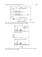
Phase stability of the Mach-Zehnder modulator measured using the Allan standard
deviation is shown in Fig. 9. The stability is independent of the input laser line-width for a
short fiber cable, the input lasers are a DFB-laser (10 MHz line-width) and a fiber-laser (1
kHz line-width).
Fig. 9. Measured phase stabilities of the Mach-Zehnder modulator, the first-order 22 GHz
signal and the second-order 100 GHz signal.
Advances in Lasers and Electro Optics
490
3.6 Differential polarization angle between two light-waves
The theme of this paper covers optical signal generation, but the ultimate goal of the
photonic system is generation of highly-stable optical signal and its transmission with fiber
system. The delay compensation must be performed on the delay caused during the optical
signal transmission through an optical fiber cable in order to keep the signals coherent. In
the photonic LO (Local) system, two optical signals are transmitted and converted by a
photo mixer at a remote antenna into a microwave signal. During the signal transmission
through the fiber cable, the cable length delay is caused, including Polarization Mode
Dispersion (PMD), a bottleneck in performing successful phase compensation (delay change
compensation). PMD is the state of polarizations (SOP) dispersing randomly in the cable.
PMD is caused when the state of polarization of the two optical signals is absolutely
changed by the movement of the cable through which the signals are transmitted. The
magnitude of PMD is inversely proportional to the degree of the polarization alignment of
the two optical signals. Since the generation of PMD contributes to the emergence of the
Differential Group Delay (DGD) (synonymous with LO phase jitter), SOP of the two signals
needs to be coincident so as to reduce the second order PMD effect on DGD.
We measured the differential polarization angle between two light-waves generated by the
Mach-Zehnder modulator. The measurement block diagram is shown in Fig. 10. In this
measurement, the two light-waves are transmitted to the ITU-Grid programmable optical
filter (Peleton QTM050C), which selects one of the two light-waves for polarization. The
polarization is measured by the polarization meter (Polarimeter). The differential angle is
calculated by Eq. (12): spherical trigonometry.
12 1 2 12
cos = sin sin cos cos cos( )d
δδ δδ λλ
×+×× − (12)
The measured polarization angles in degrees are (
δ
1
: -29.2 in Azimuth,
λ
1
: -4.54 in Elevation)
and (
δ
2
: -28.3,
λ
2
:-4.59). The calculated differential polarization angle: d is 0.90 degrees.
Fig. 10. Block diagram of the Polarization measurement. One of the two optical signals is
selected by the ITU grid switch for polarization and transmitted to the Polarization meter.
3.7 Astronomical application
3.7.1 Estimated coherence loss
The measured stability of the null-bias point operation mode is 2.4
×10
–14
(white phase
modulation noise) with 1.3
×10
–14
(white frequency modulation noise) at
τ
= 1 sec, while the
stability of the full-bias point operation mode is 3
×10
–14
(white phase modulation noise).
With respect to a
×n multiplier, multiplied phase noise (Vanblerkom & Aneman (1966))
should also be considered as shown below:
Photonic Millimeter-wave Generation and Distribution Techniques
for Millimeter/sub-millimeter Wave Radio Interferometer Telescope
491
M
ultiplied phase noise
=
M
easured phase noise Multiplied number× (13)
The coherence loss calculated from Equation (1) is smaller than 5% at the highest local
frequency (938 GHz).
In the Dual-Mixer Time Difference system for the null-bias point operation mode shown in
Fig. 7, phase noise of the measurement system (supposedly, white frequency modulation
noise) is not canceled out as common noise, because the signal phase becomes unstable and
incoherent in the amplification process by the AMP in the figure. The mild peak in 22 GHz
around 30 seconds is thought to be due to white frequency modulation noise or instability of
the amplifier, as the similar peak is not detected in the full-bias point operation (80 and 100
GHz measurements). Assuming the white frequency modulation noise is caused by any
component other than the Mach-Zehnder Modulator, the phase noise of the Mach-Zehnder
Modulator will be
σ
y
(
τ
= 1) = 2.4 × 10
–14
. In this case, the coherence loss due to the phase
noise will be constant, because the loss due to white phase modulation noise is independent
of integration time. However, even if both of these noises are considered, the Mach-Zehnder
modulator is still applicable to the most advanced systems such as ALMA and Very Long
Baseline Interferometer (VLBI). The photonic millimeter-wave generator has been authorized
as the MZM-LS (Mach-Zehnder Modulator scheme Laser Synthesizer) in ALMA project.
4. Round-trip phase stabilizer
Reference microwave signal or reference laser signal transfer via optical fiber have been
researching in many fields (Sato et al. (2000), Daussy et al. (2005), Musha et al. (2006),
Foreman et al. (2007)).
4.1 Basic concept of the round-trip phase stabilizer
Figure 11 shows the basic concept of the round-trip phase stabilizer(Kiuchi (2008)) for the
two coherent-optical-signals. The optical signals are transmitted in one single-mode fiber.
Under the effect of polarization mode dispersion (PMD), the transmission line lengths (the
length of the signal path in the optical fiber cable) are different between the two coherent-
optical-signals which are transmitted as a set.
The phase of these signals (
λ
1
and
λ
2
in wavelength) at the starting point of the roundtrip
transmission is assumed to be zero, and the phase of these signals which have returned to
the starting point are obtained from the following equations: [(2
π
m) +
φ
1
] for
λ
1
, and
[(2
π
n)+
φ
1
+2Φ] for
λ
2
, respectively, where m and n are integers and Φ is the variable which is
controlled by a phase shifter. The signal phase at the middle point of the roundtrip
transmission (at the other end of the fiber) can be expressed as follows: For
λ
1
, (
φ
1
/2): m is
even or [(
φ
1
/2) +
π
]: m is odd, and: For
λ
2
, [(
φ
2
/2) + Φ]: n is even or [(
φ
2
/2) +
π
+ Φ]: n is odd.
Therefore, the transmitted signal phase is (
φ
1
/2)–[(
φ
2
/2)+Φ] or (
φ
1
/2)–[(
φ
2
/2)+Φ]+
π
.
If we adjust the phase
Φ as follows;
12
=2.
φφ
+Φ
(14)
the signal phase at the antenna is the same as or just
π
different from the signal phase at the
starting point of the roundtrip transmission.
Advances in Lasers and Electro Optics
492
Fig. 11. Basic concept of the round-trip phase stabilizer. The two coherent-optical-signals (
λ
1
and
λ
2
) are transmitted in one single-mode-fiber. Under the effect of PMD, the transmission
line lengths (the length of the signal path in the optical fiber cable) are different between the
two coherent-optical-signals. The effect of PMD will be expressed in this figure.
4.2 Round-trip optical dual-differential phase measurement scheme
The basic configuration of the system is shown in Figure 12. Signals generated by the two
coherent-optical-signals generator in the previous section (Kawanishi et al. (2007),Kiuchi et
al. (2007)) are sent to the antennas from the base-station (ground unit), together with PMD
Fig. 12. The round-trip optical phase measurement scheme of the round-trip phase stabilizer.
Photonic Millimeter-wave Generation and Distribution Techniques
for Millimeter/sub-millimeter Wave Radio Interferometer Telescope
493
caused by the rotation and coupling of the fiber cross section signals. At each antenna,
frequency-shift modulation (
φ
PLO
, angular frequency is
ω
c
) is performed by the Acoust-
Optics frequency shifter for the received optical signals which are then reflected by the
optical reflector and returned to the shifter. The signals pass through one path in
transmission. The frequency shift modulation is used to distinguish the round-trip signal
from back-scattered signals. The phase difference between the signal at the starting point of
the roundtrip transmission and the returned signal is detected by Michelson’s
interferometry to perform correlation of the orthogonal signals which are generated by a 90-
degree phase shift of 2
ω
c
(50 MHz). These orthogonal signals are not required for the phase-
lock to the modulation signal at the antenna. Since the modulation frequency (2
ω
c
) is small,
its PMD (the second order PMD) can be ignorable (the estimated deviation value is shown
in the next subsection). The round-trip phase measurement method is helpful for successful
delay compensation of the microwave signal which is converted from the two coherent-
optical-signals by a photo mixer.
In this method, a Faraday-reflector or a mirror both can be used as the reflector at the antenna.
In the case of the Faraday reflector, the route of the transmitted and return of light are not
completely corresponding. This difference becomes a fixed phase offset. However, the change
of the phase offset can be compensated by the phase locked loop. The fixation phase offset
does not influence the transmitted phase stability. In the case of using the Faraday rotator and
a polarization splitter, it becomes advantageous with respect to the carrier noise ratio. The
influence such as back-scattering can be reduced by separating polarization.
4.2.1 Polarization mode dispersion (PMD)
Polarization mode dispersion (PMD) (Agrawal (2002),Derickson (1998)) is the state of
polarizations dispersing randomly in the cable. PMD arises from the anisotropic nature of
the fiber cross section (
θ
x
and
θ
y
). PMD mainly consists of two components 1st and 2nd-
order terms. The 1st-order component is differential group delay (DGD), and the 2nd-order
components are polarization chromatic dispersion. In contrast to group velocity dispersion,
PMD shows temporal change. PMD is caused when the state of polarization of the two
coherent-optical-signals is absolutely changed by the movement of the cable through which
the signals are transmitted.
We introduce two equations (Eqs. (15) and (17). The variance of differential group delay
(Agrawal (2002), Derickson (1998)), can be approximated to be
=
p
DL
τ
σ
(15)
Where Dp is the fiber PMD parameter of the optical fiber cable [
/ps km ], and L is the cable
length [km]. The variation of the delay will have a standard deviation of 39 fs (15 km fiber) if
we choose a fiber with the lowest PMD of 0.01
/ps km .
Second order PMD is the wavelength dependence of the propagation delay in the different
polarization modes. The birefringence of the optical fiber cable is wavelength dependent;
different wavelengths will cause different types of PMD. The deviation of the propagation
delay caused by the second order PMD is as follows (Ciprut et al. (1998));
2
2
2
2
=
3
p
cD
DL
λ
π
λ
Δ
(16)
Advances in Lasers and Electro Optics
494
Where
Δ
λ
is the frequency difference between the two coherent-optical-signals. The
deviation of the propagation delay caused by the second PMD is calculated as
22
=.
max max
DL
τλ
σ
×Δ × (17)
DGD is calculated as the co-variance of the two deviations of the propagation delay. The
maximum differential frequency of the two coherent-optical-signals is
Δ
max
= 1.1 nm. And
when the L
max
is 15 km,
2
τ
σ
is 0.74 fs.
In the case of the conventional technologies (Cliche & Shillue (2006)), as the round-trip
measurement is performed with either one of the two optical signals, the delay on the two
signals are compensated commonly by the fiber stretcher using the delay of the measured
signal only. On the other hand, in the basic concept of the proposed system (Figures 11 and
12), the delays (
τ
σ
and
2
τ
σ
) of the two signals are considered. The group delay
τ
σ
acts like
a common mode noise to the two coherent-optical-signals. In addition, the round trip delays
of the two coherent-optical-signals are measured and compensated independently, taking
the differential delay between two coherent-optical-signals into consideration (Figure 11).
4.2.2 Phase relational expression
Firstly, for the phase relationship of the signals in one of the two coherent-optical-signals in
Figure 11, the instrumental delay analysis is shown in Figure 12. The suffixes of the
equations (
λ
1 and
λ
2) indicate the optical wavelength.
The phase of the optical signal to be transmitted from the two coherent-optical-signals
generator is defined as
φ
0
(t).
011
()= () ,tt
λλ
φ
ω
φ
+ (18)
Where
ω
λ
1
is optical angular frequency, t is time, and
φ
λ
1
is initial/offset phase. If the time
delay caused in the roundtrip signal transmission through the optical fiber cable is assumed
to be
τ
1
,
τ
cable
(Figure 12), the received signal phase at the antenna is expressed as
φ
1
(t), at the
point of the photomixer at antenna.
111 21
()= ( )
cable
tt
λλ
φ
ωτττ
φ
−− − + (19)
At the antenna, the received signals are modulated (frequency-shifted) by a microwave
signal
φ
PLO
(25 MHz) and sent back to the ground unit through the optical cable.
()= () ,
P
LO c c
tt
φ
ω
φ
+ (20)
Where
ω
c
is a shift angular frequency (25 MHz), and
φ
c
is an initial phase. Frequency-shift of
φ
PLO
(t) is done by the Acoust-Optics frequency shifter. The signal phase at the reflector on
the antenna is as follow;
21 11 34
()=( ) ( )
c cable
tt
λλ
φ
ωω ωττ ττ
+− +++
41cc
λ
ωτ
φφ
−++
(21)
The signal is reflected by an optical reflector, and returned to the ground-unit via the same
cable in reciprocal process.
Photonic Millimeter-wave Generation and Distribution Techniques
for Millimeter/sub-millimeter Wave Radio Interferometer Telescope
495
Differential phase between transmission and reception signals is measured by the
Michelson’s interferometer. The above equation is established assuming that the signal (
λ
1)
is reflected by Fiber Brag Grating (FBG1) and is converted into microwave
φ
3
by the low-
frequency photo mixer to detect 2
ω
c
. The frequency (2
ω
c
) is selected by a microwave band
pass filters.
313465
()=2 () (2 2 2 )
c cable
tt
λ
φ
ωωτ ττττ
−+++−
3467
2( )2
ccable c
ωτ τ τ τ τ
φ
−+++++ (22)
This equation means that the roundtrip delay is measured as the optical differential phase of
the frequency (c/
λ
1, c: speed of light) after being converted to a microwave angular-
frequency (2
ω
c
).
Secondly, the phase relationship of the other optical signal (
λ
2) can be obtained in
conformity with Eqs. (18) to (22). When we use the two coherent-optical-signals, the cable
delay is different between
λ
1 and
λ
2 under the effect of PMD. In the following equations, the
cable delay in
λ
2 is shown with hat. Initial optical (
λ
2) signal is as follows:
022
ˆ
()= () ,tt
λλ
φ
ωφ
+ (23)
The phase of the optical signal at the antenna is expressed as
1
ˆ
()t
φ
.
121 22
ˆ
ˆˆ ˆ
()= ( )
cable
tt
λλ
φ
ωτττφ
−− − +
(24)
The optical modulation is performed simultaneously for the wavelength of the two signals
(
λ
1 and
λ
2) at the antenna, assuming that the optical signal passes through FBG1 and
detected as microwave
3
ˆ
φ
(t) by the other photo mixer.
323465
ˆ
ˆˆˆˆˆ
()=2 () (2 2 2 )
c cable
tt
λ
φ
ωωτ ττττ
−+++−
3468
ˆˆˆˆˆ
2( )2
ccable c
ωτ τ τ τ τ
φ
−+++++
(25)
This equation also means that the roundtrip delay is measured as the optical differential
phase of the frequency (c/
λ
2) which is then converted to a microwave angular-frequency
2
ω
c
.
Thirdly, Eq.(26) shows how to obtain the differential phase between
φ
0
(t) and
0
ˆ
φ
(t) at the
starting point of the roundtrip transmission (with the single mode fiber long cable over 10 km).
00 1 2 12
ˆ
() ()= () () ,tt t t
λλλλ
φφ
ωω
φφ
−−+− (26)
In Eq. (27), the differential phase between
φ
1
(t) and
1
ˆ
φ
(t) is that of the signal received at the
antenna.
11 1 2 12
ˆ
() ()=[ () () ]tt t t
λλλλ
φφ
ωω
φφ
−−+−
11 2 21 2
ˆˆ ˆ
()()
cable cable
λλ
ωτττωτττ
−+++ ++
(27)
Advances in Lasers and Electro Optics
496
Comparing Eqs. (26) and (27), it is clear what comprises the instrumental delay. The equation
for the phase change (
φ
d
) of the two optical signals caused in the transmission is as follows;
11 2 21 2
ˆˆ ˆ
=( ) ( ).
d cable cable
λλ
φ
ωτττωτττ
−+++ ++ (28)
On the other hand, half of the differential phase between
φ
3
(t) and
3
ˆ
φ
(t), or the double-
difference between the signals before/after the roundtrip transmission is as follows;
33 65
134
ˆ
() ()
=( )
22
cable
tt
λ
φφ
ττ
ωτ τ τ
−−
−+++
65
234
ˆˆ
ˆˆˆ
()
2
cable
λ
ττ
ωτ τ τ
−
++++
3467
(
ccable
ωτ τ τ τ τ
−++++
3468
ˆˆˆˆˆ
).
cable
τττττ
−−−−− (29)
If this differential phase is compensated, the coherent transmission from the ground unit to
the antenna can be realized. To compare Eq. (28) and Eq. (29), the term (
12
ˆ
cable cable
λλ
ωτ ωτ
−+ )
is compensated by Eq. (29) (measured data).
The residual phase in this method is as follows:
=
R
esidual phase
65 65
13 4 2 3 4
ˆˆ
ˆˆ
()()
22
λλ
ττ ττ
ωτ τ ωτ τ
−−
−++ + ++
(30)
334466
ˆˆˆˆ
()
c cable cable
ωτ τ τ τ τ τ τ τ
−−+−+−+−
(31)
78
ˆ
().
c
ωτ τ
−− (32)
Lastly, the meanings of these equations are described below.
Eq.(30) shows the second order PMD of the cable whose length is (
τ
3
+
τ
4
+ (
τ
6
–
τ
5
)/2),
Eq.(31) shows the
ω
c
(25 MHz) phase drift equivalent to the second order PMD of the cable
length obtained by (
τ
cable
+
τ
3
+
τ
4
+
τ
6
),
Eq.(32) shows the
ω
c
(25 MHz) phase difference equivalent to the phase drift of the cable
length obtained by (
τ
7
–
8
ˆ
τ
).
Equations (30) and (32) are ignorable: the change of the differential delay is ignorable,
because the length of [
τ
3
,
τ
4
,
τ
5
,
τ
6
,
τ
7
and
τ
8
] is a few meters and not long enough to cause
problems. Equation (31) is almost equal to Eq. (33).
ˆ
()
c cable cable
ωτ τ
− (33)
This value is the inevitable error of this method. According to the Equations (15) and (17),
the offset frequency in the round-trip signal (2
×
ω
c
=50 MHz) is Δ
λ
offset
= 0.0004 nm. The
deviation of the propagation delay
2
τ
σ
is less than 0.003 fs, which is very small.
Photonic Millimeter-wave Generation and Distribution Techniques
for Millimeter/sub-millimeter Wave Radio Interferometer Telescope
497
In the process, the effect of the first and second order PMD can be reduced by using double-
difference of the independently measured phases of two optical signals of round-trip
measurement.
As a result, we can measure the instrumental delay phase (twice of the cable delay phase).
Moreover, this method does not require the transmission of the modulation signal (
ω
c
),
which means we do not have to consider any phase delay of the modulation signal (
ω
c
). The
measured phase is used to compensate the instrumental delay change and phase change.
4.3 Two optical signal separation and optical phase control scheme
If we use a fiber stretcher that stretches the two signals together and performs phase shift on
both of them, it is hard to get an enough dynamic range of the phase shift. On the other
hand, in our basic concept (Fig. 11) using a phase shifter (General Photonics FPS-001)
instead of the fiber stretcher, the phase shift is performed on only one of the two optical
signals (
λ
1
and
λ
2
). Figure 13 shows the execution example. Transmission delay on the fiber
is measured as the differential phase of the optical round-trip delay of each lightwave
signal. At first, the two coherent-optical-signals have a vertical and high-extinction ratio
polarization. In a series of processing in the ground unit, the polarization is maintaining.
The signal flow is shown in Figure 13.
Fig. 13. Two optical signal separation and optical phase control scheme. Where CP1, CP2,
CP3: optical coupler, C1, C2, C3: circulator, P1, P2: polarization beam splitter, and FBG1,
FBG2: fiber bragg grating
The character in parentheses means an optical device in the figure. The signal, passing
through the optical coupler (CP1), circulator (C1), and polarization beam splitter (P1), is
divided into two wavelengths (
λ
1
and
λ
2
). Wavelength
λ
1
signal is reflected by a fiber bragg
Advances in Lasers and Electro Optics
498
grating (FBG1) and returned to the beam splitter (P1), while wavelength
λ
2
signal is reflected
by a fiber bragg grating (FBG2) and returned to the beam splitter (P1) via the phase-shifter.
The returned light-waves are recombined at the beam splitter (P1) and sent to the circulator
(C1), and then, to the polarization beam splitter (P2). The signal is divided into two signals
at the optical coupler (CP2) after passing through a long single-mode fiber. One of the
divided signals is converted to a millimeter wave by a photo-mixer, and the other signal is
reflected by a Faraday reflector after the frequency shift by an optical frequency shifter
(Acous-Optics frequency shifter). The reflected signal is converted into a 90-degree different
optical polarization signal by the Faraday reflector. The signal, after passing through the
frequency shifter again, is returned back to the polarization beam splitter (P2) in the ground
unit. As the signal goes through the optical reciprocal process, the received signal has a
horizontal (90-degree different polarization angle to the transmission signal) polarization at
this point. After passing through the circulator (C2) and the beam splitter (P1), the signal is
divided into two wavelengths (
λ
1
and
λ
2
) again. As described above, wavelength
λ
1
signal is
reflected by the fiber bragg grating (FBG1) and returned to the beam splitter (P1), while
wavelength
λ
2
signal is reflected by FBG2 and returned to the beam splitter (P1) via the
phase-shifter. The returned light-waves are recombined again at the beam splitter (P1) and
sent to the circulator (C2) because the optical polarization is horizontal. And, finally the
signal is recombined with the divided transmission signal at the optical coupler (CP3).
The differential phases on the angular frequency 2
ω
c
between transmission and round-trip
signals on each light-wave signal are detected by low-frequency photo-mixers after
wavelength separation by the FBG1 optical filter (see previous Section). These measured
phases are equivalent to the round-trip phases on both lightwave signals. In the proposed
method, the transmitted signal will be stabilized by controlling the differential phase on the
measurement signals to zero.
According to our experiments, a polarization controller is put into place between P1 and
FBG1 produce a good effect.
4.4 Laboratory tests
A block diagram of the performance measurement system is shown in Figure 14. A set of the
two coherent-optical-signals generated is divided into two signals: one is transmitted to the
phase stabilizer system and the other to the photo mixer (Nippon Telephone and Telegraph
(NTT) unitraveling-carrier photo-diode(Hirota et al. (2001),Ito et al. (2000))) as a reference
signal. The signal passes through a 10-km Single-Mode Fiber cable with/without the phase
stabilizer.
4.4.1 Phase stability measurements (Laboratory test)
We measured the phase stability (Fig. 15) of the transmitted signal (80 GHz) at the antenna
through the single mode fiber cable (10 km) in the time-domain Allan STD method(Allan
(1966), Allan (1976)) by a time interval analyzer: TSC-5110A. The measurements were
conducted with/without the phase stabilizer to check the improvement of the phase
stabilizer in the interferometric system.
When the optical signal (80 GHz) is transmitted through the single mode fiber cable (10 km),
the phase stability begins to degrade around 10 seconds integration time. In the case of
using the phase stabilizer, the degradation of the phase stability is staved off. The measured
phase noise is the white phase noise.
Photonic Millimeter-wave Generation and Distribution Techniques
for Millimeter/sub-millimeter Wave Radio Interferometer Telescope
499
Dynamic range of this method was measured by using a manual controlled air-gap stretcher
which was inserted between the Ground unit and the single mode fiber spool in Figure 14.
The measured dynamic range was larger than 5 cm.
Fig. 14. A block diagram of phase stability measurement system. The signal is provided
from the two coherent-optical-signals generator.
Fig. 15. The 80 GHz phase stability that passed through the 10 km fiber. The phase stability
begins to degrade around 10 seconds integration time. In the case of using the phase
stabilizer, the degradation of the phase stability is staved off.
Advances in Lasers and Electro Optics
500
4.4.2 Phase stability measurements (Field test)
In ALMA OSF (Operations Support Facility: 2900m sea level), there are built-up antennas
and a Holography system which measures the antenna surface accuracy. The Photonic
system field test was carried out using the Holography signal and two antennas (Antenna-1
and Antenna-4). The experiment block diagram is shown in Figure 16. The Holography
transmitter, Antenna-2, Antenna-1 and Antenna-4 are standing in a low. Therefore the
received Holography signals at Anttena-1 and Antenna-4 are blocked by Antenna-2, the
received Holography signal levels are very weak. However Anttena-1 and Antenna-4 can
receive the Holography signal simultaneously.
Fig. 16. Block diagram of the phase stability measurement experiment with the Holography
transmitter. The Holography transmitter faces Antenna-2, with Antenna-1 and Antenna-4
aligned behind antenna-2. Two antennas can receive the Holography signal simultaneously.
In this experiment, the Holography signal was the common signal. Differential phase of
Holography signal between Anttena-1 and Antenna-4 was measured. Received Holography
signals (104.02 GHz) were converted down to intermediate frequency (IF: 50 MHz) signals
by using the provided photonic signal from the Photonic millimeter-wave generator via the
Round-trip phase stabilizer. The differential signal phase of these 50 MHz signals are
measured by DMTD method. The measured phase stability is shown in Figure 17. The phase
noise of 10
–13
in White-PM noise was obtained, which is the covariance phase noise of two
antenna system.
4.5 Verification results
In the ALMA Specification, instrumental delay/phase error on the 1st Local oscillator
should be 53 fs (rms) in the short term, and long term drift should be 17.7 fs between 10 sec
averaging at intervals of 300 seconds:
σ
y
(1 sec) < 9.2 × 10
–14
. On the other hand, in the very
long baseline interferometer (Rogers & Moran (1981), Rogers et al. (1984)) (VLBI), the
requirements of 320 GHz are as follows:
σ
y
(1 sec) < 2 × 10
–13
,
σ
y
(100 sec) < 1.3 × 10
–14
and
σ
y
(1000 sec) < 3 × 10
–15
.
Photonic Millimeter-wave Generation and Distribution Techniques
for Millimeter/sub-millimeter Wave Radio Interferometer Telescope
501
Fig. 17. The measured phase stability is measured by DMTD. The measured stability shows
the co-variance of two antenna system stability. Received Holography signal (104.02 GHz)
was converted down to 50 MHz by using the provided photonic signal from the Photonic
millimeter-wave generator via the Round-trip phase stabilizer.
The verifications matrix is shown in Table 2. The measured values meet the ALMA
specifications.
Table 2. Verifications matrix.
5. Conclusion
Based on our experiment results, we propose a new high carrier suppression optical
doublesideband intensity modulation technique using the integrated LiNbO
3
Mach-Zehnder
modulator which is capable of compensating the imbalance of the Mach-Zehnder arms with
a pair of active trimmers (null-bias operation mode). The full-bias point operation mode
introduced in this paper is also a novel modulation technique for the second-order harmonic
generation. The Mach-Zehnder modulator can generate two coherent light waves with
frequency difference equivalent to four times the modulation frequency. Photonic local
signals of 120GHz can also be generated using this technique.
Advances in Lasers and Electro Optics
502
The two spectral components of the two optical signals generated with this technique are
phase-locked without using any complicated feedback control. All of the measurements
were carried out on a table (without vibration isolation) in a normally air-conditioned room
without acoustic noise isolation. In short, all of the measurements were performed under
normal environment. Temperature change and mechanical vibrations may have affected the
output lightwaves to some degree, however there was no chaotic phenomenon such as
mode hopping or mode competition during the experiments. Based on these results, we
concluded that the proposed techniques will be useful to construct a robust, low-cost and
simple setup for the photonic local signals.
Compensation of the Local signal transmission delay is an indispensable technique for
accurate interferometrical observation. PMD delay, which is caused during the signal
transmission, needs to be reduced because it deteriorates the accuracy of the delay amount
by affecting the signal polarization and wavelength. The two coherent-optical-signals
generator (Kawanishi et al. (2007), Kiuchi et al. (2007)) is required to help stabilization of
polarization, and to maintain the high extinction ratio, and to keep the signal state of
polarizations in stable condition for preventing the delay generation.
We proposed the double difference phase measurement method. The method is also
available to use the fiber stretcher instead of the phase shifter. The Double-difference
method is more robust to external influences and more accurate than the current scheme
which uses one of the two optical signals for measurement. This method can reduce
deterioration in the signal phase stability caused by the long fiber signal transmission.
The performance advantages of the system are:
1. The modulation signal (
ω
c
) transmission and its phase compensation are not required
(the modulation signal on the antenna is generated by a free-running oscillator);
2. External noise (acoustic noise, vibration noise) on the long single mode fiber cable is
dealt with a common noise; and
3. The PMD problems are reduced, as the round trip delays on the two optical signals are
measured and compensated independently.
6. References
Alferness,R.C.(1982), Waveguide electro-optic modulators, IEEE Trans. Microw. Theory Tech.,
vol.30, no.8, pp.1121-1137.
Agrawal,G.P.(2002), Fiber optic communication system, third edition, JohnWiley & Sons Inc.
Allan, D.W. (1966), Statistics of Atomic Frequency Standards, Proc. IEEE, vol.54, pp.221.
Allan, D.W.(1976), Report on NBS dual mixer time difference system (DMTD) built for time
domain measurements associated with phase 1 of GPS, NBS IR, vol.75, pp.827.
Ciprut,P., Gisin,B., Gisin,N., Passy,R., Von der Weid,J.P., Prieto,F., & Zimmer,C.w.(1998),
Second-order polarization mode dispersion: Impact on analog and digital
transmissions, IEEE Journal of lightwave technology, vol.16, no.5, pp.757-771.
Cliche,J., & Shillue,B.(2006), Precision timing control for radioastronomy, maintaining
femtosecond synchronization in Atacama Large Millimeter Array, IEEE control
system magazine, pp.19-26.
Daussy,C., Lopez,O., Amy-Klein,A., Goncharov,A., Guinet,M., Chardonnet,C., Narbonneau,
F., Lours,M., Chambon,D., Bize,S., Clairon,A., & Santarelli,G.(2005), Long-Distance
Frequency Dissemination with a Resolution of 10
–17
, Physical review letters, vol.94,
203904.
Photonic Millimeter-wave Generation and Distribution Techniques
for Millimeter/sub-millimeter Wave Radio Interferometer Telescope
503
Derickson,D., Fiber optics test and measurement, Prentice Hall PTR.
Fonseca,D.D., Monteiro,P., Cartaxo,A.,V.,T., & Fujita,M.(2004), Single sideband
demonstration using a four phase-modulators structure, 2004 IEEE/LEOS workshop
on advanced modulation formats, FC2.
Foreman,S.M., Ludlow,A.D., de Miranda,M.H.G., Stalnaker,J.E., Diddams,S.A., &
Ye,J.(2007), Coherent optical phase transfer over a 32-km fiber with 1-s instability at
10
–17
, Physics review letters,DOI:10.1103/PhysRevLett.99.153601.
Healey, D.J.III (1972), Flicker of frequency and phase and white frequency and phase;
Fluctuations in frequency sources, Proc. 25th Annu. Sympo. On Frequency Control
(ASFC), pp.29-42.
Hirota,Y., Ishibashi,T., & Ito,H.(2001), 1.55-um wavelength periodic traveling-wave
photodetector fabricated using unitraveling-carrier photodiode structures, IEEE J.
of Lightw. Technol, vol.19, pp.11.
Ito,H., Furuta,T., Kodama,S., & IshibashiT.(2000), InP/InGaAs uni-travelling-carrier
photodiode with 310 GHz bandwidth, Electron. Lett., vol.38, no.21, pp.1809-1810.
Izutsu,M., Yamane,Y., & Sueta,T.(1977), Broad-band travering-wave modulator using
LiNbO
3
optical waveguide, IEEE J. Quantum Electron., vol.13, no.4, pp.287-290.
Izutsu,M., Shikamura,S., & Sueta,T.(1981), Integrated optical SSB modulator/frequency
shifter, J. Quantum Electron., vol.17, pp.2225-2227.
Jiang,Q., & Kavehrad,M.(1993), A Sub-carrier-Multiplexed Coherent FSK System Using a
Mach-Zehnder Modulator with Automatic Bias Control, IEEE/LEOS Photonics Tech.
Let. Journal, vol.5, no.8, pp.941-943.
Kawaguchi, N. (1983), Coherence loss and delay observation error in Very-Long-Baseline
Interferometry, J. Rad. Res. Labs., vol.30, no.129, pp.59-87.
Kawanishi,T., Sakamoto,T., Shinada,S., Izutsu,M., Higuma,K., Fujita,T., &
Ichikawa,J.(2004a), LiNb
3
high-speed optical FSK modulator, Electron. Lett., vol.40,
pp.691-692.
Kawanishi,T., & Izutsu,M.(2004b), Linear single-sideband modulation for high-SNR
wavelength conversion, Photon. Technol. Lett., vol.16, pp.1534-1536.
Kawanishi,T., Kiuchi,H., Yamada,M., Sakamoto,T., Tsuchiya,M., Amagai,J., &
Izutsu,M.(2005), Quadruple frequency double sideband carrier suppressed
modulation using high extinction ratio optical modulators for photonic local
oscillators, MWP 2005, PDP03.
Kawanishi,T., Sakamoto,T., Miyazaki,T., Izutsu,M., Fujita,T., Mori,S., Higuma,K., &
Ichikawa,J. (2006), High-speed optical DQPSK and FSK modulation using
integrated Mach-Zehnder interferometers, Optics Express, vol.14, no.10, pp.4496-
4478.
Kawanishi,T., Sakamoto,T., & Izutsu,M. (2007), High-speed control of lightwave amplitude
phase and frequency by use of electrooptic effect, IEEE Journal of selected topics in
quantum electronics, vol.13, no.1, pp.79-91.
Kiuchi,H., Kawanishi,T., Yamada,M., Sakamoto,T., Tsuchiya,M., Amagai,J. &
Izutsu,M.(2007), High Extinction Ratio Mach-Zehnder Modulator Applied to a
Highly Stable Optical Signal Generator, IEEE Trans. Microwave Theory and
Techniques, vol.55, no.9, pp.1964-1972.
Advances in Lasers and Electro Optics
504
Kiuchi,H.(2008), Highly stable millimeter-wave signal distribution with an optical round-
trip phase stabilizer, IEEE Trans. Microwave Theory and Techniques, vol.56, no.6,
pp.1493-1500.
Lim,C., Nirmalathas,A., Novak,D., & Waterhouse,R.(2000), Optimisation of baseband
modulation scheme for millimeter-wave fibre-radio systems, Electron. Lett., vol.36,
pp.442-443.
Musha,M., Sato,Y., Nakagawa,K., Ueda,K., Ueda,A., Ishiguro,M., Robust and precise length
stabilization of a 25-km long optical fiber using an optical interferometric method
with a digital phase-frequency discriminator, Appl. Phys. B, vol.82, pp.555-559.
Onillon,B., Constant,S., & Llopis,O., Optical links for ultra low phase noise microwave
oscillators measurement, IEEE frequency control symposium.
Rogers, A.E.E. & Moran, J.M. (1981), Coherence limits for very-long-baseline interferometry,
IEEE Trans. Instrum. Meas., vol.30, no.4, pp.283-286.
Rogers, A.E.E., Moffet, A.T., Backer ,D.C. & Moran, J.M. (1984), Coherence limits in VLBI
observation at 3-millimeter wavelength, Radio Science, vol.19, no.6, pp.1552-1560.
Sakamoto,T., Kawanishi,T., & Izutsu,M.(2005), Optical minimum-shift-keying with external
modulation scheme, Opt. Exp., vol.13, pp.7741-7747.
Sato,K., Hara,T., Kuji,S., Asari,K., Nishio,M., & Kawano,N.(2000), Development of an ultra
stable fiber optic frequency distribution system using an optical delay control
module, IEEE Trans. Inst. Meas., vol.49, no.1, pp.19-24.
Vanblerkom,R., & Aneman,S.,L.(1966), Considerations for the short term stability of
frequency multiplication, IEEE AES-2, vol.1, pp.36-47.
Vegas Olmos,J.,J., Tafur Monroy,I., & Koon,A.M.J.(2003), High bit-rate combined FSK/IM
modulated optical signal generation by using GCSR tunable laser sources, Opt.
Exp., vol.11, pp.3136-3140.
22
Quantum Direct Communication
Gui Lu Long
1,2
, Chuan Wang
1,3
, Fu-Guo Deng
4
, and Wan-Ying Wang
1
1
Key Laboratory of Atomic and Molecular Nanosciences and Department of Physics,
Tsinghua University, Beijing 100084,
2
Tsinghua National Laboratory for Information Science and Technology, Beijing 100084,
3
School of Science and Key Laboratory of Optical Communication and Lightwave
Technologies, Beijing University of Posts and Telecommunications, Beijing, 100876,
4
Department of Physics, Beijing Normal University, Beijing 100875,
People's Republic of China
1. Introduction
Quantum key distribution (QKD) is considered as an ideal method to make secret message
unreadable to eaves-dropper but intelligible to the two authorized parties of the
communication [1-6]. In the research of experimental quantum key distribution, single
photons and entangled photon pairs are used as the carriers. In quantum key distribution,
secret keys are generated first between the communication parties. The security of quantum
key distribution is guaranteed by the laws of quantum mechanics. After the quantum key
distribution is completed, the communication parties should share secret keys, then the
sender encrypts the secret message using the secret keys to form the ciphertext and
transmits the ciphertext through a classical channel. The receiver receives the ciphertext and
then decrypt the ciphertext to get the secret message. Altogether there are four steps in a
secret communication process with QKD: key generation, encryption, transmission and
decryption.
Here in this review, we review some new development in quantum communication,
quantum direct communication (QDC). Quantum direct communication is a form of
quantum communication where secret messages can be transmitted through a quantum
channel with or without additional classical communications. There are two forms of
quantum direct communication, quantum secure direct communication (QSDC) [7{9] and
deterministic secure quantum communication (DSQC) [10, 11]. In QSDC, secret messages
are transmitted directly between the communication parties, from sender Alice to receiver
Bob, without additional classical communication except those for the necessary
eavesdropping check. In other words, the quantum key distribution process and the
classical communication of ciphertext are condensed into one single quantum
communication procedure in QSDC. Deterministic secure quantum communication is
another type of quantum direct communication, such as those proposed in Ref. [10, 11],
where classical communication is required in order to read out the secret message. As
mentioned earlier, to complete a secure communication with the help of QKD, one usually
encodes the secret message with an encryption scheme, and the ciphered text is transmitted
through a classical channel. With a quantum channel, this procedure can be varied. For
Advances in Lasers and Electro Optics
506
instance, Alice can encrypt her secret message with a random key and encodes the
ciphertext into the quantum states of the information carriers. The ciphertext is then sent
from Alice to Bob deterministically. Alice also sends the random key to Bob through a
classical channel. With this knowledge, Bob can decode the message from the ciphertext
obtained through the quantum communication. Quantum principle ensures that Eve cannot
steal the ciphertext. Because the ciphertext needs be transmitted through a quantum channel
deterministically, not all quantum key distribution can be adapted to construct DSQC. Only
deterministic QKD schemes can be adapted for DSQC purposes. The fundamental difference
between QSDC and DSQC is the need of another round of classical communication. Hence it
is always possible to use a QSDC scheme as a DSQC scheme.
The first QSDC protocol is the two-step QSDC protocol where qubits in an EPR pair are sent
from one user to another user in two steps [8, 9]. The two-step QSDC protocol was first
proposed by Long and Liu in 2001 [8], and standardized and analyzed by Deng, Long and
Liu in 2003 [9]. Another QSDC protocol is the ping-pong QSDC protocol where one qubit of
an EPR pair is sent from one user to another and then back to the sender again like the ping-
pong. While the two-step QSDC protocol uses all four dense coding operations, the ping-
pong protocol uses only two of the four dense coding operations. In another development,
Shimizu and Imoto proposed the first DSQC protocol using entangled photon pairs [10]. In
their scheme, the ciphertext is encoded in the state of entangled pairs, and the photons are
transmitted from Alice to Bob. The receiver Bob performs a Bell-basis measurement to read
out the partial information. Full information of the ciphertext is read out after Alice notifies
him the encoding basis through a classical communication. In 2002, Beige et al. [11]
proposed another DSQC scheme based on single photon two-qubit states. The message can
be read out only after a transmission of an additional classical information for each qubit. In
recent years, quantum direct communication has attracted extensive interests and many
interesting and important works have been carried out in QSDC for instance in Refs. [12-30],
and in DSQC for instance in Refs. [31-39]. In the following sections, we will focus on the
development of these two forms of quantum direct communication. We will also discuss
their applications, such as in quantum secret sharing and quantum network.
2. Deterministic secure quantum communication protocols
As mentioned above, there are two kinds of deterministic schemes. One is quantum secure
direct communication (QSDC) in which the receiver can read out the secret message
directly, and classical information is exchanged between the two parties of quantum
communication only for security checking. The other is called deterministic secure quantum
communication (DSQC) [31] in which the receiver can read out the secret message by
exchanging at least an additional bit for each qubit, i.e. classical communication is needed
besides eavesdropping check. To some extent, DSQC process is similar to the QKD protocol
which is used to create a random key first and then use it to encrypt the message. In the
following, we will describe some DSQC protocols.
A. DSQC with nonmaximally entangled states
We describe here two DSQC protocols without using maximally entangled states which was
proposed by Li et al. [31], following some ideas in the delay-measurement quantum
communication protocol [40]. It utilizes the pure entangled states as quantum information
Quantum Direct Communication
507
carriers, called the pure-entanglement-based DSQC, and the other one makes use of the d-
dimensional single photons, called the single-photon-based DSQC. Both of them introduce
the decoy photons [41, 42] for security checking and only single-photon measurements are
required for the two communication parties.
The two parties use pure entangled states as the quantum information carries in the pure-
entanglement-based DSQC protocol [31]. Also this protocol assumes that the receiver has
the capability of making single-particle measurements. The pure entangled states can be
described as
(1)
where the subscript A and B indicate the two correlated photons in each entangled state. |0〉
and |1〉 are the two eigenvectors of the two-level operator σ
z, say the basis Z. a and b satisfy
the relation |a|
2
+ |b|
2
= 1.
Firstly, the sender, say Alice prepares a sequence of ordered N two-photon pairs, and each
pair is randomly in one of the two pure entangled states |Ψ’〉
AB, |Ψ’’〉AB, and
(2)
Alice picks up A particles to form an ordered sequence S
A and picks up the other partner
photons to form the sequence S
B. For security checking, Alice replaces some photons in the
sequence S
B with her decoy photons Sde which are produced randomly in one of the four
states {|0〉, |1〉, |+〉, |–〉}. Here |±〉 =
(|0〉 ± |1〉) are the two eigenvector of the two-level
operator σ
x, say the basis X. The decoy photons is easily prepared from the pure entangled
quantum system |Ψ〉
AB by taking a single-photon measurement on the photon A and
manipulating the photon B with some unitary operations. Secret message is encoded on the
photons in S
B sequence by performing I = |0〉〈0| + |1〉〈1| or σx = |1〉〈0| + |0〉〈1| at Alice's side
and the two unitary operations represent classical bits 0 or 1, respectively. Then Alice sends
sequence S
B to Bob. After Bob receives SB sequence, Alice and Bob check the security of
communication by measuring the decoy photons and comparing the outcomes. If the error
rate is lower than the security bound, Alice and Bob measure their remaining photons with
basis Z, and they get the final results R
A and RB, respectively. Alice announces her results
R
A. Then Bob reads out the secret message MA as MA = RA ⊕ RB ⊕ 1. As this scheme
requires only single-photon measurements and pure entangled quantum signals, it is far
more convenient than the schemes with entanglement swapping and quantum teleportation,
and it is more feasible in practice. In this protocol, the information carriers in two-particle
pure entangled states can be prepared in experiment easily with present technology, and a
single-photon measurement is simpler than a multi-particle joint measurement at present.
This protocol is also generalized to the case with d-dimensional quantum systems [31]. The
intrinsic efficiency approaches 100% and the total efficiency exceeds
in theory which is
larger than congeneric schemes using Einstein-Podolsky-Rosen (EPR) pairs.
B. DSQC with single photons
In the single-photon-based DSQC protocol [31], d- dimensional single-photon quantum
systems are utilized as the information carriers. The Z
d basis of a d- dimensional system is
Advances in Lasers and Electro Optics
508
(3)
The d-dimensional eigenvectors of the measuring basis X
d are
(4)
At first, sender Alice prepares a sequence of d-dimensional single-photons randomly in the
eigen-basis states of Z
d or Xd operators, the sequence is labeled as S. She chooses some
photons in the S-sequence as the decoy photons and encrypts her secret message M
A on the
other photons with unitary operations U
m,
, where
(5)
(6)
In other words, Alice encodes her message with U
m if the photon is prepared with the Zd basis.
Otherwise, she will encode the message with
. Then Alice sends the S sequence to Bob.
After the transmission, they check the eavesdropping by measuring the decoy photons and
analyzing the error rate. If the transmission is secure, Alice tells Bob the original states of the
photons. Then Bob measures them with the suitable bases and reads out the secret information
M
A with his outcomes. This protocol is more convenient in practical applications in virtue of
that it only requires the parties to prepare and measure single photons.
C. DSQC with quantum teleportation and entanglement swapping
Quantum teleportation [43] has been studied widely since it was first proposed in 1993, and
has been applied in some other quantum communication branches, such as QKD, quantum
secret sharing (QSS) and so on. In 2004, Yan et al. put forward a DSQC scheme using EPR pairs
and quantum teleportation [32]. In their scheme, the qubits do not carry the secret message
when they are transmitted between the two parties, and this makes this communication more
secure and convenient for post-processing such as privacy amplification.
At first, the two parties share a set of entangled pairs randomly in one of the four Bell states.
Suppose that all the EPR pairs used in the scheme are |φ
+
〉AB. The sender Alice prepares a
Quantum Direct Communication
509
sequence of C particles in the X basis |ψ〉
C according to her secret message (|+〉 for "0", |–〉 for
"1"). Then Alice performs Bell-state measurements on her two particles BC. Each outcome
will appear with equal probability 0.25 and Bob's particles will be related to the initial states
of particles C by a unitary transformation U
ij relying on Alice's measurement outcomes.
After Alice publicly announces her out-comes, Bob applies the corresponding inverse
transformation
to his particles and measures them with the basis X ≡ {|+〉, {| –〉}. Then
Bob can obtain Alice's message. The security of this scheme is ensured because the security
of quantum channel is ensured before the trans- mission of secret message, hence it is
completely secure.
Subsequently, Gao et al. proposed another direct secure quantum communication scheme
using controlled teleportation [20]. Three-particle entangled states are used in this scheme.
When the communication starts, the three parties first share a set of entangled states. The
sender Alice performs a Bell-state measurement on a information particle and a particle in
the entangle state, and the controller Charlie performs a single-particle measurement.
According to their measurement outcomes, the receiver Bob chooses a suitable unitary
operation and then takes a single-particle measurement on his particle for reading out the
secret message.
Entanglement swapping is also exploited to design a deterministic secure quantum
communication protocol [35]. The protocol also uses the maximally entangled EPR pairs as
the information carriers. The two parties assume that each of the four unitary operation
represents a two-bit classical information beforehand. Bob prepares a series of EPR pairs in
the state |Ψ
+
〉AiBi =
(|01〉 + |10〉)
AB and sends the A sequence to Alice which consists of all
the A particles in the EPR pairs. They both store the photons into two groups, i.e. photons A
1
and A
2
as a group and B
1
and B
2
as another group. In the case that the transmission is secure,
Alice performs her two-bit encoding via local unitary operation on one photon of each group.
Then they perform the Bell-state measurement on each group of their own particles. Alice
announces her measurement results to Bob. Bob then concludes Alice's operation according to
his measurement outcomes and those published by Alice, and extracts the secret message. This
protocol makes use of two EPR pairs for entanglement swapping. For two bits of information,
four qubits were prepared and two additional bits are transmitted.
Quantum teleportation or entanglement swapping can be utilized in DSQC schemes because
they have the same advantages that the security of communication is based on the security of
the process for sharing the entanglements, so that they can ensure the security before the secret
message communication. Once entanglement is established, the qubits do not suffer from the
noise and the loss aroused by the channel again, the bit rate and the security will very high.
D. DSQC based on the rearrangement of orders of particles
In this part, we describe DSQC protocols based on the rearrangement of orders of particles
which uses EPR pairs as the information carriers, following some ideas in the controlled-
order-rearrangement-encryption QKD protocol [6].
One DSQC protocol uses EPR pairs [21]. The transmitting order of the particles which
ensures the security of communication is secret to anyone except for the sender Bob himself.
The two parties agree that the four unitary operations in the dense coding represent two bits
of classical information. The receiver Alice prepares a sequence of EPR pairs randomly in
one of the four Bell states {|φ
±
〉AB, |ψ
±
〉AB}. Here