Báo cáo hóa học: " Impacts of Post-metallisation Processes on the Electrical and Photovoltaic Properties of Si Quantum Dot Solar Cells" potx
Bạn đang xem bản rút gọn của tài liệu. Xem và tải ngay bản đầy đủ của tài liệu tại đây (552.91 KB, 6 trang )
NANO EXPRESS
Impacts of Post-metallisation Processes on the Electrical
and Photovoltaic Properties of Si Quantum Dot Solar Cells
Dawei Di
•
Ivan Perez-Wurfl
•
Angus Gentle
•
Dong-Ho Kim
•
Xiaojing Hao
•
Lei Shi
•
Gavin Conibeer
•
Martin A. Green
Received: 14 June 2010 / Accepted: 15 July 2010 / Published online: 1 August 2010
Ó The Author(s) 2010. This article is published with open access at Springerlink.com
Abstract As an important step towards the realisation of
silicon-based tandem solar cells using silicon quantum dots
embedded in a silicon dioxide (SiO
2
) matrix, single-junc-
tion silicon quantum dot (Si QD) solar cells on quartz
substrates have been fabricated. The total thickness of the
solar cell material is 420 nm. The cells contain 4 nm
diameter Si quantum dots. The impacts of post-metallisa-
tion treatments such as phosphoric acid (H
3
PO
4
) etching,
nitrogen (N
2
) gas anneal and forming gas (Ar: H
2
) anneal
on the cells’ electrical and photovoltaic properties are
investigated. The Si QD solar cells studied in this work
have achieved an open circuit voltage of 410 mV after
various processes. Parameters extracted from dark I–V,
light I–V and circular transfer length measurement (CTLM)
suggest limiting mechanism in the Si QD solar cell oper-
ation and possible approaches for further improvement.
Keywords Silicon Á Quantum dots Á Solar cells Á
Third generation Á Electrical characterisation
Introduction
The concept of a tandem solar cell has been well developed
as a method of improving solar cell efficiency. In a tandem
cell, solar cells of different band gaps are stacked on top of
one another. The cell with the highest band gap is placed
on the top, while the cell with the lowest band gap is
positioned at the bottom of the tandem stack. Each cell
absorbs the light it can most effectively convert, with the
rest passing through to the underlying cells [1]. The highest
efficiency cells to date are tandem cells made using single
crystal III-V materials. These materials are grown by very
expensive epitaxial techniques.
An ‘all-Si’ tandem solar cell makes use of inexpensive
silicon thin-film technology in combination with a high-
efficiency multi-band gap approach. It takes the advantage
of quantum confinement effects in silicon. When silicon is
made very thin (of the order of a few nanometers) in one or
more dimensions, quantum confinement causes its effective
bandgap to increase. The strongest effect is obtained when
silicon is confined in 3D (i.e., quantum dots). If the quantum
dots are close to each other, carriers can tunnel between
them to form quantum dot superlattices which can be used
as the higher bandgap cells in a tandem stack (Fig. 1)[2].
A simple approach to make Si quantum dot super lattices
has been described by Zacharias et al. [3]. Similar multi-
layer structure was also suggested for the formation of
InGaAs quantum dots [4]. The effective bandgap of silicon
thin films made this way can be varied by varying the size of
the quantum dots. This effect has been supported by pho-
toluminescence (PL) measurements (Fig. 2)[1, 5].
As an encouraging step towards the realisation of sili-
con-based tandem solar cells using silicon quantum dots
embedded in a silicon dioxide (SiO
2
) matrix, single-junc-
tion silicon quantum dot (Si QD) solar cells on quartz
substrates have been fabricated.
We also demonstrate that post-metallisation treatments
such as phosphoric acid (H
3
PO
4
) etching and forming gas
(Ar: H
2
) anneal significantly impact solar cell performance.
So far, our best single-junction Si QD solar cell has
achieved 490 mV V
oc
[6, 7] (In this paper, samples with
V
oc
up to 410 mV are studied). Our medium-term goal is to
demonstrate V
oc
over 700 mV on single-junction Si QD
D. Di (&) Á I. Perez-Wurfl Á A. Gentle Á D H. Kim Á X. Hao Á
L. Shi Á G. Conibeer Á M. A. Green
ARC Photovoltaics Centre of Excellence, University of New
South Wales, Sydney, NSW 2052, Australia
e-mail:
123
Nanoscale Res Lett (2010) 5:1762–1767
DOI 10.1007/s11671-010-9707-x
solar cells. As this would be close to the V
oc
record [8]of
single-junction mono-crystalline silicon solar cells, in a
thin film solar cell it would be a clear demonstration that
the electronic band gap of the nanostructured material is
enhanced due to the quantum confinement effect. At
present, the emphasis is on increasing V
oc
and the devices
are very unoptimised for absorption and collection. Hence,
the very low currents currently obtained are not a concern.
Fabrication of Single-Junction Silicon Quantum Dot
Solar Cell on Quartz Substrate
Alternating layers of a 2-nm silicon dioxide (SiO
2
) fol-
lowed by a 4-nm silicon-rich oxide (SRO) are deposited on
a quartz substrate using magnetron co-sputtering of Si and
quartz (SiO
2
) targets [9]. Either a phosphorous pentoxide
for n-type doping or boron for p-type doping is incorpo-
rated into the Si-rich material during sputtering of appro-
priate layers, to obtain a p–n junction after annealing. The
sample is then annealed at *1100°C to form Si QDs and to
activate these dopants. Hydrogenation was then performed
in a cold-wall vacuum system featuring an inductively
coupled remote plasma source (Advanced Energy), using a
glass substrate temperature of 600–625°C for 15 min
[10, 11].
Formation of metal contacts (metallisation) is done by:
(1) thermal evaporation of aluminium, (2) photo-lithogra-
phy to define mesa areas, (3) CF
4
:O
2
reactive ion etching
(RIE) to etch the unmasked silicon areas until the under-
lying n-layer is reached, (4) Al evaporation for self-aligned
contacts in the trenches, (5) second photo-lithography to
define metal contacts pads, (6) thermal evaporation of Al,
(7) Liftoff. The resultant structure is shown in Fig. 3. The
cells investigated in this work have areas in the range
2–10 mm
2
.
Removal of localised Aluminium shunts
It was found that one cell was severely shunted after the
self-aligned metallisation process. The reason for the shunt
is attributed to the localised Al shunting routes between
p-type and n-type layers (Fig. 4a) due to the imperfect self-
alignment. A forming gas anneal (H
2
: Ar, 400°C, 20 min)
was performed on the sample after the shunting problem
was identified. Dark I–V measurements have shown that
the situation of the shunt gets worse with the annealing
process (Fig. 4b). This suggests the existence of localised
Al shunts lying across the p-type and n-type regions as the
annealing improves the contact of the Al shunts to both
p- and n-regions of the cell thus shorting the cell more
effectively.
To overcome this problem, the cell was immersed in
42.5% H
3
PO
4
acid etch (25°–40°C) for 6 min. It has been
reported earlier that such a phosphoric acid etch can be
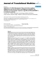
Fig. 1 Schematic diagram of an all-Si quantum dot super lattice
tandem solar cell [2]
Fig. 2 Normalised photoluminescence for Si QDs of various sizes in
SiO
2
matrix [1]
Fig. 3 Schematic diagram of a single-junction Si QD solar cell on
quartz substrate. The total thickness of the p–n junction diode is
420 nm. The thickness of the quartz substrate is 1 mm
Nanoscale Res Lett (2010) 5:1762–1767 1763
123
used to recover shunted polycrystalline thin-film solar cells
[12]. This mild chemical etch gradually removes the
shunting paths due to the reaction between Al and H
3
PO
4
acid. Measurement shows that the solar cell is no longer
shunted after the etching (Fig. 5b).
Effects of Nitrogen Gas Anneal and Forming Gas
Anneal
Dark and Illuminated I–V Characteristics
Another sample metallised with the aligned photo-lithog-
raphy method was subjected to an initial N
2
anneal at
250°C followed by three consecutive forming gas anneals
(250, 300 and 350°C). The duration of each annealing step
was 20 min. Dark and illuminated (1-sun) I–V data were
measured before and after each annealing step.
The dark currents in Figs. 5b and 6a are very different
due to the fact that these two devices are metallised in
different ways and have different contact geometry. The
contacts in the former (sample in Fig. 5b) are made by self-
aligned lithography technique which makes the lateral
distance between the base and emitter electrodes very small
(\5 lm) but easier to be shunted. On the other hand, the
latter aligned lithography approach (sample in Fig. 6a)
utilises two separate lithography masks, creating a larger
-4.00E-03
-3.00E-03
-2.00E-03
-1.00E-03
0.00E+00
1.00E-03
2.00E-03
3.00E-03
4.00E-03
-1.5 -1 -0.5 0 0.5 1 1.5
Voltage (V)
Current (A)
as fabricated
post FG anneal
Flat regions exceed limit
of current measurement
(b)
(a)
Fig. 4 a Schematic diagram of a Si QD cell with localised Al shunts.
b The corresponding dark I–V curves measured on the shunted cell
before and after the forming gas anneal
-5.00E-05
0.00E+00
5.00E-05
1.00E-04
1.50E-04
2.00E-04
2.50E-04
3.00E-04
3.50E-04
-1.5 -1 -0.5 0 0.5 1 1.5
Voltage (V)
Current(A)
after acid etching
(a)
(b)
Fig. 5 a Schematic diagram of the same cell as in Fig. 4 after H
3
PO
4
etching. Local Al shunts are removed. b The corresponding dark
I–V curve showing rectifying behaviour and a large shunt resistance
(R
sh
= 2 9 10
5
X)
Dark I-V
-1.00E-06
0.00E+00
1.00E-06
2.00E-06
3.00E-06
4.00E-06
5.00E-06
6.00E-06
7.00E-06
8.00E-06
-1.5 -1 -0.5 0 0.5 1 1.5
Voltage (V)
Currrent (A)
as fabricated
250C N2
250C FG
300C FG
350C FG
0.0E+00
1.0E+05
2.0E+05
3.0E+05
4.0E+05
5.0E+05
6.0E+05
as dep
250C N2
250C FG 300C FG 350C FG
Rs (ohms)
0.0E+00
5.0E+06
1.0E+07
1.5E+07
2.0E+07
2.5E+07
3.0E+07
Rsh (ohms)
Rs
Rsh
(a)
(b)
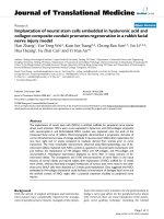
Fig. 6 a Evolution of the dark I–V characteristics of the measured
cell following initial nitrogen (250°C) and consecutive forming gas
anneals (250–350°C). b R
s
and R
sh
extracted from the dark I–V curves
as a function of annealing steps
1764 Nanoscale Res Lett (2010) 5:1762–1767
123
separation (*50 lm) between the base and emitter metal
contacts. Given that the resistance of the semiconductor
material is very high (as shown in Fig. 8), a larger lateral
contact separation makes the overall resistance of the
device substantially larger, resulting in a current decrease
of two orders of magnitude.
It has been noted that a N
2
gas anneal at 250°C has a
very limited influence on the I–V characteristics, while a
forming gas anneal at the same temperature is able to alter
the electrical properties (Fig. 6). With increasing forming
gas annealing temperature, there is a clear change in both
dark and light I–V curves. Information about the para-
sitic resistances (R
s
and R
sh
) is extracted from the dark
I–V curve. V
oc
and I
sc
are obtained from the light I–V data.
Details about the calculation of R
s
are discussed in later
sections.
The test solar cell with an initial open circuit voltage of
350 mV produces a V
oc
of 410 mV after the 350°C forming
gas anneal step (Fig. 7). The performance of the cell is
heavily limited by the series resistance, although the
magnitude of the series resistance has been reduced by
more than three times after annealing. The shunt resistance
has also decreased which might have a detrimental effect.
However, this effect is very small as R
sh
of the cell is in the
order of 1 MX.cm
2
. The short circuit current increases by a
factor of three due to the decrease of R
s
.
Contact and Sheet Resistances
To identify the origin of the large series resistance, a cir-
cular transfer length measurement (CTLM) [13] contact
was applied photolithographically to the n-type material
and measurements were carried out before and after each
annealing step. The measurement is able to extract contact
(R
c
) resistance of the bottom electrode and sheet (R
sheet
)
resistance of the n-type layer (Fig. 8).
It can be seen from the data that the 250°CN
2
gas
anneal has a negative impact on the cell’s contact resis-
tance, while the forming gas anneals improve the contact.
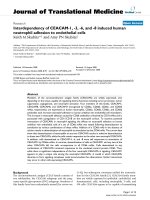
The change of sheet resistance is negligibly small when
annealed in N
2
ambient. However, annealing in forming
gas is able to reduce R
sheet
by approximately three times.
The contact resistance is small in comparison with the
semiconductor sheet resistance, as shown in Fig. 8.
Therefore, the reduction of series resistance is largely due
to the reduction of the material’s resistivity.
The implication of the results is that the H
2
in the
forming gas is responsible for the improvement of the cell
material. Hydrogen atoms are able to passivate the inter-
faces of the Si nanocrystals [14] and hence to reduce trap
density and facilitate better carrier transport.
Extraction of Series Resistance and Apparent Ideality
Factor (n)
Special attention has been paid to the analysis of the series
resistance (R
s
) of the cell. Instead of simply calculating the
slope of the dark I–V curve at the high voltage region, R
s
is
obtained according to the following.
In a general solar cell circuit model, the total voltage
across the terminals (V) equals the voltage across the
diode (V
D
) plus the voltage across the series resistance
(V
Rs
).
V ¼ V
D
þ V
Rs
ð1Þ
By rearranging the ideal diode equation [15]:
Light I-V
-3.3E-06
-2.3E-06
-1.3E-06
-3.0E-07
0 100 200 300 400
Voltage (mV)
Current (A)
as fabricated
250C N2
250C FG
350C FG
340.00
350.00
360.00
370.00
380.00
390.00
400.00
410.00
420.00
as dep 250C N2 250C FG 300C FG 350C FG
Voc (mV)
0.00E+00
7.00E-07
1.40E-06
2.10E-06
2.80E-06
3.50E-06
4.20E-06
4.90E-06
5.60E-06
Isc (A)
Voc
Isc
(b)
(a)
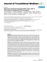
Fig. 7 a The 1-sun light I–V characteristics of the cell. b V
oc
and I
sc
extracted from the light I–V curves as a function of annealing
conditions
0.0E+00
5.0E+05
1.0E+06
1.5E+06
2.0E+06
2.5E+06
3.0E+06
as dep 250C N2 250C FG 300C FG 350C FG
Rc (ohms)
0.0E+00
8.0E+07
1.6E+08
2.4E+08
3.2E+08
4.0E+08
4.8E+08
Rsheet (ohms/sq)
Rc
Rsheet
Fig. 8 Contact (R
c
) and sheet (R
sheet
) resistances measured by CTLM
Nanoscale Res Lett (2010) 5:1762–1767 1765
123
I ¼ I
0
exp
qV
D
nkT
À 1
!
ð2Þ
and for V
D
[[nkT/q, it can be shown that
V
D
ffi
nkT
q
ln
I
I
0
ð3Þ
Substituting Eq. (3) into Eq. (1), yields
V ¼
nkT
q
ln
I
I
0
þ IR
s
ð4Þ
Differentiating V with respect to I,
dV
dI
¼
nkT
qI
þ R
s
ð5Þ
To obtain R
s
from the dark I–V data, it is convenient to plot
dV/dI against 1/I (See Eq.(5)). The plot appears to be a
linear relationship. The intercept of the line with the y-axis
gives R
s
(R
s
results are shown in Fig. 6b), while the slope of
the line equals to nkT/q. Thus, the ideality factor n = slope/
V
T
, where V
T
= kT/q is the thermal voltage.
The ideality factor (n) extracted for the cells investigated
in this work is found to be in the range 2–4 (Fig. 9), with no
obvious explanation as to why n should be greater than 2.
This may be because the conventional circuit model for a
solar cell, which accounts for current flow in only one
dimension, is insufficient for modelling a thin-film diode
with high base or emitter resistance. An improved circuit
model incorporating current crowding effects should be
used to describe this behaviour [6].
Conclusions
In this work, we have fabricated single-junction Si QD
solar cells on quartz substrates, as an important step to
realise an ‘all-silicon’ tandem solar cell.
The impacts of post-metallisation treatments such as
phosphoric acid (H
3
PO
4
) etching, nitrogen (N
2
) gas anneal
and forming gas (Ar: H
2
) anneal on the cells’ electrical and
photovoltaic properties have been studied. The Si QD solar
cells investigated in this work have achieved an open cir-
cuit voltage of 410 mV after various processes.
Parameters extracted from dark I–V, light I–V and cir-
cular transfer length measurement (CTLM) suggest that the
performance of the solar cell is strongly limited by poor
carrier transport. This limiting factor can be partly elimi-
nated by forming gas annealing.
Other possible solutions include reduction of the barrier
height and thickness of the quantum mechanical tunnelling
barrier, modification of the composition of the cell’s absor-
ber material, improved Si QD growth, an improved device
structure such asusing a transparent conducting contact (e.g.
ITO) or a conductive substrate to avoid current crowding.
Acknowledgments The authors gratefully thank all members of the
Third Generation Group at the ARC Photovoltaics Centre of Excel-
lence for their contributions to this project. This work is supported by
the Australian Research Council (ARC) via its Centers of Excellence
Scheme. The authors also acknowledge the support of the Global
Climate and Energy Project (GCEP), administered by Stanford Uni-
versity, for helping to fund this work.
Open Access This article is distributed under the terms of the
Creative Commons Attribution Noncommercial License which per-
mits any noncommercial use, distribution, and reproduction in any
medium, provided the original author(s) and source are credited.
References
1. M.A. Green, G.Conibeer, E C. Cho, D. Konig, S.J. Huang,
D.Song, G. Scardera, Y H. Cho, X.J. Hao, T. Fangsuwannarak,
S.W. Park, I. Perez-Wurfl, Y. Huang, S. Cheng, E. Pink, D.
Bellet, E. Bellet-Amalric, T. Puzzer, Progress with silicon-based
tandem cells using silicon quantum dots in a dielectric matrix. in
Proceedings 22nd EU PVSEC, Milan, Italy, Sept 2007
2. M.A. Green, G. Conibeer, D. Konig, E.C. Cho, D. Song, Y. Cho,
T. Fangsuwannarak, Y. Huang, G. Scardera, E. Pink, S. Huang,
C. Jiang, T. Trupke, R. Corkish, T. Puzzer, Progress with all-
silicon tandem cells based on silicon quantum dots in a dielectric
matrix. Proceedings 21st EU PVSEC, Dresden, Sept 2006
3. M. Zacharias, J. Heitmann, R. Scholz, U. Kahler, M. Schmidt,
J. Blasing, Appl. Phys. Lett. 80, 661 (2002)
4. Y.Z. Xie, V.P. Kunets, Z.M. Wang, V. Dorogan, Y.I. Mazur,
J. Wu, G.J. Salamo, Nano-Micro Lett. 1, 1–3 (2009)
5. E.C. Cho, S. Park, X. Hao, D. Song, G. Conibeer, S C. Park,
M.A. Green, Nanotechnology 19, 245201 (2008)
6. I. Perez-Wurfl, X. Hao, A. Gentle, D H. Kim, G. Conibeer, M.A.
Green, Appl. Phys. Lett. 95, 153506 (2009)
7. X. Hao, I. Perez-Wurfl, G. Conibeer, M. A. Green. in Proceedings
PVSEC 19, Korea, Nov 2009
8. M.A. Green, K. Emery, Y. Hishikawa, W. Warta, Prog. Photo-
volt: Res. Appl. 17, 320 (2009)
9. E.C. Cho, X.J. Hao, S.W. Park, D. Song, S. Huang, Y H. Cho, G.
Conibeer, M.A. Green, Toward silicon quantum dot junction to
realize all-silicon tandem solar cells. Proceedings 22nd EU
PVSEC, Milan, Italy, Sept 2007
10. X.J. Hao, E C. Cho, C. Flynn, Y.S. Shen, G. Conibeer, M.A.
Green, Nanotechnology 19, 424019 (2008)
1
1.5
2
2.5
3
3.5
4
0.25 0.35 0.45 0.55
Diode voltage (V)
Local ideality factor (n)
as fabricated
250C N2
250C FG
300C FG
350C FG
Fig. 9 Ideality factor n calculated from the I–V curves
1766 Nanoscale Res Lett (2010) 5:1762–1767
123
11. X.J. Hao, E C. Cho, G. Scardera, Y.S. Shen, E. Bellet-Amalric,
D. Bellet, G. Conibeer, M.A. Green, Sol. Energy Mater. Sol.
Cells 93, 1524 (2009)
12. D. Song, T.M. Walsh, A.G. Aberle, Monolithically integrated
polycrystalline silicon thin-film mini-modules on glass. in Pro-
ceedings 4th world conference on photovoltaic energy conver-
sion, pp. 2094–2097, May 2006
13. G.K. Reeves, Solid State Electron. 23, 487 (1980)
14. S. Godefroo, M. Hayne, M. Jivanescu, A. Stesmans, M. Zacha-
rias, O.I. Lebedev, G. Van Tendeloo, V.V. Moshchalkov, Nat.
Nanotech. 3, 174 (2008)
15. M.A. Green, Solar Cells: Operating Principles, Technology and
System Applications (UNSW, Sydney, 1992)
Nanoscale Res Lett (2010) 5:1762–1767 1767
123