Báo cáo hóa học: " Research Article Adaptive Channel-Tracking Method and Equalization for MC-CDMA Systems over Rapidly Fading Channel under Colored Noise" doc
Bạn đang xem bản rút gọn của tài liệu. Xem và tải ngay bản đầy đủ của tài liệu tại đây (752.94 KB, 12 trang )
Hindawi Publishing Corporation
EURASIP Journal on Advances in Signal Processing
Volume 2010, Article ID 871650, 12 pages
doi:10.1155/2010/871650
Research Article
Adaptive Channel-Tracking Method and
Equalization for MC-CDMA Systems over Rapidly Fading
Channel under Colored Noise
Chang-Yi Yang
1
and Bor-Sen Chen
2
1
Department of Computer Science and Information Engineering, National Penghu University, Penghu 88046, Taiwan
2
Department of Electrical Engineer ing, National Tsing-Hua University, Hsin-chu 300, Taiwan
Correspondence should be addressed to Chang-Yi Yang,
Received 22 October 2009; Revised 30 June 2010; Accepted 13 July 2010
Academic Editor: Cihan Tepedelenlio
ˇ
glu
Copyright © 2010 C Y. Yang and B S. Chen. This is an open access article distributed under the Creative Commons Attribution
License, which permits unrestricted use, distribution, and reproduction in any medium, provided the original work is properly
cited.
A recursive maximum-likelihood (RML) algorithm for channel estimation under rapidly fading channel and colored noise in
a multicarrier code-division multiple-access (MC-CDMA) system is proposed in this paper. A moving-average model with
exogenous input (MAX) is given to describe the transmission channel and colored noise. Based on the pseudoregression method,
the proposed RML algorithm can simultaneously estimate the parameters of channel and colored noise. Following the estimation
results, these parameters can be used to enhance the minimum mean-square error (MMSE) equalizer. Considering high-speed
mobile stations, a one-step linear trend predictor is added to improve symbol detection. Simulation results indicate that the
proposed RML estimator can track the channel more precisely than the conventional estimator. Meanwhile, the performance
of the proposed enhanced MMSE equalizer is robust to the rapidly Rayleigh fading channel under colored noise in the MC-CDMA
systems.
1. Introduction
The direct-sequence code-division multiple-access (DS-
CDMA) technique has already been successfully imple-
mented for third generation (3G) mobile communication
systems [1–3]. Its utilization of channel bandwidth is effi-
cient. Orthogonal frequency division multiplexing (OFDM)
is a parallel transmission technique and has been adopted
in IEEE802.16 [4, 5]. It can overcome the delay spread and
spectrum efficiency in wireless communication systems. The
idea of integrating the merits of both OFDM and CDMA
schemes, known as multicarrier-CDMA (MC-CDMA), has
attracted significant research interest recently. The MC-
CDMA system is a candidate technique for the next gener-
ation mobile communication system.
The MC-CDMA system divides the available bandwidth
into a large number of narrow subchannels [6–8]and
spreads each data symbol in the frequency domain by
transmitting all the chips of a spread symbol at the same
time, but in different orthogonal subchannels. One of the
properties of multicarrier transmission is that the channel
gain of each subchannel is different from the others. Since
the MC-CDMA systems spread transmitted symbols in
a nonflat fading channel, the inner product of different
spreading codes will no longer be zero. This leads to the
loss of orthogonality between different users. The multiple
access interference (MAI) is introduced and the performance
will be severely degraded in this situation. In order to
preserve the orthogonality between different users, channel
impairment should be estimated precisely and equalized
efficiently. Earlier works [9–11] for MC-CDMA detectors
made the assumption that the channel is perfectly known
at the receiver. Recently, the impact of channel-estimation
errors on the performance of MC-CDMA detectors has
attracted much interest, and different approaches have been
adopted for channel estimation and tracking. The pilot-
symbol-aided channel-estimation methods in both time and
frequency domains have been proposed [12–14], where the
2 EURASIP Journal on Advances in Signal Processing
estimated channel coefficients are then obtained through
the two-dimensional (2D) linear filtering. Other approaches
[15, 16] consider an explicit channel estimation based on
channel sounding in which a “train of pulses” spaced by the
maximum delay spread of the channel is transmitted instead.
A multiple channel model, which includes several possible
channel models based on the different ranges of Doppler
frequencies (or mobile velocities), is constructed to treat the
time-varying fading channel [17]. In addition, a decision-
directed channel estimation in the frequency domain using
Kalman-based filter has been proposed [18].
Although the MC-CDMA scheme is superior to noise
and interference suppression, some papers [19, 20] have indi-
cated that the narrowband interference (NBI) could affect its
performance. The bandwidth of NBI does not exceed one
subchannel. NBI is caused by intended jamming and some
narrowband services. It can be considered as one kind of
colored noise which has nonflat power spectral density and
hasbeenanalyzedin[21, 22]. NBI can be eliminated by
notch filters in the CDMA systems [23–27]. The channel
parameters are then estimated after despreading. But in the
MC-CDMA systems, the objective of channel estimation is
to make the gain of each subchannel equal for despreading.
That is, the channel estimation and equalization should be
done before despreading. Therefore, the notch filter will
destruct the orthogonality and is not feasible for MC-
CDMA systems. The frequency-domain channel-estimation
methods in the MC-CDMA systems will fail if the channel
contains colored noise. It is because the colored noise can
be considered as a white noise in each subchannel but
with different power. When those pilot subcarriers suffer
from noise with large power, the estimation results are no
longer reliable and the performance degrades due to the
loss of orthogonality between different users. Conventional
estimation methods [28] are also unsuitable for channel
estimation under colored noise because they will lead to a
biased estimate due to the dependence between the residue
and regression signal.
A channel-estimation algorithm for MC-CDMA systems
undercolorednoiseisproposedinthispaper.Itisderived
based on the recursive maximum likelihood (RML) algo-
rithm. It can jointly estimate the parameters of channel
and colored noise in the time domain. A moving-average
model with exogenous input (MAX) is used to describe
the dynamics of channel and colored noise (or NBI). The
colored noise is modeled as a moving-average (MA) process
with a driving white noise. Since the driving white noise
is unavailable, it is difficult to estimate the parameters of
colored noise in the real time for precise channel estimation.
The proposed method uses the estimated residue instead
of the driving white noise to overcome this problem. After
the channel parameters are estimated, they are fed to the
minimum mean-square error (MMSE) detector to improve
the performance of equalization.
The most important contribution of the proposed
method is that the channel impulse response (CIR), the
parameters of colored noise, and the power of the driving
noise in the MC-CDMA systems can be simultaneously
estimated in real time. Since the proposed method works
in the time domain, it can significantly reduce the number
of the estimated parameters compared with the methods
in the frequency domain. For example, the number of the
estimation algorithms in [18], which works in the frequency
domain, should be 512 if there are 512 subchannels. Its
computation algorithm is more complicated. But only
an algorithm is needed for the channel estimation, no
matter how many subchannels the MC-CDMA system has.
However, the channel-parameter estimation in the time
domain is easily deteriorated by colored noise. The proposed
RML algorithm can overcome this problem with a simple
scheme. Based on the estimation results, an enhanced
MMSE equalizer is employed for symbol detection. The
performance is demonstrated by the computer simulations.
This paper is organized as follows. In Section 2, the MC-
CDMA system is described. The proposed RML channel
estimator is introduced in Section 3. The decision-directed
channel-tracking process and the design of enhanced MMSE
detector for the proposed method are presented in Section 4.
The computer simulations of the adaptive MC-CDMA
detector are presented and compared in Section 5,and
the conclusions are summarized in Section 6. In what
follows, A
T
denotes the transpose of A,andA
H
denotes the
Hermitian of A. denotes the circular convolution.
2. MC-CDMA Communication System
This section describes the models of the transmitter and
receiver in an MC-CDMA system with N
s
subchannels and
N
u
users. The nth multicarrier block symbol (duration T)
for user j is formed by taking μ symbols d
1
j
(n), , d
μ
j
(n)in
parallel, which are spread by the user’s spreading code c
j
with
length N. Thus, the μ spread symbols are placed into N
s
=
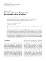
μN available subchannels. The transmitter’s block diagram is
shown in Figure 1. In the rest of this paper, for simplicity of
notation, we concentrate only on the case where each user
transmits one symbol (μ
= 1) in each MC-CDMA block
symbol. The transmitted symbol is simply represented as
d
j
(n)foruserj. Therefore, the total number of subchannels
is N
s
= N.
2.1. Model of Transmitter. The Walsh-Hadamard spread code
c
j
for user j with length N is
c
j
=
c
j
(0) c
j
(1) ··· c
j
(N −1)
T
,(1)
where c
j
(n) ∈{1/
√
N, −1/
√
N} and
c
T
i
c
j
=
⎧
⎨
⎩
1, if i = j,
0, otherwise.
(2)
The nth symbols with spread sequence of all N
u
users
transmitted on the mth subchannel can be written as
S
n
(
m
)
=
N
u
j=1
c
j
(
m
)
d
j
(
n
)
(3)
EURASIP Journal on Advances in Signal Processing 3
d
1
(n)
d
2
(n)
.
.
.
d
N
u
(n)
c
N
u
(0)
c
1
(0)
c
2
(0)
d
1
(n)
.
.
.
d
N
u
(n)
c
N
u
(N − 1)
c
1
(N − 1)
c
2
(N − 1)
d
1
(n)
d
2
(n)
d
N
u
(n)
.
.
.
Symbol
replication
N
S
n
(0)
S
n
(N − 1)
IDFT
size N
Add
cyclic
prefix
S
g
n
(0)
S
g
n
(1)
.
.
.
S
g
n
(N + G − 1)
P/S
S
g
n
(k)
DAC
Figure 1: Block diagram of the MC-CDMA transmitter.
for m = 0,1, , N − 1. The signal S
n
(m) is then translated
by the multicarrier modulation (i.e., IDFT), and the OFDM
symbol s
n
(k)isproducedasfollows(seeFigure 1):
s
n
(
k
)
=
1
√
N
N−1
m=0
S
n
(
m
)
e
j2πmk/N
(4)
for k
= 0, 1, , N − 1. A guard interval is inserted between
successive OFDM symbols to avoid the ISI effects by using
a cyclic prefix technique [29]. After the parallel-to-serial
conversion, the combination of the cyclic prefix with the
IDFT output sequence is given by
s
g
n
(
k
)
= s
n
(
k + N
− G
)
mod N
,(5)
for k
= 0,1, , N + G − 1, where the subscript n and
superscript g denote the nth signal block with a guard
interval. Thus, the total MC-CDMA symbol duration is (N +
G)T
c
,whereGT
c
is the guard interval duration and T
c
is the
sampling time. The value of GT
c
is larger or equal to the
maximum multipath delay spread τ
max
of the channel, and
is small in respect to T
s
= NT
c
(a useful OFDM symbol
duration) to limit the spectral efficiency loss.
2.2. Model of Receiver. In the downlink case, all users’
transmitting signals are synchronous and experience the
same Rayleigh fading channel. The received signal of the nth
MC-CDMA symbol is given by
y
g
n
(
k
)
=
L−1
l=0
s
g
n
(
k
− l
)
h
n
(
k, l
)
+ v
g
n
(
k
)
(6)
for k
= 0, 1, , N + G − 1, where h
n
(k, l)andv
g
n
(k)denote
the lth path sample of the complex time-varying fading
channel with length L and the additive colored noise at the
kth instant of the nth MC-CDMA block symbol, respectively.
For a high data-rate transmission, it is reasonably assumed
that the channel is time invariant during one MC-CDMA
block symbol interval T [18], that is, h
n
(0, l) = h
n
(1, l) =
··· =
h
n
(N + G − 1, l)forl = 0, 1, ,L − 1. The index k
of h
n
(k, l) would be ignored in this case and can be simply
rewritten as h
n
(l). However, channel variation during the
successive symbol intervals is allowed. After removing the
guard interval from (6), the received signal can be described
as
y
n
(
k
)
= y
g
n
(
k + G
)
= s
n
(
k
)
h
n
(
k
)
+ v
n
(
k
)
(7)
for k
= 0, 1, , N − 1. Since v
n
(k) is a colored noise, it can
be modeled by an MA process
v
n
(
k
)
= u
n
(
k
)
+
P
p=1
a
n
p
u
n
k − p
,
(8)
where u
n
(k) is a driving noise modeled as zero-mean
white-Gaussian process with variance σ
2
u
,anda
n
(p) is the
coefficient of the pth tap at the nth symbol period. The
parameters a
n
(p) can be set to 0 for p = 1, , P if the
4 EURASIP Journal on Advances in Signal Processing
additive noise is white. After passing through DFT, the
received signal on the mth subchannel Y
n
(m)is
Y
n
(
m
)
=
1
√
N
N−1
k=0
y
n
(
k
)
e
−j2πkm/N
=
1
√
N
N−1
k=0
[
s
n
(
k
)
h
n
(
k
)
+ u
n
(
k
)
a
n
(
k
)
]
e
−j2πkm/N
= S
n
(
m
)
H
n
(
m
)
+ U
n
(
m
)
A
n
(
m
)
,
(9)
where
H
n
(
m
)
=
N−1
l=0
h
n
(
l
)
e
−j2πlm/N
,
A
n
(
m
)
=
N−1
p=0
a
n
p
e
−j2πpm/N
,
(10)
a
n
(0) = 1, and U
n
(m) is the frequency-domain noise. The
covariance of U
n
(m) can be expressed as
Q
U
n
(
m
)
= E
U
n
(
m
)
U
H
n
(
m
)
=
Nσ
2
u
.
(11)
Because the term A
n
(m), due to colored noise, may be large
at some n and m, the frequency-domain pilot-aided channel
estimation for H
n
(m) is not reliable if the interference power
A
n
(m) is high at that subchannel. Therefore, it is not easy
to estimate channel H
n
(m) accurately from the received
signal Y
n
(m) in the frequency domain. Furthermore, if the
number of subchannels is large, many parameters need to be
estimated. An RML method is proposed to jointly estimate
the coefficients of channel and colored noise in (7)and(8)
by the time-domain method via a pseudoregression scheme
in the next section. An MMSE detector is designed based on
the estimated coefficients to compensate the effects of the
colored noise.
3. RML Channel Estimation in
the Training Mode
The proposed RML channel estimator is developed to
eliminate the effect of colored noise in this section. It works
in the time domain, that is, the channel is estimated before
DFT. Combining (7)and(8), the receiving signal y
n
(k)can
be expressed as
y
n
(
k
)
=
L−1
l=0
h
n
(
l
)
s
n
(
k
− l
)
+
P
p=1
a
n
(
l
)
u
n
(
k
− l
)
+ u
n
(
k
)
=
s
n
(
k
)
s
n
(
k
− 1
)
··· s
n
(
k
− L +1
)
⎡
⎢
⎢
⎢
⎢
⎣
h
n
(
0
)
h
n
(
1
)
.
.
.
h
n
(
L
− 1
)
⎤
⎥
⎥
⎥
⎥
⎦
+
u
n
(
k
− 1
)
··· u
n
(
k
− P
)
⎡
⎢
⎢
⎣
a
n
(
1
)
.
.
.
a
n
(
P
)
⎤
⎥
⎥
⎦
+ u
n
(
k
)
= s
T
k,n
h
n
+ u
T
k,n
a
n
+ u
n
(
k
)
= φ
H
k,n
θ
n
+ u
n
(
k
)
,
(12)
where
s
k,n
=
s
n
(k) s
n
(k − 1) ··· s
n
(k − L +1)
T
,
h
n
=
h
n
(0) h
n
(1) ··· h
n
(L −1)
T
,
u
k,n
=
u
n
(k − 1) u
n
(k − 2) ··· u
n
(k − P)
T
,
a
n
=
a
n
(1) a
n
(2) ··· a
n
(P)
T
,
φ
k,n
=
s
T
k,n
u
T
k,n
H
,
θ
n
=
h
T
n
a
T
n
T
,
a
n
(
0
)
= 1.
(13)
The description of the transmission system in (12) is called
an MAX model. It is a simple form of ARMAX model
[30]. Since the driving noise u
n
(k) is white, the covariance
matrix of the driving noise u
n
is Σ
u
n
= E[u
n
u
H
n
] =
σ
2
u
I and assumed to be unknown at the receiver, where
u
n
= [u
n
(0) ··· u
n
(N −1)]
T
.Theparametersθ should
be estimated in the colored noise case to obtain accurate
channel model, that is, the parameters of the channel model
and colored noise will be simultaneously estimated from
(12). However, the regression vector φ
k
contains noises
u
n
(k −1) ··· u
n
(k −P), which are unavailable and should
be replaced by pseudoregression vector in the sequel.
EURASIP Journal on Advances in Signal Processing 5
Formulation of a maximum-likelihood channel-estima-
tion problem involves the derivation of a likelihood function
L(θ),
L
n
(
θ
)
=
1
(
2π
)
N/2
det Σ
u
n
1/2
e
−(1/2)ε
H
n
(θ)Σ
−1
u
n
ε
n
(θ)
(14)
or the log-likelihood function
log L
n
(
θ
)
=−
1
2
log
(
2π
)
N
det Σ
u
n
−
1
2
ε
H
n
(
θ
)
Σ
−1
u
n
ε
n
(
θ
)
,
(15)
where
ε
n
(
θ
)
=
ε
0,n
(θ) ε
1,n
(θ) ··· ε
N−1,n
(θ)
T
,
ε
k,n
(
θ
)
= y
n
(
k
)
− φ
H
k,n
θ
n
.
(16)
Since the noise u
n
(k) is assumed as a zero-mean white-
Gaussian process and its variance σ
2
u
is unknown, (15)will
be replaced by the following log-likelihood function:
log L
n
θ, σ
2
u
=−
N
2
log
(
2π
)
−
N
2
log σ
2
u
−
1
2σ
2
u
N
−1
k=0
ε
k,n
(θ)
2
=−
N
2
log
(
2π
)
−
N
2
log σ
2
u
−
1
σ
2
u
V
N,n
(
θ
)
,
(17)
where
V
N,n
(
θ
)
=
1
2
N−1
k=0
ε
k,n
(θ)
2
=
1
2
ε
H
n
(
θ
)
ε
n
(
θ
)
=
1
2
y
n
− Φ
H
N,n
θ
n
H
y
n
− Φ
H
N,n
θ
n
,
Φ
N,n
=
φ
0,n
φ
1,n
··· φ
N−1,n
,
y
n
=
y
n
(0) y
n
(1) ··· y
n
(N −1)
T
.
(18)
The maximum-likelihood parameter estimation is to specify
θ and σ
2
u
to maximize the log-likelihood function in (17).
Using the least-square (LS) criteria, we get the following
estimation [28]:
θ
n
=
Φ
N,n
Φ
H
N,n
−1
Φ
N,n
y
n
,
σ
2
u
=
2
N
V
N,n
θ
n
.
(19)
Therefore, the maximum-likelihood parameter estimation
can be obtained. But there are still two problems. One is that
the noise components of φ
k
, that is, u
n
(k −1), , u
n
(k −P),
are unavailable. The other is that the parameter estimation
in (19) is in block form, which is not suitable for real-
time design in the MC-CDMA communication systems. A
recursive parameter estimation for (19)andanestimatefor
noise sequence u
n
(k − 1), , u
n
(k − P) are necessary in this
situation.
The recursive maximum likelihood (RML) method is
proposed via pseudolinear regression method in the follow-
ing equation [28]:
θ
k,n
=
θ
k−1,n
+
P
k−1,n
φ
k,n
λ + φ
H
k,n
P
k−1,n
φ
k,n
y
n
(
k
)
− φ
H
k,n
θ
k−1,n
,
P
k,n
=
1
λ
P
k−1,n
−
P
k−1,n
φ
k,n
φ
H
k,n
P
k−1,n
λ + φ
H
k,n
P
k−1,n
φ
k,n
(20)
which is the modified formulation of recursive least square
(RLS) method with a forgetting factor λ for improving the
rate of convergence in the time-varying channel. Originally,
the regression vector φ
k
used for recursive estimation is
[
s
n
(
k
)
s
n
(
k
− 1
)
··· s
n
(
k
− L +1
)
u
n
(k − 1) u
n
(k − 2) ··· u
n
(k − P)
]
H
.
(21)
It, of course, cannot be implemented since the driving
noise u
k,n
is unavailable by measurement. From (12), we get
u
n
(k) = y
n
(k) −φ
H
k,n
θ
n
. Therefore, the residue
k,n
,
k,n
= y
n
(
k
)
− φ
H
k,n
θ
k,n
, (22)
can be an estimate of u
n
(k). That means the noise com-
ponents of φ
k
can be substituted by their residues. The
regression vector φ
k,n
should be modified to the following at
each recursive step in (20),
φ
k,n
=
s
n
(
k
)
s
n
(
k
− 1
)
··· s
n
(
k
− L +1
)
k−1,n
k−2,n
···
k−P,n
H
.
(23)
The vector in (23) is called the pseudoregression vector
because noise component of the desired regression vector
is replaced by the estimated residues. The proposed RML
estimation algorithm is in the form of RLS algorithm but
is more powerful than the conventional RLS in the colored
noise case. Finally, the estimate of the variance of driving
noise is derived by using the residues in each recursion:
σ
2
u
=
1
N
N−1
k=0
k,n
2
. (24)
4. Adaptive Channel Tracking and Prediction in
the Tracking Mode
Since the wireless mobile channel is time-varying, the
channel model must be tracked continuously at the receiver
for the correct data detection. The proposed RML algorithm
in the previous section assumes the transmitted signal s
n
(k)
can be obtained. This is only true in the training mode,
but the transmitted signal is unknown for receiver in the
tracking mode. Therefore, the detected data will be fed to the
RML estimator to replace the transmitted signal for channel
estimation. This is the so-called decision-directed channel
estimation.
6 EURASIP Journal on Advances in Signal Processing
4.1. Decision-Directed Algorithm in the Tracking Mode.
In this subsection, an adaptive decision-directed channel-
estimation algorithm in the time domain is developed. The
conventional channel-estimation methods for multicarrier
transmission systems are equipped with pilots in the fre-
quency domain, which is spaced by coherence bandwidth.
When colored noise or NBI exists, the noise can be con-
sidered as white noise but with different powers in each
subchannel after DFT conversion at the receiver. As a result,
the pilot-symbol-aided channel-estimation methods [12, 13]
are no longer reliable because some pilot subcarriers suffer
from white noise with large power. Another drawback of
these methods is the occupancy of bandwidth, which is a
valuable resource for the service providers. Decision-directed
channel tracking is a solution to this problem since it does
not need any bandwidth and has a good performance in
the well-known channel [18]. But the parameters of channel
and colored noise are usually time varying. Therefore,
the proposed RML method is modified here for channel
tracking.
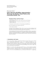
The data-flow diagram of the proposed decision-directed
algorithm is shown in Figure 2. The detected symbol
d
n
is used instead of the transmitted signal d
n
to identify
the channel (since the MMSE data detection scheme is
introduced in Section 4.3, it is assumed in this subsection
that
d
n
is available). Therefore, the parameters related to d
n
in the RML algorithm should be regenerated from
d
n
:
s
n
(
k
)
=
1
√
N
N−1
m=0
N
u
j=1
c
j
(
m
)
d
j
(
n
)
e
j2πmk/N
.
(25)
Thus, the regression vector in the channel-parameter-
tracking method is modified as
φ
k,n
=
s
n
(
k
)
s
n
(
k
− 1
)
··· s
n
(
k
− L +1
)
k−1,n
k−2,n
···
k−P,n
H
.
(26)
Based on the RML algorithm in (20), the following channel-
parameter-tracking scheme is proposed:
θ
k,n
=
θ
k−1,n
+
P
k−1,n
φ
k,n
λ +
φ
H
k,n
P
k−1,n
φ
k,n
y
n
(
k
)
−
φ
H
k,n
θ
k−1,n
,
P
k,n
=
1
λ
⎛
⎝
P
k−1,n
−
P
k−1,n
φ
k,n
φ
H
k,n
P
k−1,n
λ +
φ
H
k,n
P
k−1,n
φ
k,n
⎞
⎠
,
k,n
= y
n
(
k
)
−
φ
H
k,n
θ
k,n
,
(27)
and the variance of driving noise is calculated as
σ
2
u
=
1
N
N−1
k=0
k,n
2
.
(28)
The initial condition
θ
0,n
is equal to
θ
N,n−1
which is the latest
channel estimation of the previous MC-CDMA symbol and
N is the number of the recursion in one symbol duration. In
what follows,
θ
n
is equal to
θ
N,n−1
.
Since the transmitted signal s
n
(k) is unavailable for
receiver in the tracking mode, the regenerated signal
s
n
(k)
from the detected data
d
n
in (25) is directly replaced
for parameter tracking. In this way, the current channel-
parameter tracking is done after the current data detection.
However, the MMSE data detection needs to have the current
channel parameters. This is a delay problem of the decision-
directed channel-tracking scheme. A conventional decision-
directed scheme [18] adopts the previous estimates
θ
n−1
for the current MMSE data detection
d
n
, based on the
assumption that the channel variation is slow. However,
when the channel variation is fast, the previous estimates
will not be suitable for the current data detection. In order
to design MMSE detector at time n, the parameter
θ
n
must be predicted from the previous parameter-estimation
results to overcome the delay problem of the decision-
directed channel-tracking scheme. Thus, a linear trend
predictor is developed to predict one-step ahead channel
for improving the performance of data detection in the
following subsection.
4.2. Linear Trend Channel Predictor. When the mobile
station moves with high velocity and the symbol duration
is long, the channel will vary significantly from time n
− 1
to n. Since the decision-directed channel-tracking scheme is
used, the current channel parameters
θ
n
are predicted for the
current MMSE data detection. The simplest channel predic-
tor is formulated from the previous two estimated channel
parameters,
θ
n−1
and
θ
n−2
, with linear extrapolation. An m-
step linear trend predictor is formulated as
θ
n+m
=
θ
n
+ m · Δ
θ
, (29)
where
Δ
θ =
θ
n
−
θ
n−1
. (30)
In the case of m
= 1, that is, the one-step linear trend
predictor is given by
θ
n+1
=
θ
n
+ Δ
θ
n
= 2
θ
n
−
θ
n−1
(31)
or
θ
n
=
θ
n−1
+ Δ
θ
n−1
= 2
θ
n−1
−
θ
n−2
,
(32)
where
θ
n
=
h
n
(0) ···
h
n
(L −1) a
n
(1) ··· a
n
(P)
T
,
h
n
(
l
)
= 2
h
n−1
(
l
)
−
h
n−2
(
l
)
,
a
n
p
= 2a
n−1
p
− a
n−2
p
.
(33)
Performance of the MMSE detector can be improved with
the reliable channel-parameter prediction, and so the one-
step parameter prediction in (32) will be used for MMSE
detector with a decision-directed channel-tracking scheme in
the sequel.
EURASIP Journal on Advances in Signal Processing 7
ADC
y
g
n
(k)
S/P DFT
MMSE
detector
Decision-directed
channel tracking
Remove
cyclic
prefix
RML
channel
estimator
One-step
channel
predictor
Signal
regenerator
d
n
2
D
y
n
(k)
S
n
(k)
H
n
,
A
n
H
n+1
,
A
n+1
Figure 2: Block diagram of the decision-directed channel-tracking algorithm.
10
−3
10
−2
10
−1
10
0
Symbol error rate (SER)
0 5 10 15 20
SNR
MMSE per user detector (RML)
MMSE per user detector (RLS)
Channel is perfectly known (RML)
ZF detector using 2D pilots
Frequency domain Kalman filter
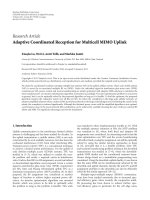
Figure 3: Symbol-error rate (SER) for different channel-tracking
methods in urban area.
4.3. Enhanced MMSE Equalizer for Sy mbol Detection. A
decision-directed channel-tracking algorithm based on the
proposed RML method and a simple one-step ahead channel
predictor have been developed to overcome the delay effect
of the decision-directed scheme under fast fading channel.
The MMSE detector using the proposed channel-tracking
algorithm is employed now. Before starting the design of
MMSE detector, it is necessary to express the received signal
Y
n
(m)in(9) with a matrix form by taking the N consecutive
subcarriers for the further development:
Y
n
= H
n
S
n
+ J
n
= H
n
Cd
n
+ A
n
U
n
,
(34)
where
Y
n
=
Y
n
(0) Y
n
(1) ··· Y
n
(N −1)
T
,
d
n
=
d
1
(n) d
2
(n) ··· d
N
u
(n)
T
,
H
n
= diag
H
n
(0) H
n
(1) ··· H
n
(N −1)
T
,
A
n
= diag
A
n
(0) A
n
(1) ··· A
n
(N −1)
T
,
U
n
=
U
n
(0) U
n
(1) ··· U
n
(N −1)
T
,
C =
c
1
c
2
··· c
N
u
.
(35)
The parameters predicted by the RML-based tracking
algorithm in association with the one-step linear trend
predictor are used for the MMSE detector. Since the RML-
based tracking algorithm can also estimate the parameters
of colored noise, the performance of MMSE detector could
be enhanced with this information. In consequence, the
proposed method will have better performance than the
conventional MMSE detectors with the use of white noise in
each subchannel.
To design the MMSE detector
w
j,n
for the jth user, the
following minimum mean-square error detection problem
must be solved:
w
j,n
= arg min
w
j,n
E
d
j
(n) −w
H
j,n
Y
n
2
. (36)
The solution of optimal detector with consideration of
colored noise in (36) is as follows:
w
j,n
= R
−1
YY
r
Yd
j
, (37)
8 EURASIP Journal on Advances in Signal Processing
where
R
YY
= E
Y
n
Y
H
n
=
H
n
CE
d
n
d
H
n
C
H
H
H
n
+ A
n
E
U
n
U
H
n
A
H
n
(38)
= σ
2
d
H
n
CC
H
H
H
n
+ Nσ
2
u
A
n
A
H
n
(39)
= σ
2
d
H
n
H
H
n
+ Nσ
2
u
A
n
A
H
n
, (40)
r
Yd
j
= E
Y
n
d
j
(
n
)
=
σ
2
d
H
n
Ce
j
, (41)
e
j
=
0 ··· 010··· 0
T
.
↑
jth
(42)
From (37)–(41), the optimal MMSE detector is necessary
to know the parameters of H
n
, A
n
, and the variance σ
2
u
of
the driving noise. These parameters can be obtained from the
proposed RML-based parameter-tracking algorithm in (27)-
(28). However, the current channel parameter is unavailable
before the current data detection and the previous estimates
are no longer suitable for the current data detection in
the fast fading channel. Therefore, the current channel is
predicted by feeding the previous two estimates of the
RML-based tracking algorithm for the one-step ahead linear
trend channel prediction in (31) (see Figure 2). Thus, the
parameters fed for the MMSE detection are obtained from
the one-step linear trend predictor. By DFT, the parameter
prediction is obtained as
H
n
(
m
)
=
L−1
l=0
h
n
(
l
)
e
−j2πlm/N
,
A
n
(
m
)
=
P
p=1
a
n
p
e
−j2πpm/N
,
(43)
where
h
n
(l)anda
n
(p) are obtained from the one-step linear
trend prediction in (32). Let us denote that
H
n
= diag
H
n
(
0
)
···
H
n
(
N
− 1
)
,
A
n
= diag
A
n
(
0
)
···
A
n
(
N
− 1
)
.
(44)
Therefore, the MMSE detector in (37) is reformulated as
w
j,n
=
σ
2
d
H
n
H
H
n
+ Nσ
2
u
A
n
A
H
n
−1
σ
2
d
H
n
Ce
j
.
(45)
The optimal MMSE detector is obtained by using the pro-
posed RML-based channel-tracking algorithm in association
with the one-step linear trend predictor as shown in Figure 2.
Finally, the merits of the proposal adaptive decision-directed
channel-estimation method are listed in Tab l e 1.
4.4. Performance Analysis for the Proposed Detection Method.
Performance of the symbol-detection method is evaluated
Table 1: Summarization of the merits of the proposed scheme.
Item no.
Improvement
1
CIR, parameters of the colored noise, and driving
noise estimated simultaneously
2
Working in the time-domain, reducing
complexity in comparison with the schemes in
frequency-domain
3
Without pilot symbol, saving bandwidth
4
Including one-step linear trend predictor, useful
for the fast-fading channel
in this subsection. From (37), the output of the MMSE
equalizer for user j is
d
j
(
n
)
= w
H
j,n
Y
n
= w
H
j,n
(
H
n
Cd
n
+ A
n
U
n
)
= w
H
j,n
H
n
Cd
n
+ w
H
j,n
A
n
U
n
.
(46)
Therefore, the average signal-to-noise ratio (SNR) of the
output for user j is
SNR
j, n
=
E
w
H
j,n
H
n
Cd
n
d
H
n
C
H
H
H
n
w
j,n
E
w
H
j,n
A
n
U
n
U
H
n
A
H
n
w
j,n
=
σ
2
d
E
w
H
j,n
H
n
H
H
n
w
j,n
Nσ
2
u
E
w
H
j,n
A
n
A
H
n
w
j,n
.
(47)
Finally, the decision output of the nth symbol for user j is the
following:
d
j
(
n
)
= sgn
d
j
(
n
)
, (48)
where sgn(
·) denotes the sign function of a decision choice.
For simplicity of analysis, only the case of BPSK will be
considered. Assuming that the total interference in (46)can
be approximated by a joint Gaussian distribution with zero
mean, the symbol detection error probability of user j for
the nth symbol can be approximated as [31]
P
e
j, n
=
Q
⎛
⎜
⎝
E
w
H
j,n
H
n
H
H
n
w
j,n
Nσ
2
u
E
w
H
j,n
A
n
A
H
n
w
j,n
⎞
⎟
⎠
, (49)
where Q(x)
= (1/
√
2π)
∞
x
e
−(t
2
/2)
dt for x ≥ 0.
5. Performance Evaluation by
Computer Simulation
Extensive computer simulations are given to demonstrate
the performance of the proposed RML channel estimator.
Before presenting the simulation results, the parameters
of the simulated MC-CDMA systems are described in the
following.
EURASIP Journal on Advances in Signal Processing 9
Table 2: Power delay profile in the typical urban area.
Delay (μs) Fractional power
0.0 0.189
0.2 0.379
0.5 0.239
1.6 0.095
2.3 0.061
5.0 0.037
5.1. Parameters of MC-CDMA Systems. Ta bl e 2 lists the
power delay profile in the urban area with the RMS delay
σ
τ
= 1 μs. If the coherent bandwidth is defined as the
bandwidth over which the frequency correlation function is
above 0.9, the coherence bandwidth B
c
is approximated to
1/50σ
τ
[32]. The central frequency f
c
is 1.8 GHz in the MC-
CDMA system. The total bandwidth BW is 1.024 MHz which
is divided into 512 subchannels. The subchannel spacing
is then Δ f
= 2 kHz. An additional 8μs guard interval
duration is used to provide protection from ISI due to
channel multipath delay spread. The length of the adopted
Walsh-Hadamard code is N
= 64 chips. Thus, the MC-
CDMA system can support the maximum number of active
users N
u
= 64. It is also assumed that the channel remains
approximately constant during one MC symbol period. In
the following simulations, the data modulation scheme is
QPSK.
5.2. Simulation Results. The following examples are sim-
ulated for 50 runs, and each run with 2000 MC-CDMA
symbols. The number of active user is 32. The forgetting
factor λ is 0.995. The initial value of P
k,n
is a unitary matrix.
In all cases, we normalize the gain of delay paths so that
L−1
l=0
E
|
h
n
(l)|
2
=
1.
(50)
Performance of the proposed method is compared with other
methods in several situations.
5.2.1. Slow Velocity. The velocity is 10 km/hr (the fading rate
f
d
T = 0.0086) in this simulation. The proposed method
without one-step predictor is used in this situation. The
symbol-error rate (SER) versus signal-to-noise ratio (SNR)
is illustrated in Figure 3. It can be seen that the SER of the
MMSE detector with perfect channel estimation is a lower
bound. In the 2D pilot-symbol-aided channel estimation
[12], the spaces between pilots in the time domain are
chosen according to coherence time T
c
≈ 9/16πf
d
[32]if
the coherent time is defined as the time over which the
correlation function is above 0.5. The spaces between pilots
in the frequency domain are chosen based on the coher-
ence bandwidth B
c
. A frequency-domain channel estimator
introduced in [18] is Kalman filter with a decision-directed
scheme. Since the frequency-domain channel estimator has
no immunity to colored noise, its performance is the worst
10
−3
10
−2
10
−1
10
0
10
1
Mean square error
0 5 10 15 20
SNR
RML channel estimator
2D interpolation
Conventional RLS
Frequency domain Kalman filter
Figure 4: MSE of different channel-tracking methods as v =
10 km/hr ( f
d
T = 0.0086) in urban area.
10
−3
10
−2
10
−1
10
0
Symbol error rate (SER)
0 5 10 15 20
SNR
MMSE per user detector (RML)
MMSE per user detector (RLS)
Channel is perfectly known (RML)
ZF detector using 2D pilots
Frequency domain Kalman filter
Figure 5: Symbol-error rate (SER) for different channel-tracking
methods as v
= 60 km/hr ( f
d
T = 0.0516) in urban area.
of the four methods. The conventional RLS can estimate the
channel parameters but not the parameters of the colored
noise. Therefore, it cannot achieve the MMSE detector
and its performance is worse than the proposed method.
The mean-square error (MSE) versus SNR is presented in
Figure 4. The proposed RML estimator has the lowest MSE,
and so its performance shown in Figure 3 is very close to the
performance with the perfectly known channel.
10 EURASIP Journal on Advances in Signal Processing
10
−3
10
−2
10
−1
10
0
10
1
Mean square error
0 5 10 15 20
SNR
One-step ahead predictor (RML)
2D interpolation
One-step ahead predictor (RLS)
Frequency domain Kalman filter
Figure 6: MSE of different channel-tracking methods as v =
60 km/hr ( f
d
T = 0.0516) in urban area.
5.2.2. High Velocity. When the mobile station moves with
high velocity, the channel will vary significantly in a symbol
duration. The conventional decision-directed methods will
fail in this situation because all of them feed the previous
estimates to the MMSE detector for current detection.
Based on the decision-directed RML-based channel-tracking
algorithm, we further design a one-step channel predictor
in Section 4 to overcome the delay problem. The SER and
MSE of channel tracking using different methods with and
without a one-step predictor are compared in Figures 5
and 6, in which the velocity 60 km/hr (f
d
T = 0.0516) is
considered for the design procedure. It is obvious that the
proposed RML-based tracking method in association with a
one-step channel predictor has the most accurate prediction
of the current channel for current data detection when the
channel is fast fading. Therefore, the SER of the proposed
method is the lowest. When the SNR is below 8dB, the
MSE and SER of the frequency-domain Kalman filter are
worst because it feeds the previous estimates to the MMSE
detector.
5.2.3. Diffe rent Velocities with Fixed SNR. The performances
of different estimation methods are compared when the
mobile station moves at different velocities with SNR
=
10 dB, as shown in Figure 7. The proposed method without
one-step predictor has the best performance with slow
velocity because the channel variation is slow. However,
when the mobile moves with high velocity, the proposed
method with a one-step channel predictor has the most
accurate prediction of current channel for the current MMSE
detection.
From these simulation results, the MMSE detector with
the proposed time-domain RML-based channel-tracking
10
−3
10
−2
10
−1
10
0
10
1
Mean square error
10 20 30 40 50 60 70 80 90 100
Velocity (km/hr)
One-step ahead predictor (RML)
Use previous estimate (RML)
2D interpolation
Conventional RLS
Frequency domain Kalman filter
Figure 7: MSE of channel tracking versus speed of user.
algorithm and the one-step channel prediction can signif-
icantly improve the performance of MC-CDMA under the
fast fading channel and colored noise. They are useful for
practical applications in the MC-CDMA communication
systems.
6. Conclusions
This work has presented a channel-estimation method and
an enhanced MMSE detector for an MC-CDMA system
under the rapidly fading channel and colored noise. The
proposed RML method can simultaneously estimate the
parameters of channel and colored noise, and the variance
of driving noise in the time domain with a simple scheme.
The MMSE detector will be enhanced by using the estimated
parameters. The proposed channel-estimation method can
work in the time domain because the parameters of col-
ored noise are estimated by using the residues generated
in the process of the recursive channel-estimation algo-
rithm. Another advantage is that the number of estimated
parameters in the time domain is less than that in the
frequency domain. Thus, the computational complexity
can be significantly reduced by decreasing the number
of estimated parameters. The decision-directed RML-based
channel-tracking algorithm can reduce occupancy of the
available bandwidth. Furthermore, a one-step linear trend
channel predictor is proposed to feed more accurate channel
parameters to MMSE detector for improving the current
data detection. The MSE of the proposed channel-estimation
scheme is improved and the SER is very close to the case
with the perfectly known channel parameters. The proposed
scheme provides better performance than the other methods
for MC-CDMA systems under the rapidly fading channel
EURASIP Journal on Advances in Signal Processing 11
and colored noise from simulation. It is because none of the
conventional channel-estimation methods can estimate the
parameters of colored noise in real time or they have other
drawbacks, that is, occupying of large bandwidth, inaccuracy
in the fast fading channel and under the colored noise, and
so forth. Therefore, the proposed decision-directed RML-
based channel-tracking method with a one-step linear trend
channel predictor is very useful for MC-CDMA systems over
rapidly Rayleigh fading channel with colored noise.
References
[1]A.J.Viterbi,Principle of Spread Spectrum Communications,
Addison-Wesley, Reading, Mass, USA, 1995.
[2] K. Tachikawa, W-CDMA Mobile Communications Systems,
John Wiley & Sons, New York, NY, USA, 2002.
[3] E. Dahlman, B. Gudmundson, M. Nilsson, and J. Sk
¨
old,
“UMTS/IMT-2000 based on wideband CDMA,” IEEE Com-
munications Magazine, vol. 36, no. 9, pp. 70–80, 1998.
[4] R. van Nee, G. Awater, M. Morikura, H. Takanashi, M.
Webster, and K. W. Halford, “New high-rate wireless LAN
standards,” IEEE Communications Magazine, vol. 37, no. 12,
pp. 82–88, 1999.
[5] IEEE Std. 802.16a, “Local and metropolitan area networks-
part 16, air interface for fixed broadband wireless access
systems,” 2003.
[6] N. Yee and J. P. Linnartz, “Wiener filtering of multi-carrier
CDMA in Rayleigh fading channel,” in Proceedings of the 5th
IEEE Internat ional Symposium on Personal, Indoor and Mobile
Radio Communications (PIMRC ’94), vol. 4, pp. 1344–1347,
The Hague, The Netherlands, September 1994.
[7] H. Xing and M. Renfors, “Performance evaluation of the
multi-carrier CDMA system with frequency domain equaliza-
tion,” in Proceedings of the IEEE Vehicular Technology Confer-
ence (VTC ’99), pp. 2362–2366, Amsterdam, The Netherlands,
September 1999.
[8] A. B. Djebbar, K. Abed-Meraim, and A. Djebbari, “Blind
and semi-blind equalization of downlink MC-CDMA system
exploiting guard interval redundancy and excess codes,” IEEE
Transactions on Communications, vol. 57, no. 1, pp. 156–163,
2009.
[9] T. Mueller, H. Rohling, and R. Gruenheid, “Comparison of
different detection algorithms for OFDM-CDMA in broad-
band Rayleigh fading,” in Proceedings of the 45th IEEE Vehic-
ular Technology Conference (VTC ’95), pp. 835–838, Chicago,
Ill, USA, July 1995.
[10] S. Kaiser, “Analytical performance evaluation of OFDM-
CDMA mobile radio systems,” in Proceedings of the 1st
European Personal and Mobile Communications Conference
(EPMCC ’95), pp. 215–220, Bologna, Italy, November 1995.
[11] D. N. Kalofonos and J. G. Proakis, “Performance of the
multistage detector for a MC-CDMA system in a Rayleigh
fading channel,” in Proceedings of IEEE Global Telecommuni-
catins Conference (GLOBECOM ’93), vol. 3, pp. 1784–1788,
Houston, Tex, USA, November-December 1993.
[12] S. Kaiser and P. Hoeher, “Performance of multi-carrier
CDMA systems with channel estimation in two dimensions,”
in Proceedings of the 8th IEEE International Symposium on
Personal, Indoor and Mobile Radio Communications (PIMRC
’97), pp. 115–119, Helsinki, Finland, September 1997.
[13] P. Hoeher, S. Kaiser, and P. Robertson, “Two-dimensional
pilot-symbol-aided channel estimation by Wiener filtering,” in
Proceedings of the IEEE International Conference on Acoustics,
Speech, and Signal Processing (ICASSP ’97), pp. 1845–1848,
Munich, Germany, April 1997.
[14] A. Nagate and T. Fujii, “A study on channel estimation
methods for time-domain spreading MC-CDMA systems,”
IEEE Transactions on Wireless Communications, vol. 7, no. 12,
pp. 5233–5237, 2008.
[15] S. Cacopardi, F. Frescura, F. Gatti, and G. Reali, “Channel
estimation and tracking of an indoor orthogonal multicarrier
DS-CDMA system using measured channel delay profiles,” in
Proceedings of the IEEE Vehicular Technology Conference (VTC
’96), pp. 1559–1563, Atlanta, Ga, USA, May 1996.
[16] S. Cacopardi, F. Frescura, and G. Reali, “Performance compar-
ison of multicarrier DS-SS radio access schemes for WLAN
using measured channel delay profiles,” in Proceedings of the
47th IEEE Vehicular Technology Conference (VTC ’97),pp.
1877–1881, Phoenix, Ariz, USA, May 1997.
[17] B S. Chen and J F. Liao, “Adaptive MC-CDMA multiple
channel estimation and tracking over time-varying multipath
fading channels,” IEEE Transactions on Wireless Communica-
tions, vol. 6, no. 6, pp. 2328–2337, 2007.
[18] D. N. Kalofonos, M. Stojanovic, and J. G. Proakis, “Perfor-
mance of adaptive MC-CDMA detectors in rapidly fading
rayleigh channels,” IEEE Transactions on Wireless Communi-
cations
, vol. 2, no. 2, pp. 229–239, 2003.
[19] J. Wang and H. Huang, “MC DS/SFH-CDMA systems for
overlay systems,” IEEE Transactions on Wireless Communica-
tions, vol. 1, no. 3, pp. 448–455, 2002.
[20] S. Kondo and L. B. Milstein, “Performance of mMulticarrier
DS CDNA systems,” IEEE Transactions on Communications,
vol. 44, no. 2, pp. 238–246, 1996.
[21] S. Akkarakaran and P. P. Vaidyanathan, “Results on principal
component filter banks: colored noise suppression and exis-
tence issues,” IEEE Transactions on Information Theory, vol. 47,
no. 3, pp. 1003–1020, 2001.
[22] M. Sternad and A. Ahlen, “The structure and design of
realizable decision feedback equalizers for IIR channels with
colored noise,” IEEE Transactions on Information Theory, vol.
36, no. 4, pp. 848–858, 1990.
[23] Y. Wang and L. B. Milstein, “Rejection of multiple narrow-
band interference in both BPSK and QPSK DS spread-
spectrum systems,” IEEE Transactions on Communications, vol.
36, no. 2, pp. 195–204, 1988.
[24] L. A. Rusch and H. V. Poor, “Narrowband interference
suppression in CDMA spread spectrum communications,”
IEEE Transactions on Communications, vol. 42, no. 2, pp. 1969–
1979, 1994.
[25] P R. Chang and J T. Hu, “Narrow-band interference sup-
pression in spread-spectrum CDMA communications using
pipelined recurrent neural networks,” IEEE Transactions on
Vehicular Technology, vol. 48, no. 2, pp. 467–477, 1999.
[26] W. Mao, H. Tsao, and F. Chang, “Anti-jamming solution of
GPS receiver using nonlinear adaptive predictor,” in Proceed-
ings of the14thInternational Technical Meeting of the Satellite
Division of the Institute of Navigation (ION GPS ’01), pp. 970–
974, Salt Lake City, Utah, USA, September 2001.
[27] H. Vincent Poor, “Active interference suppression in CDMA
overlay systems,” IEEE Journal on Selected Areas in Communi-
cations, vol. 19, no. 1, pp. 4–20, 2001.
[28] R. Johansson, System Modeling and Identification, Prentice-
Hall International, Englewood Cliffs, NJ, USA, 1993.
[29] J. E. Kim, S. H. Yoon, S. J. Kang, and C. E. Kang, “Multi-carrier
CDMA system using a code orthogonalising filter,” Electronics
Letters, vol. 34, no. 16, pp. 1557–1558, 1998.
12 EURASIP Journal on Advances in Signal Processing
[30] B K. Lee and B S. Chen, “Identification of fuzzy T-S ARMAX
models,” in Proceedings of the IEEE International Conference on
Fuzzy Systems, pp. 1019–1024, Budapest, Hungary, July 2004.
[31] J. G. Proakis, Digital Communications, McGraw-Hill, New
York, NY, USA, 4th edition, 2000.
[32] T. S. Rappaport, Wireless Communications: Principles and
Practice, Prentice Hall PTR, Upper Saddle River, NJ, USA,
2002.