Báo cáo hóa học: " Research Article An Unsupervised and Drift-Adaptive Spike Detection Algorithm Based on Hybrid Blind Beamforming" doc
Bạn đang xem bản rút gọn của tài liệu. Xem và tải ngay bản đầy đủ của tài liệu tại đây (979.63 KB, 13 trang )
Hindawi Publishing Corporation
EURASIP Journal on Advances in Signal Processing
Volume 2011, Article ID 696741, 13 pages
doi:10.1155/2011/696741
Research Article
An Unsupervised and Drift-Adaptive Spike Detection Algorithm
Based on Hybrid Blind Beamforming
Michal Natora and Klaus Obermayer
Institute for Software Engineering and Theoretical Computer Science, Faculty IV, Berlin Institute of Technology (TU Berlin),
Franklinstraße 28/29, 10623 Berlin, Germany
Correspondence should be addressed to Michal Natora,
Received 15 June 2010; Revised 25 October 2010; Accepted 16 November 2010
Academic Editor: Raviraj S. Adve
Copyright © 2011 M. Natora and K. Obermayer. This is an open access article distributed under the Creative Commons
Attribution License, which permits unrestricted use, distribution, and reproduction in any medium, provided the original work is
properly cited.
In the case of extracellular recordings, spike detection algorithms are necessary in order to retrieve information about neuronal
activity from the data. We present a new spike detection algorithm which is based on methods from the field of blind equalization
and beamforming and which is particularly adapted to the specific signal structure neuronal data exhibit. In contrast to existing
approaches, our method blindly estimates several waveforms directly from the data, selects automatically an appropriate detection
threshold, and is also able to track neurons by filter adaptation. The few parameters of the algorithm are biologically motivated,
thus, easy to set. We compare our method with current state-of-the-art spike detection algorithms and show that the proposed
method achieves favorable results. Realistically simulated data as well as data acquired from simultaneous intra/extracellular
recordings in rat slices are used as evaluation datasets.
1. Introduction
Extracellular recordings with electrodes constitute one of the
main techniques for acquiring data from the central nervous
system in order to study the neuronal code. Information
in this system is transmitted by short electric impulses,
called action potentials or, hereinafter, spikes. One of the
first processing stages of the recorded data, hence, consist
of identifying the occurrence times of these spikes. To this
end, various spike detection algorithms have been developed.
To give a structured overview of the recent development
in this field, we use a categorization scheme based on the
working principle of the methods. Note that although the
spike detection stage is one of the earliest, basically all
algorithms require already some preprocessing. This includes
a band pass filtering (usually between 0.5 kHz and 10 kHz)
and a zero mean normalization. In the following, we will still
refer to this kind of preprocessed data as “raw” data, since all
techniques rely on this initial step.
The first category of spike detection methods assumes
that the spikes exhibit a larger amplitude than noise fluctuations. Hence, spikes can be detected as data segments
which amplitude cross a certain threshold value. In [1]
three different variations of this detection paradigm were
described, including maximum, minimum, and absolute
value thresholding. Other related approaches rely on the
distance between the minimum and maximum value within
a certain time frame [2] or temporally hierarchical maximum
and minimum value thresholding [3].
The principle of the second category is based on the
transient nature of a spike; thus, spikes can be detected by
measuring some quantity describing the discontinuity of
data. An example is the nonlinear energy operator which
takes into account instantaneous energy and frequency, and
which was used for spike detection in [4]. Further adaptations of this method to neural data have been proposed in
[5, 6]. On the other hand, the approach in [7] considers
only the instantaneous energy difference while the proposed
method in [8] calculates the derivative of a temporally
accumulated energy. Also based on the first derivate of the
data are methods presented in [9, 10].
The algorithms falling into the third category rely on the
fact that spikes from a specific neuron exhibit a characteristic
waveform. The similarity between a data segment and
2
a specified waveform decides whether the considered data
segment contains a spike. When the actual waveform in
the data is unknown, a generic approach can be used. For
example in [11, 12] a biorthogonal, respectively, a coiflet
mother wavelets are used, since they exhibit a certain similarity in shape to waveforms found in some real recordings,
and a spike is said to be detected when a specific function
of wavelet coefficients exceeds a threshold value. In contrast,
unsupervised estimation (also called blind estimation) of the
waveform or blind equalization has been performed in [13]
by linear prediction, in [14] by automatic threshold setting,
or in [15, 16] by using the cepstrum of bispectrum.
The choice which algorithm should be used in an
application surely depends on the two important aspects
of computational complexity and detection performance.
Limited power and computing recourses, as encountered in
implantable circuits [17], restrict applicable algorithm to
have a very low computational load; hence most methods
from the first category, and some few from the second one
are used. When not limited by such constraints, it is favorable
with respect to the detection performance to use algorithms
belonging to the third category. This is motivated by the fact
that given the waveform and the noise covariance matrix,
the matched filter, or equivalently the minimum variance
distortionless response beamformer (MVDR), is the optimal
detector in case of Gaussian noise [18].
The aforementioned spike detection methods based on
blind equalization suffer from three main drawbacks. Firstly,
they construct only a single filter. In many experimental situations, however, spikes from more than one neuron, having
distinct waveforms, are present in the electrode recordings.
The single filter either captures just one waveform, meaning
that spikes from the other neurons will be detected poorly,
or the filter is an average filter which will have a suboptimal
response to spikes from all the neurons. This problem
aggravates that the more neurons are present, the more
the waveforms are distinct, which is especially the case in
multichannel recording devices, such as tetrodes [19].
Secondly, few methods offer an automatic threshold
selection mechanism, thus allowing for a truly unsupervised
operation. The available approaches [20–23] focus on the
case when spike detection is done by amplitude thresholding
(first category). For the above mentioned methods which rely
on blind equalization, none or only heuristic values are given
regarding the choice of an appropriate threshold.
Thirdly, the mentioned methods are nonadaptive. Once
a filter is calculated on a data segment in the time interval
[t, t + T], it is also applied to all subsequent data segments
at times τ > t + T. Particularly in acute recordings, the
shape of the waveform will change over time [24]; hence
the performance of the filter will be suboptimal if it is not
adapted. One could reestimate the template and recalculate
the filter after every time interval; however, this would
increase the computational load significantly, and tracking
of neurons would become difficult.
In this contribution, we propose a new spike detection algorithm which overcomes all those drawbacks. The
algorithm is derived by considering the spike detection
task as a blind equalization problem in a multiple-input,
EURASIP Journal on Advances in Signal Processing
SEA
Mode detection
Sparse deflation
If abortion criteria met
MVDR
calculation
Threshold
calculation
Adaptation
Filtering +
thresholding
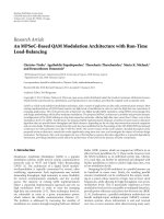
Figure 1: Schematic illustration of the proposed algorithm HBBSD.
The algorithm starts with the superexponential algorithm (SEA)
and iterates between SEA, Mode detection, and Sparse deflation
repetitively, until certain abortion criteria described in Section 2.5
are met. This iterative procedure allows to estimate blindly several
spike waveforms and the noise covariance matrix. Finally, the
MVDR filters and the corresponding thresholds are calculated.
Spike detection is done by thresholding the filter output and the
newly detected spikes are used to update the filters, allowing for
neuron tracking.
single-output system. The algorithm consists of a two-step
procedure. In the first step, an iterative algorithm based
on higher-order statistics, mode detection, and deflation
is used. This gives estimates of the spike templates and
the noise covariance matrix, from which in the next step,
the minimum variance distortionless response (MVDR)
beamformers are calculated, leading to an increased detection performance. This also allows to formulate a threshold selection algorithm as well as an effective adaptation
scheme (see Figure 1 for a graphical representation of
the whole algorithm). Because we use techniques from
both fields, that is, blind equalization and classical beamforming, in the context of spike detection, we call our
method hybrid blind beamforming for spike detection
(HBBSD).
A simplified version of the core algorithm and some
preliminary results were published in [25]. This contribution not only extends both in several ways but also
presents a significant amount of new algorithms and results.
Amongst others, the threshold calculation and the drift
adaptation are introduced, and the algorithm is tested on
many new datasets, including experimental data from rat
tissue.
The rest of the paper is organized as follows. In Section 2
the algorithm and all its individual steps are described.
The evaluation of its performance and comparison with
existing spike detection methods are presented in Section 3.
Conclusive remarks are given in Section 4. The notation used
throughout this paper is explained in Table 1.
EURASIP Journal on Advances in Signal Processing
3
Table 1: Bold lower case letters denote vectorial quantities whereas
bold upper case letters represent matrices. Superscripts refer to the
iteration index while subscripts refer to a group index.
Symbol
qi
qi (t)
qi
qi [t]
C, C
h(k)
Description
ith (true) waveform
vector entry at tth position
estimate of the ith waveform
time dependent waveform
true/estimated noise cov. matrix
SEA filter at iteration k
Reference
Section 2.1
Section 2.1
Section 2.4
Section 3.8
Sections 2.1 and 2.6
Section 2.2
2. Methods
2.1. Model of Recorded Data. In order to derive a wellmotivated algorithm avoiding heuristics as much as possible,
the recorded data have to be described by some signal model.
In the neuroscience community, it is widely accepted that
the data x recorded at an electrode can often be represented
as a linear sum of convolutions of the intrinsic spike trains
si with constant waveforms qi and colored Gaussian noise
n (having a noise covariance matrix C); see, for example,
[26, 27]. Explicitly, it is
M
x(t) =
i=1 τ
qi (τ)si (t − τ) + n(t),
(1)
where M is the number of neurons whose spikes are present
in the recordings. For the sake of clarity, we restricted the
model to single channel recordings, that is, electrodes, but
an extension to multichannel data as provided by tetrodes is
straightforward.
Since the goal of spike detection is to recover the spike
trains si from a linear time-invariant system without a priori
knowledge about the shape of the waveforms qi , this can
be viewed as a blind equalization problem (often also called
blind deconvolution, blind identification, or convolutive
blind source separation). An overview about this topic and a
survey of available methods dealing with such problems can
be found in [28].
Most often, M, the number of sources, will be larger
than the number of recording channels. In the model of a
single electrode as described in (1), the number of recording
channels is equal to one, in which case the generative system
is referred to as multiple-input, single-output. In general, it is
not possible to extract more sources than available recording
channels [28]. In the following, we make explicit use of the
unique properties of neural data, such as sparseness and
binary alphabet, to overcome this restriction partially.
2.2. Application of the Superexponential Algorithm. The
superexponential algorithm (SEA) developed in [29]
achieves blind equalization by applying a filter which is
calculated by use of higher-order cross cumulants. For
real-valued data, the filter h at iteration k + 1 is computed as
h(k+1) =
R−1 · d(k)
,
d(k) · R−1 · d(k)
(2)
where R is the data covariance matrix, that is, R(i, j) =
cov(x(t − i), x(t − j)), d(k) (n) = cum(y(k) (t) : p, x(t − n) :
1) denotes the cross-cumulant between p-times y(k) (t) and
x(t − n) (hence, the order of the statistics is p + 1), and
y(k) (t) = τ h(k) (τ)x(t + τ) being the filter output.
The algorithm works when the signals si are nonGaussian and when the qi are stable (stable in the sense
of robust against noise, not in the sense of stationary in
time). In the context of neural recordings, both requirements
are surely met. Firstly, the si represent the intrinsic spike
trains, thus taking values of either 0 or 1, and whose
probability density function follows most likely a sparse
Bernoulli distribution, or their interspike interval a Poisson
distribution. Secondly, the waveforms qi are finite impulse
response filters, and hence are stable. The SEA algorithm
is said to have reached convergence when the difference
between two consecutive iterations is small enough (see also
Section 3.3). For convenience, we call the filter obtained at
the last iteration simply h, instead of h(klast ) .
The choice of the SEA instead of other blind equalization
algorithms was motivated by several of its features. It is
shown that in the noise-free case, the algorithm converges
independently of the initial condition to the globally optimal
solution with a superexponential convergence rate [29].
Since it uses higher-order statistics, this property should
also hold approximatively when Gaussian noise is present,
as higher-order cumulants are zero for Gaussian signals.
Moreover, the algorithm is not gradient based like Bussgang
type algorithms; thus no step size selection is required, which
reduces the amount of parameter settings for the user.
For neural data, we chose the order of the cumulant to
be p = 2 or p = 3. In the former case, the vector d is
proportional to the skewness, a statistics which is well suited
for asymmetric signals such as the si [30]. For p = 3, this
makes the vector d proportional to the kurtosis, which is a
good statistics in the case of sparse data following a model as
in (1) [31]. These findings were also confirmed in [32].
2.3. Mode Detection in the SEA Filter Output. The SEA
computes a single filter on the basis of a vector d which
contains the statistics of all M waveforms. Nevertheless, as
it is most likely that the characteristics of the neurons will
be different with respect to signal-to-noise ratio, spiking
frequency, or shape of waveform, it is expected that the
filter will have various responses to the different neuronal
waveforms. The idea is to identify spikes which belong to a
single component and recalculate the filter using only these
spikes. The identification is done by a technique called mode
finding [33]. Firstly, only the local maxima, denoted by mi ,
of the filter output y within a certain range 2Ls + 1 are
extracted. Then, the probability density function pm of the
mi is estimated by a kernel density estimator, which in the
assumed case of Gaussian noise is favorable to be a Gaussian
kernel. The kernel bandwidth is chosen optimally depending
on the amount of data [34]. The function pm will exhibit
a high amplitude mode due to noise and possibly several
low amplitude modes caused by spikes; see Figure 2. (Due
to the large amount of noise samples, the kernel bandwidth
4
will be relatively small, which guarantees that the modes
caused by spikes will not be smoothed away.) Hence, the
second largest mode, denoted by b2 , is the prominent spike
mode, that is, caused by spikes to which the filter responded
the most, and which consequently should be extracted from
the data first (see also Section 2.3.3). All mi which have a
smaller distance to b2 than to any other spike mode, and
which are also larger than the first local minimum separating
the noise peak from the first spike mode, are considered to
belong to b2 ; see Figure 2. However, modes which are in
the range of ±2σnh around b2 are not regarded as separate
modes whereas σnh denotes the estimated standard deviation
of the noise in the filter output (of filter h) (see Section 2.3.1).
This is motivated by the fact that two Gaussian distributions
with identical standard deviation do not exhibit two separate
modes, unless their means are at least 2σnh apart [35].
This merging of modes is necessary in order to minimize
the number of spurious modes which do not represent an
individual component but are mere artifacts caused by the
kernel smoothing.
2.3.1. Estimation of the Filter Output Noise Variance. To
estimate σnh , first the mean μnh of the filter output noise is
estimated. If one can assume that the noise n is zero mean,
this step can be avoided, since then it immediately follows
that μnh = 0 as well. Otherwise, the probability density
function of y is estimated by a Gaussian kernel density
estimator as described in the previous section. Making again
use of the sparseness of the data, the mean μnh is found as the
global maximum of this probability density function.
As we expect that the response of filter h to spikes is larger
than μnh , we ignore all values of y which are above μnh , since
they are likely to contain spikes. Hence, σnh is solely estimated
on values of y which are smaller than μnh .
2.3.2. Gaussianity of the Modes. Strictly speaking, due to the
maximum operation, the mi do not follow a Gauss distribution anymore, but rather an extreme value distribution.
Nevertheless, a Gaussian kernel is used for density estimation
and the spike modes are assumed to be Gauss distributed
as well. This is justified by the fact that the spike modes
exhibit large amplitudes in the filter output, and thus their
maximum values are still almost Gauss distributed even after
a maximum operation.
2.3.3. Largest Spike Mode Finding. From the kernel density
of the mi , first a Gaussian distribution with mean μnh and
standard deviation σnh is subtracted (not shown in Figure 2).
This removes the noise contribution to modes and ensures
that the largest spike mode b2 is indeed the prominent
one.
Note that in [14] also a mode detection procedure was
applied. In contrast to our approach, it was done on a generic
filter output consisting of squaring and lowpass filtering.
Moreover, we merge modes based on their proximity in
order to find all spikes belonging to the largest spike mode,
whereas in [14] only the local minimum separating the noise
EURASIP Journal on Advances in Signal Processing
0.6
0.5
0.4
0.3
0.2
0.1
0
−2
−1
0
1
2
3
4
5
6
5.5
6
6.5
7
(a)
0.06
0.05
0.04
0.03
0.02
0.01
0
3
3.5
4
4.5
5
7.5
(b)
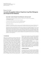
Figure 2: (a) Estimated probability density of the local maxima
mi . The spareness of the data is clearly exhibited by the large noise
peak (at around 1 on the x-axis) and some small spike peaks (at
around 4 and 5 on the x-axis). (b) Zoom in on the spike modes.
The circles indicate the local maxima of the modes that were found.
The mode at around 3.9 was identified as largest (b2 ), and the two
modes indicated by blue circles are discarded, as they are within
the range of ±2σnh . The estimated noise standard deviation σnh is
indicated by the thick bar. The green cross indicates the first local
minimum, separating the noise peak from the spike modes.
mode from the spike mode is found and a single template is
constructed.
2.4. Sparse Deflation. In classical algorithms designed
for multiple-input, multiple-output systems, sources are
extracted one by one using a technique called deflation [36].
As such, one single waveform q j is estimated via second
order statistics, the source s j is estimated via the convolution
of the corresponding filter h j with x, and the convolution
between q j and s j is subtracted from the data x. This classical
deflation procedure was developed by assuming that the
sources are continuous signals and that the waveforms have
to be known only up to a scalar factor. In contrast, the signals
EURASIP Journal on Advances in Signal Processing
5
representing the occurrences of spikes are discrete and sparse,
and, as will be shown in Section 2.6, the waveforms need to
be known without ambiguity.
Therefore, we propose an adapted deflation procedure
which we call sparse deflation, as it relies on the sparseness of
the data. At iteration j data segments x( j) i of length 2L f + 1
are cut out of x around the occurrence times tmi + tshift of
the local maxima mi , i = 1, . . . , K, which belong to mode b2 .
The shift tshift is determined so that the cut out data segments
have maximum total energy. Without this step, extraction
of different parts of the same waveform at several iterations
would be possible, as the SEA filter does not necessarily
respond maximally at the center of a waveform. Finally, the
waveform is estimated as the median of all data segments,
that is,
( j)
( j)
q j (t) = med x1 (t), . . . , xK (t)
t = −L f , . . . , L f ,
2.5. Abortion Criteria. The iteration loop (SEA, mode detection, sparse deflation) is terminated if at least one of the
following criteria is met.
(i) No spike mode can be identified in the filter output
anymore, or the number of spikes belonging to the
spike mode b2 is below a relative threshold min f .
(ii) A maximum number of iterations is reached.
If the loop abortion happens after the first iteration already,
the filter obtained by (2) is used for further spike detection
instead of the MVDR beamformers.
2.6. Calculation of the MVDR Beamformers. Once the iteration loop described in the previous sections is completed, the
final filters used for spike detection are calculated. Namely,
we use the MVDR beamformers which are given by [18]
C−1 · qi
,
qi · C−1 · qi
2.7. Filtering and Spike Detection. After calculating the
MVDR beamformers, the data are filtered with each of them,
and a spike is declared as detected when the filter output z
exceeds a certain threshold γ, that is,
z j (t) =
τ
=: (f
f j (τ)x(t + τ)
detection
if z j (t) ≥ γ j
(5)
x)(t).
(3)
where K is the total number of local maxima mi belonging
to mode b2 .(An even better performance could be achieved if
the data segments were first upsampled, aligned, averaged,
and then downsampled [27].) Instead of subtracting the
estimated contribution of source s j , the data segments x( j) i
are simply removed from the data. The reduced dataset
x \ x( j) i , i = 1, . . . , K, is now used as the starting point for
the next iteration of the algorithm. In particular, the steps
described in Sections 2.2–2.4 are repeated on the updated
data x \ x( j) i=1,...,K =: x. (The covariance matrix R and
cumulant vector d are computed on each remaining data
chunk separately and the final estimates are obtained as a
proportionally to the data chunk length weighted average.)
fi =
such that their response is one at the center of a waveform,
that is, fi · qi = 1.
The estimate of C is done after the last algorithm
iteration, as the deflated dataset x \ x( j =1,...,J) i=1,...,KJ contains
far less spikes than the original data x allowing for a more
accurate noise estimation.
(4)
where C is the estimate of the noise covariance matrix,
and qi denotes the vectorial representation of the ith estimated waveform, the individual entries being
qi (−T f ), . . . , qi (+T f ); (see (3)). (Note that other filters
could be used instead, for example, adapted to a real-time
detection task [37].) The MVDR beamformers are designed
2.8. Threshold Selection. The threshold for every filter is
selected individually such that the probability of detection
PD is maximal (probability of a true positive detection),
whereas the probability of false alarm PFA (probability of a
false positive detection) should be minimal. If one admits a
certain tolerance Δ in the arrival time estimation, meaning
that a spike is declared as correctly detected when the filter
output exceeds the threshold somewhere in the interval
[tspike − Δ, tspike + Δ], the probability of detection for filter
f j given threshold γ j is expressed as
PD j γ j = 1 −
Δ
τ =−Δ
PN j
fj
q j (τ) ,
(6)
√
where PN j (x) := 1/2 · (1 + erf((γ j − x)/ 2σ j )) with σ j :=
f j Cf j . Thus PN j (x|x=(f j q j )(τ) ) is the probability that the
waveform is not detected at time sample τ, whereas q j is
defined in Section 2.9. Similarly, the probability that a noise
segment of length 2Δ + 1 is falsely detected is given by
PFA j γ j = 1 − PN j (0)
2Δ+1
.
(7)
An optimal detector would always achieve a perfect performance of PD = 1 and PFA = 0; thus any detector
should have a performance as close as possible to the perfect
performance. The optimal threshold, hence, is selected
according to
⎧ ⎛ ⎞ ⎛
⎞ ⎫
⎪ 0
⎪
⎨
⎬
⎜PFA j γ j ⎟
γ j = argmin⎪ ⎝ ⎠ − ⎝
⎠ ⎪.
⎩ 1
⎭
γj
PD j γ j
(8)
This optimization problem can be solved efficiently as it
involves only a single parameter, namely, the threshold
γ j , which should lie in the interval [0, 1]. In practice, we
evaluate PFA j and PD j for all threshold values in [0, 1] with
a resolution of 0.0005, and select as optimal threshold the
one which minimizes (8).
When the thresholds are obtained by (8), it is assumed
that detecting a spike is equally important as avoiding a
false positive detection. However, with respect to subsequent
6
EURASIP Journal on Advances in Signal Processing
analysis for understanding the working principles of the
nervous system, it was shown that not detecting a spike has
more impact than declaring incorrectly a piece of noise as a
spike [38]. This particular characteristic of neural data could
be incorporated by introducing a weighting parameter in (8).
2.9. Adaptation to Changing Waveforms. In (1) we assumed
that the waveforms q j are constant in time, which is
approximatively true for short periods at the beginning of an
experiment. Due to tissue relaxation, however, the distance
between the electrode and the neurons changes, which leads
to altered recorded waveforms [24]. In [39] we proposed an
adaptation scheme for an estimated spatial waveform and
the corresponding filter. This method was especially designed
for sparse binary data such as neuronal data. Herein, we
shortly summarize this method and extend it to multiple,
temporal waveforms. In brief, after every time interval T,
each waveform is updated as the mean of the Kopt last data
chunks r of length 2L f + 1 which were detected as spikes, that
is,
qj =
1
Kopt j
(a)
(b)
(c)
(d)
Kmax
·
i=Kmax j −Kopt j +1
r j,i ,
(9)
where r j,i := x(t(i) − L f ), . . . , x(t(i) + L f )
such that
f j · r j,i ≥ γ j , and Kmax j denotes the maximum number of
found spikes by filter f j . If two or more filters detect the same
spike, the spike is assigned to one filter only, namely, to the
one which had a response closest to 1. The optimal number
of spikes for averaging is determined by
Kopt j = argmax M j (K) ,
K
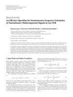
Figure 3: (a–c) Waveform templates obtained from extracellular
recordings in macaque and used for generation of artificial datasets.
(d) Waveform template obtained from simultaneous intra/extracellular recordings in rat tissue.
(10)
where M := PD j + (1 − PFA j ), and q j is estimated as the mean
waveform of the Q last detections of filter f j .
2.10. Implementation. The higher-order cross cumulants
were calculated by the use of the HOSA toolbox [40]. The
proposed algorithm was implemented in MATLAB version
7.6, but not optimized for maximum computational speed
yet. The code and a sample file will be made available at the
website />Regarding computational complexity, the most expensive
task is the computation of the cross cumulants during
the SEA algorithm. This computation, however, can be
parallelized, in the sense that every time shift can be
computed on a separate computing unit.
3. Performance Evaluation
3.1. Generation of Artificial Data. Artificial data were generated according to the model in (1). The waveforms
were constructed from sorted spikes obtained from acute
recordings in the prefrontal cortex of macaque monkeys and
had a length of about 0.9 millisecond; see Figures 3(a)–
3(c). Detailed information about the sorting method and
the experimental setup were described in [41, 42]. The spike
arrival times were simulated as independent homogeneous
Poisson processes with an enforced refractory period of 2
millisecond. The noiseless data were simulated at a sampling
frequency of 40 kHz and then downsampled to 10 kHz,
in order to include the phenomenon of sampling jitter
as encountered in real recordings. Gaussian noise with
an autocorrelation structure measured in real recordings
was simulated by an ARMA process and added to the
spike trains (see [42] for more details). Two types of
datasets were simulated, one containing activity from two
neurons, whereas the other one contained activity from three
neurons. A data snapshot from the latter type is shown in
Figure 4.
3.2. Performance Assessment. To allow for a better comparison, the most common definition of signal-to-noise ratio
(SNR) utilized in the neuroscience community (see, e.g.,
[12]) was used. Namely, the SNR of the i-th spike train is
defined as the ratio between the norm of the corresponding
waveform and the standard deviation of noise:
SNRi =
qi ∞
.
σn
(11)
The detection performance of an algorithm was investigated by means of receiver operator characteristic (ROC)
EURASIP Journal on Advances in Signal Processing
7
Amplitude
Amplitude
5
0
−5
6.47
6.48
6.49
6.5
6.51
Time in samples
6.52
6.53
6.54
×104
(a)
0.4
0.2
0
−0.2
−0.4
7800
7900
8000 8100 8200
Time in samples
8300
8400
8500
(b)
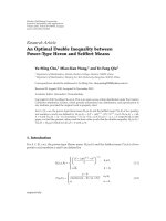
Figure 4: (a) Data chunk of simulated data with an SNR value of 3.0; that is, all inserted waveforms had an SNR of 3.0. The markers indicate
the occurrence times of the inserted spikes, whereas the templates shown in Figures 3(a)–3(c), were used. (b) Data chunk of experimental
data from simultaneous intra/extra-cellular recordings in rat tissue. The empirically determined SNR is 3.050 and the extracted waveform is
shown in Figure 3(d).
curves and the corresponding areas under the curves (AUCs),
similarly defined as in [14]. The ROC curves were calculated
by evaluating the relative number of true positive (TP) and
false positive detections (FP), given by
TP =
number of correct detections
,
number of inserted spikes
number of false detections
.
FP =
maximum number of possible false detections
(12)
A detection was classified as correct, if the detectors response
was within ±0.4 millisecond of the true spiking time, which
implied Δ = 2 in the parameter setting of the HBBSD
algorithm. Multiple detections within this time frame were
ignored. Consequently, there is a maximum number of
possible false positive detections a detector can produce in
a dataset of finite length. By the definition in (12), both
quantities TP and FP are bounded on the interval [0, 1].
3.3. Parameter Settings of HBBSD. In all subsequent simulations the following parameters were used in the HBBSD
algorithm: the SEA algorithm was said to have reached
convergence if h(k+1) − h(k) 2 ≤ 10−10 . The SEA algorithm
used higher-order statistics with p = 2 but switched
automatically to p = 3 if no convergence could be achieved
in the former case. The minimum firing frequency min f
was set to 5 Hz, the filter length was equal to 9 samples
(L f = Ls = 4), and the maximum number of 3 filters was
allowed. Here we would like to point out that, unlike in
some other methods, where the parameters are algorithm
specific and thus their value setting is not an obvious task, the
parameters of HBBSD are biologically motivated, allowing
for a reasonable choice of their values. For example, since
single channel data are analyzed, it is sound to assume that
action potentials from not more than 3 to 4 nearby neurons
will be recorded, justifying a maximum filter amount of 3.
The filter length can be chosen as the length of a spike,
which is most often in the range of 0.4 to 1.0 millisecond
[12]. Besides, there exist methods to estimate the filter length
even when no biologically motivated a priori knowledge is
available [32, 43]. Finally, it is unlikely that neurons in a task
relevant brain region will exhibit very low firing frequencies,
but, as a matter of fact, the parameter min f could be
dropped entirely from the algorithm structure.
The needed estimate of the waveform q j (see Section 2.9)
was obtained as the mean of the Q = 75 last detections. As
was demonstrated in [39], the choice of the value for Q is not
critical.
3.4. Competing Algorithms. In [25] we compared the performance of HBBSD with existing methods covering all
categories described in Section 1. It was demonstrated that,
in general, algorithms relying on waveform information
outperform methods which are solely based on amplitude
thresholding or transient detection. Finally, it was shown
that a wavelet-based method such as [12] might perform
poorly when the actual waveform is distinct from the used
mother wavelet, and we concluded that the best available
method at the time is the one presented in [15, 16]. This
method accomplishes blind equalization by cepstrum of
bispectrum calculation and hence will be abbreviated as CoB.
The parameters for this algorithm were set according to its
reference and adapted to the herein considered sampling
frequency and spike length. Additionally, we compared our
method to the classical, single iteration, superexponential
method, denoted by SEA.
3.5. Performance on Data with Two Waveforms. Ten independent simulations, each of 6 seconds in length, containing
activity from two neurons with the waveforms (a) and (b)
shown in Figure 3 were simulated. The spiking frequencies
were 15 Hz and 25 Hz, respectively.
In Figure 5 the results for all compared methods are
shown. (This evaluation is quite short, since results on
datasets containing one and two neurons were already presented in [25].) HBBSD achieves a clearly better performance
than the competing methods, since it calculates several
filters. When the threshold is selected automatically, the
performance of HBBSD often lies above the ROC curves
(as, e.g., in Figure 5(b), or Figures 6(a) and 6(b)), since the
threshold is selected for every filter individually, whereas for
the ROC curves generation, the threshold is varied uniformly
for all filters.
3.6. Performance on Data with Three Waveforms. Five
independents simulations, each of 10 seconds in length,
8
EURASIP Journal on Advances in Signal Processing
(Figure 6(c)) is explained by the fact that sometimes only
one or two MVDR filters were calculated, since, due to the
high noise, no further modes in the SEA output could be
identified.
1
Relative true positive detections
0.9
0.8
0.7
0.6
0.5
0.4
0.3
0.2
0.1
0
0.05
0.1
0.15 0.2 0.25 0.3 0.35
Relative false positive detections
0.4
0.45
0.4
0.45
(a)
1
Relative true positive detections
0.9
0.8
0.7
0.6
0.5
0.4
0.3
0.2
0.1
0
0
0.05
0.1
0.15 0.2 0.25 0.3 0.35
Relative false positive detections
CoB
SEA
HBBSD
(b)
Figure 5: Average ROC curves for various spike detection methods
on a dataset containing activity from two neurons. The shown
results are an average over 10 independent simulations. (a) shows
the results in the case of SNR = 3.25, and (b) in the case of
SNR = 3.75. The circle indicates the performance of the HBBSD
algorithm when the threshold is selected automatically according to
Section 2.8.
3.7. Performance on Simultaneous Intra/Extracellular Recordings. The same data as described in [42] were used; however,
only single channel data were considered, and the data
were downsampled to 10 kHz for faster processing. For the
evaluation we used two experiments in which each time a
single cell from Long Evans rats (P17–P25) was stimulated
by a current injection and simultaneously the extracellular
potential was recorded. In one of the experiments, the total
number of spikes was 244, and the SNR was empirically
determined as 3.050 (a trace of this recording is shown
in Figure 4, and the corresponding extracted waveform is
shown in Figure 3(d)). Since the ground truth was known,
the spikes were removed from the data, and higher-order
statistics were calculated on the remaining noise samples
indicating a skewness of −0.053 and an excess kurtosis of
−0.161. In the second experiment, a total of 103 spikes were
found, the SNR being 3.008, the skewness being −0.012, and
the excess kurtosis being −0.295. All the algorithms were
applied to these real data with the same parameter settings as
in the case of artificial data. The results are shown in Figure 7.
As each experiment contained activity from only one cell, the
performance gain of HBBSD compared to the other methods
is not that pronounced as on datasets containing several
distinct waveforms. The results show, however, that HBBSD
is robust to violations of the assumptions made in the data
model (1). Neither the skewness nor the excess kurtosis of
the noise was equal to zero; nevertheless, the algorithm still
achieved favorable results.
3.8. Performance on Nonstationary Data. Datasets with temporally changing waveforms were generated in the following
manner. The first 8 seconds contained temporally constant
waveforms and served as initialization data for the spike
detection algorithms. Afterwards, the waveforms started to
change for the next 2.5 minutes according to a normalized
linear mixture (drift data), and finally in the last 50 seconds,
again a constant waveform was present (end data). To sum
up, the waveforms followed the model:
⎧
⎪qi1 ,
⎪
⎪
⎪
⎨
q[t] = ⎪αi3 [t] · qi3 [t],
containing activity from three neurons with the three
waveforms shown in Figures 3(a)–3(c), were simulated.
The spiking frequencies were 15 Hz, 25 Hz, and 20 Hz,
respectively. The SNR was varied from 3.0 to 4.25 in
steps of 0.25 (all three spike trains always had equal
SNR values), and again the ROC curves were computed
for every method. To assess the overall performance for
various SNR levels, the area under the ROC curves (AUC)
was evaluated and is reported in Figure 6. Again, HBBSD
achieves the best performance throughout all SNR levels.
The large standard deviation in the case of low SNR value
⎪
⎪
⎪
⎩q ,
i2
∀t ≤ 8 s,
∀t ∈ [8 s, 158 s],
(13)
∀t ≥ 150 s,
where qi3 [t] := (qi2 − qi1 )/150 s · t + 158 · qi1 − 8 · qi2 /150. (In
order to distinguish the time dependent waveforms from the
notation in previous sections where the time index referred
to a vector entry, the notation q[t] is used here.) The value
of αi3 [t] is set so that the SNR value stays constant all the
time. Two different scenarios were simulated. In the first one,
the data contained a 25 Hz firing neuron, whose waveform
had an SNR of 3.5 and changed from waveform (b) to
waveform (a) as shown in Figure 3. In the second scenario,
EURASIP Journal on Advances in Signal Processing
9
0.9
Relative true positive detections
1
0.9
Relative true positive detections
1
0.8
0.7
0.6
0.5
0.4
0.3
0.2
0.1
0.8
0.7
0.6
0.5
0.4
0.3
0.2
0.1
0
0.1
0.2
0.3
0.4
Relative false positive detections
0
0
0.5
0.05
0.1
0.15 0.2 0.25 0.3 0.35
Relative false positive detections
(a)
0.4
0.45
(b)
100
90
Max area (%)
80
70
60
50
40
3
3.25
3.5
3.75
4
4.25
SNR
HBBSD
CoB
SEA
(c)
Figure 6: Average ROC curves for various spike detection methods on a dataset containing activity from three neurons. The shown results
are an average over 5 independent simulations. (a) and (b) show the performance for SNR values of 3.5 and 4.0, respectively. The circle
indicates the performance of HBBSD when the threshold is selected automatically. (c) shows the relative area under the ROC curves and the
corresponding standard deviations for several SNR levels.
data containing two neurons firing at 15 Hz and 25 Hz,
respectively, were simulated. The waveform of one neuron
changed from the waveform (b) to waveform (a), whereas
the waveform of the second neuron changed from waveform
A to waveform (c) as shown in Figure 3.
The filters of the HBBSD method were adapted as
described in Section 2.9, and the thresholds as described
in Section 2.8. The adaptation was performed after every
T = 5 seconds. For comparison to nonadaptive methods,
the MVDR filter from the SEA algorithm applied on the
initialization data was calculated and used for spike detection
on the drift and end data. The threshold was also kept
constant to the value obtained on the initialization data
by the method described in Section 2.8 (this method is
still denoted by SEA in Figure 8, since it relies on a single
filter). Similarly the filter computed by the CoB method
on the initialization data was used for spike detection on
all subsequent data segments. The threshold was set to the
default value of 0.04 · ki , where ki denotes the maximum
value of the filter output on the i-th data segment [15]. The
performance of the algorithm was evaluated with respect to
the relative total error TE which is defined as
TE =
FP + (1 − TP)
,
2
(14)
10
EURASIP Journal on Advances in Signal Processing
0.9
Relative true positive detections
1
0.9
Relative true positive detections
1
0.8
0.7
0.6
0.5
0.4
0.3
0.2
0.1
0
0
0.8
0.7
0.6
0.5
0.4
0.3
0.2
0.1
0.05
0.1
0.15
0.2
0.25
0.3
Relative false positive detections
0
0
0.35
0.05
0.1
0.15
0.2
0.25
0.3
Relative false positive detections
0.35
HBBSD
CoB
SEA
(a)
(b)
Figure 7: ROC curves for various spike detection methods on two experiments from simultaneous intra/extra-cellular recordings of cells in
rat slices. The circle indicates the performance of HBBSD when the threshold is selected automatically. (a) Performance on a dataset with
an empirical SNR value of 3.050 containing 244 spikes. (b) Performance on a dataset with an empirical SNR value of 3.008 containing 103
spikes.
0.5
Relative total error
Relative total error
0.5
0.4
0.3
0.2
0.1
0
0.4
0.3
0.2
0.1
0
0
5
10
15
20
25
Time (a.u.)
30
35
40
HBBSD
SEA
CoB
HBBSD NT
0
5
10
15
20
25
Time (a.u.)
CoB
HBBSD
(a)
30
35
40
SEA
(b)
Figure 8: Average relative total error of various spike detection methods in the case of nonstationary waveform templates. The shown results
are an average over 10 independent simulations. (a) Data containing a single, temporally changing waveform. (b) Data containing two,
temporally changing waveforms.
where FP and TP are given by (12). The worst possible
detector would have a score of TE = 1; the score for any
reasonable detector, however, should not exceed TE = 0.5, as
it either detects all spikes and generates a lot of false positive
detections or vice versa.
The results for both scenarios are shown in Figure 8.
The HBBSD algorithm was run in one of the scenarios
without adapting the threshold, which is denoted by HBBSD
NT. Clearly, the adaptive algorithms achieve much better
performance than the static methods, whereas the fully
adaptive HBBSD scores best. CoB achieves in general a
better performance than SEA, because the threshold is data
driven (i.e., a relative value of the maximum filter output
amplitude), while on the other hand a fixed absolute value
for SEA was used.
4. Conclusion
To our knowledge, blind equalization algorithms relying on
higher-order statistics have rarely been applied to the task of
neural spike detection. In this work, the superexponential
algorithm has been used for initial filter estimation. Furthermore, a mode detection and a sparse deflation procedure have been proposed in order to extract multiple
spike waveforms allowing to construct MVDR beamformers
EURASIP Journal on Advances in Signal Processing
which offer a better detection performance than the SEA
filters.
To sum up, a novel method for unsupervised spike
detection has been presented, which relies on the inherent
characteristics of data from neural recordings, such as
sparseness and binary sources. For instance, the sparseness
of the neuronal signal was exploited for mode finding in the
filter output and for proposing a sparse deflation procedure
which reduces error propagation. On the other hand, the
binary source property allowed for an appropriate choice of
the statistics for the SEA algorithm as well as for an easy
estimation of the waveforms and construction of the MVDR
filters.
In contrast to existing blind devonvolution methods
which assume a finite alphabet or binary sources such as
[44–47], we also made use of the spareness property and
formulated a statistical algorithm (as opposed to deterministic/algebraic ones) which does not rely on extensive
optimization of some cost functions. On the other hand,
existing approaches dealing with sparse signals often assume
instantaneous mixtures or apply a corresponding transformation into the frequency domain [48] or use clustering
techniques together with further assumptions about the data
(like high SNR) [49]. In this contribution, we operated
always in the time domain whereby no further assumptions
had to be made about the data. Moreover, we focused on the
task of spike detection; thus, the complete separation of all
sources is not required as it is in the existing approaches. The
special structure induced by spareness and convolutive filters
is currently still being investigated and only first attempts
have been made to fully incorporate it into algorithm design
[50, 51].
The main advantage of our method, namely, that several
data-driven filters are calculated, resulted in a superior
performance of HBBSD compared to wavelet methods or
other existing blind equalization algorithms. Furthermore,
since the waveforms are estimated, this could be used as an
initialization for a spike sorting algorithm, for example, using
the idea of [52]. On the basis of waveform estimation, we
also proposed a procedure for optimal threshold selection
and drift adaptation. Especially the latter one again relies on
the distinct properties of neural data.
The whole algorithm was tested on various datasets
and compared to current state-of-the-art spike detection
techniques. The used data covered not only simulated
datasets containing two or three distinct waveforms but also
experimental data containing a single waveform. In all these
different conditions the proposed algorithm worked well and
delivered better performance than the competing methods.
In order to allow for further evaluation and application the proposed algorithm will be made available
online to the community at the website
-berlin.de/∼natora/.
Acknowledgments
This research was supported by the Federal Ministry of
Education and Research (BMBF) with the Grant 01GQ0743
11
and by the German Research Foundation (DFG) with the
Grant Grk1589. The authors would like to thank Professor
Aapo Hyvă rinen for helpful discussion, and Magorzata M.
a
Wojcik for help with proof-reading.
References
[1] I. Obeid and P. D. Wolf, “Evaluation of spike-detection
algorithms for a brain-machine interface application,” IEEE
Transactions on Biomedical Engineering, vol. 51, no. 6, pp. 905–
911, 2004.
[2] A. Maccione, M. Gandolfo, P. Massobrio, A. Novellino, S.
Martinoia, and M. Chiappalone, “A novel algorithm for
precise identification of spikes in extracellularly recorded
neuronal signals,” Journal of Neuroscience Methods, vol. 177,
no. 1, pp. 241–249, 2009.
[3] T. Borghi, R. Gusmeroli, A. S. Spinelli, and G. Baranauskas,
“A simple method for efficient spike detection in multiunit
recordings,” Journal of Neuroscience Methods, vol. 163, no. 1,
pp. 176–180, 2007.
[4] S. Mukhopadhyay and G. C. Ray, “A new interpretation of
nonlinear energy operator and its efficacy in spike detection,”
IEEE Transactions on Biomedical Engineering, vol. 45, no. 2, pp.
180–187, 1998.
[5] J. H. Choi and T. Kim, “Neural action potential detector using
multi-resolution TEO,” Electronics Letters, vol. 38, no. 12, pp.
541–543, 2002.
[6] J. H. Choi, H. K. Jung, and T. Kim, “A new action potential
detector using the MTEO and its effects on spike sorting
systems at low signal-to-noise ratios,” IEEE Transactions on
Biomedical Engineering, vol. 53, no. 4, pp. 738–746, 2006.
[7] C. Paterson, R. Curry, A. Purvis, and S. Johnson, “Detection
of action potentials in the presence of noise using phasespace techniques,” World Academy of Science, Enineering and
Technology, vol. 44, pp. 76–79, 2008.
[8] N. Mtetwa and L. S. Smith, “Smoothing and thresholding in
neuronal spike detection,” Neurocomputing, vol. 69, no. 10–12,
pp. 1366–1370, 2006.
[9] T. I. Aksenova, O. K. Chibirova, O. A. Dryga, I. V. Tetko, A.
L. Benabid, and A. E. P. Villa, “An unsupervised automatic
method for sorting neuronal spike waveforms in awake and
freely moving animals,” Methods, vol. 30, no. 2, pp. 178–187,
2003.
[10] Z. Tiganj and M. Mboup, “Spike detection and sorting:
combining algebraic differentiations with ICA,” in Proceedings
of the 8th International Conference on Independent Component
Analysis and Signal Separation (ICA ’09), vol. 5441 of Lecture
Notes in Computer Science, pp. 475–482, March 2009.
[11] K. H. Kim and S. J. Kim, “A wavelet-based method for
action potential detection from extracellular neural signal
recording with low signal-to-noise ratio,” IEEE Transactions on
Biomedical Engineering, vol. 50, no. 8, pp. 999–1011, 2003.
[12] Z. Nenadic and J. W. Burdick, “Spike detection using the continuous wavelet transform,” IEEE Transactions on Biomedical
Engineering, vol. 52, no. 1, pp. 74–87, 2005.
[13] S. Dandapat and G. C. Ray, “Spike detection in biomedical
signals using midprediction filter,” Medical and Biological
Engineering and Computing, vol. 35, no. 4, pp. 354–360, 1997.
[14] S. Kim and J. McNames, “Automatic spike detection based on
adaptive template matching for extracellular neural recordings,” Journal of Neuroscience Methods, vol. 165, no. 2, pp. 165–
174, 2007.
12
[15] S. Shahid and L. S. Smith, “A novel technique for spike
detection in extracellular neurophysiological recordings using
cepstrum of bispectrum,” in Proceedings of the 16th European
Signal Processing Conference(EUSIPCO ’08), 2008.
[16] S. Shahid, J. Walker, and L. S. Smith, “A new spike detection
algorithm for extracellular neural recordings,” IEEE Transactions on Biomedical Engineering, vol. 57, no. 4, Article ID
5166520, pp. 853–866, 2010.
[17] A. Zviagintsev, Y. Perelman, and R. Ginosar, “Algorithms and
architectures for low power spike detection and alignment,”
Journal of Neural Engineering, vol. 3, no. 1, pp. 35–42, 2006.
[18] H. L. V. Trees, Detection, Estimation, and Modulation Theory
Part IV—Optimum Array Processing, John Wiley & Sons, New
York, NY, USA, 2002.
[19] C. M. Gray, P. E. Maldonado, M. Wilson, and B. McNaughton,
“Tetrodes markedly improve the reliability and yield of
multiple single-unit isolation from multi-unit recordings in
cat striate cortex,” Journal of Neuroscience Methods, vol. 63, no.
1-2, pp. 43–54, 1995.
[20] P. T. Watkins, G. Santhanam, K. V. Shenoy, and R. R.
Harrison, “Validation of adaptive threshold spike detector for
neural recording,” in Proceedings of the Annual International
Conference of the IEEE Engineering in Medicine and Biology
(IEMBS ’04), vol. 2, pp. 4079–4082, September 2004.
[21] L. Traver, C. Tar´n, P. Mart´, and N. Cardona, “Adaptiveı
ı
threshold neural spike detection by noise-envelope tracking,”
Electronics Letters, vol. 43, no. 24, pp. 1333–1335, 2007.
[22] H. L. Chan, M. A. Lin, T. Wu, S. T. Lee, Y. T. Tsai, and P.
K. Chao, “Detection of neuronal spikes using an adaptive
threshold based on the max-min spread sorting method,”
Journal of Neuroscience Methods, vol. 172, no. 1, pp. 112–121,
2008.
[23] E. Biffi, D. Ghezzi, A. Pedrocchi, and G. Ferrigno, “Development and validation of a spike detection and classification
algorithm aimed at implementation on hardware devices,”
Computational Intelligence and Neuroscience, vol. 2010, Article
ID 659050, 2010.
[24] E. A. Branchaud, J. W. Burdick, and R. A. Andersen, “An
algorithm for autonomous isolation of neurons in extracellular recordings,” in Proceedings of the 1st IEEE/RASEMBS International Conference on Biomedical Robotics and
Biomechatronics (BioRob ’06), pp. 939–945, February 2006.
[25] M. Natora, F. Franke, and K. Obermayer, “Spike detection
in extracellular recordings by hybrid blind beamforming,” in
Proceedings of the 32nd Annual International Conference of the
IEEE Engineering in Medicine and Biology Society (EMBS ’10),
pp. 4636–4641, 2010.
[26] M. Sahani, J. S. Pezaris, and R. A. Andersen, “On the separation of signals from neighboring cells in tetrode recordings,”
in Proceedings of the 10th Conference on Advances in Neural
Information Processing Systems (NIPS ’98), pp. 222–228, MIT
Press, Cambridge, Mass, USA, 1998.
[27] C. Pouzat, O. Mazor, and G. Laurent, “Using noise signature
to optimize spike-sorting and to assess neuronal classification
quality,” Journal of Neuroscience Methods, vol. 122, no. 1, pp.
43–57, 2002.
[28] C. Y. Chi, C. Y. Chen, C. H. Chen, and C. C. Feng, “Batch
processing algorithms for blind equalization using higherorder statistics,” IEEE Signal Processing Magazine, vol. 20, no.
1, pp. 25–49, 2003.
[29] O. Shalvi and E. Weinstein, “Super-exponential methods
for blind deconvolution,” IEEE Transactions on Information
Theory, vol. 39, no. 2, pp. 504–519, 1993.
EURASIP Journal on Advances in Signal Processing
[30] P. Pjrvi, Adaptive blind deconvolution using third-order
moments: exploiting asymmetry, Ph.D. thesis, Lulea University
of Technology, Lulea, Sweden, 2005.
[31] J. Karvanen and A. Cichocki, “Measuring sparseness of noisy
signals,” in Proceedings of the 4th International Symposium on
Independent Component Analysis and Blind Signal Separation
(ICA ’03), pp. 125–130, 2003.
[32] Y. Li, P. W. Tse, and X. Wang, “Recovery of vibration signal
based on a super-exponential algorithm,” Journal of Sound and
Vibration, vol. 311, no. 1-2, pp. 537–553, 2008.
´
[33] M. A. Carreira-Perpi˜ an, “Mode-finding for mixtures of
n´
gaussian distributions,” IEEE Transactions on Pattern Analysis
and Machine Intelligence, vol. 22, no. 11, pp. 1318–1323, 2000.
[34] M. C. Jones, J. S. Marron, and S. J. Sheather, “A brief survey
of bandwidth selection for density estimation,” Journal of the
American Statistical Association, vol. 91, no. 433, pp. 401–407,
1996.
[35] K. Roeder, “A graphical technique for determining the number
of components in a mixture of normals,” Journal of the
American Statistical Association, vol. 89, no. 426, pp. 487–495,
1994.
[36] Y. Inouye and K. Tanebe, “Super-exponential algorithms
for multichannel blind deconvolution,” IEEE Transactions on
Signal Processing, vol. 48, no. 3, pp. 881–888, 2000.
[37] M. Natora, F. Franke, and K. Obermayer, “Optimal convolutive filters for real-time detection and arrival time estimation
of transient signals,” Proceedings of World Academy of Science,
Engineering and Technology, vol. 55, pp. 235240, 2009.
[38] A. Pazienti and S. Gră n, “Robustness of the significance of
u
spike synchrony with respect to sorting errors,” Journal of
Computational Neuroscience, vol. 21, no. 3, pp. 329–342, 2006.
[39] M. Natora, F. Franke, S. A. Broda, and K. Obermayer,
“Optimal steering vector adaptation for linear filters leading
to robust beamforming,” in Proceedings of the 4th International
Symposium on Communications, Control, and Signal Processing, (ISCCSP ’10), pp. 1–6, March 2010.
[40] A. Swami, J. M. Mendel, and C. L. Nikias, Higher-Order
Spectral Analysis Toolbox User’s Guide, United Signal and
Systems, Inc., 2001.
[41] M. Natora, F. Franke, M. Munk, and K. Obermayer, “Blind
source separation of sparse overcomplete mixtures and
application to neural recordings,” in Proceedings of the 8th
International Conference on Independent Component Analysis
and Signal Separation, vol. 5441 of Lecture Notes in Computer
Science, pp. 459–466, March 2009.
[42] F. Franke, M. Natora, C. Boucsein, M. H. J. Munk, and K.
Obermayer, “An online spike detection and spike classification
algorithm capable of instantaneous resolution of overlapping
spikes,” Journal of Computational Neuroscience, vol. 29, no. 12, pp. 127–148, 2010.
[43] F. Riera-Palou, J. M. Noras, and D. G. M. Cruickshank,
“Segmented equalizers with dynamic length selection,” in Proceedings of the 35th Asilomar Conference on Signals, Systems and
Computers (ASILOMAR ’01), vol. 2, pp. 951–955, November
2001.
[44] D. Yellin and B. Porat, “Blind identification of FIR systems
excited by discrete-alphabet inputs,” IEEE Transactions on
Signal Processing, vol. 41, no. 3, pp. 1331–1339, 1993.
[45] T. H. Li, “Finite-alphabet information and multivariate blind
deconvolution and identification of linear systems,” IEEE
Transactions on Information Theory, vol. 49, no. 1, pp. 330–
337, 2003.
[46] Y. Li, A. Cichocki, and L. Zhang, “Blind source estimation
of FIR channels for binary sources: a grouping decision
EURASIP Journal on Advances in Signal Processing
[47]
[48]
[49]
[50]
[51]
[52]
approach,” Signal Processing, vol. 84, no. 12, pp. 2245–2263,
2004.
K. I. Diamantaras and T. Papadimitriou, “Blind deconvolution
of multi-input single-output systems with binary sources,”
IEEE Transactions on Signal Processing, vol. 54, no. 10, pp.
3720–3731, 2006.
P. D. O’Grady, B. A. Pearlmutter, and S. T. Rickard, “Survey
of sparse and non-sparse methods in source separation,”
International Journal of Imaging Systems and Technology, vol.
15, no. 1, pp. 18–33, 2005.
D. Luengo, I. Santamar´a, and L. Vielva, “A general solution
ı
to blind inverse problems for sparse input signals,” Neurocomputing, vol. 69, no. 1–3, pp. 198–215, 2005.
F. Marvasti, A. Amini, F. Haddadi et al., “A unified approach
to sparse signal processing,” CoRR. In press.
X. F. Xu, D. Z. Feng, W. X. Zheng, and H. Zhang, “Convolutive
blind source separation based on joint block Toeplitzation and
block-inner diagonalization,” Signal Processing, vol. 90, no. 1,
pp. 119–133, 2010.
Z. Koldovsk´ and P. Tichavsk´ , “Time-domain blind audio
y
y
source separation using advanced component clustering and
reconstruction,” in Proceedings of the Hands-free Speech Communication and Microphone Arrays (HSCMA ’08), pp. 216–
219, 2008.
13