Toyota land cruiser workshop service manual a750f 5spd auto hop so tu dong
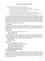
Bạn đang xem bản rút gọn của tài liệu. Xem và tải ngay bản đầy đủ của tài liệu tại đây (1.5 MB, 40 trang )
CH-7
CHASSIS — A750F AUTOMATIC TRANSMISSION
A750F AUTOMATIC TRANSMISSION
JDESCRIPTION
The A750F 5-speed Super ECT (Electronic Controlled Transmission) is used on the 2UZ-FE and 1GR-FE
engine models.
CH
081CH06Y
"
Specifications A
Engine Type
Gear Ratio
2UZ-FE
1GR-FE
1st
3.520
¬
2nd
2.042
¬
3rd
1.400
¬
4th
1.000
¬
5th
0.716
¬
Reverse
3.224
¬
Toyota Genuine
ATF WS
¬
Fluid Type
Fluid Capacity
with Water Cooled Oil Cooler + ATF
Warmer
10.9 (11.5, 9.6)
¬
Liters (US qts, Imp. qts)
with Water Cooled Oil Cooler + Air
cooled ATF Cooler
11.1 (11.7, 9.8)
¬
Weight (Reference)*
with Water Cooled Oil Cooler + ATF
Warmer
86.0 (189.6)
86.5 (190.7)
with Water Cooled Oil Cooler + Air
cooled ATF Cooler
86.1 (189.8)
86.7 (191.1)
kg (lb)
*: Weight shows the figure with the fluid fully filled.
NM
0810E
CH-8
CHASSIS — A750F AUTOMATIC TRANSMISSION
C3
B1
B3
B2
F1
Input Shaft
C2
C1
B4
F3
Rear Planetary Gear
Center Planetary Gear
F2
081CH07Y
Front Planetary Gear
C1
No.1 Clutch
7
C2
No.2 Clutch
6
C3
No.3 Clutch
5
B1
No.1 Brake
B2
No.2 Brake
3
B3
No.3 Brake
4
B4
No.4 Brake
8
F1
No.1 One-way Clutch
18
F2
No.2 One-way Clutch
F3
No.3 One-way Clutch
4
The No. of Discs
25
The No. of Sprags
p g
26
The No. of Sun Gear Teeth
Front Planetary Gear
Center Planetary
y Gear
Rear Planetary
y Gear
The No
No. of Pinion Gear Teeth
40
Inner
22
Outer
21
The No. of Ring Gear Teeth
91
The No. of Sun Gear Teeth
31
The No. of Pinion Gear Teeth
23
The No. of Ring Gear Teeth
77
The No. of Sun Gear Teeth
25
The No. of Pinion Gear Teeth
19
The No. of Ring Gear Teeth
63
NM
0810E
CH-9
CHASSIS — A750F AUTOMATIC TRANSMISSION
JTORQUE CONVERTER CLUTCH
A compact, lightweight and high-capacity torque converter clutch is used. The torque converter clutch
supports flex lock-up clutch control, thus allowing for improved fuel economy.
"
Specifications A
Torque Converter
Clutch Type
Stall Torque
Ratio
Turbine Runner
3-element, 1-step, 2-phase
2UZ-FE
1.8
1GR-FE
1.9
Pump
Impeller
Lock-up
Clutch
Stator
CH
One-way
Clutch
279CH08
JOIL PUMP
The oil pump is driven by the torque converter clutch. It lubricates the planetary gear units and supplies
operating fluid pressure for hydraulic control.
Front Pump Body
Front Oil Pump
Drive Gear
Front Oil Pump
Driven Gear
Stator Shaft
081CH08Y
NM
0810E
CH-10
CHASSIS — A750F AUTOMATIC TRANSMISSION
JATF COOLING SYSTEM
1. General
This automatic transmission uses an ATF warmer that accelerates a rise in the ATF temperature, and an ATF
cooler that cools down ATF. The settings of an ATF warmer, water cooled oil cooler, and air cooled vary in
accordance with the destinations.
f: Standard —: Not available
Europe
China
Australia
G.C.C.
Countries
General
Countries
f
f
—
—
—
Water Cooled
f
f
f
f
f
Air Cooled
—
—
f
f
f
Items
ATF Warmer
Oil Cooler
"
Cooling Circuits A
AT
ATF Warmer
AT
Thermostat
AT
ATF Warmer
AT
Thermostat
Water Cooled
Oil cooler
Water Cooled
Oil cooler
080CH02Y
ATF Warmer + Water Cooled Oil Cooler
AT
Water Cooled
Oil cooler
Air Cooled
Oil cooler
081CH09Y
Water Cooled Oil Cooler +Air Cooled Oil Cooler
NM
0810E
CH-11
CHASSIS — A750F AUTOMATIC TRANSMISSION
2. ATF WARMER
General
D The ATF warmer uses engine coolant to warm up the ATF quickly and keep the ATF temperature higher
(within limits). Consequently, the friction losses of the automatic transmission are quickly reduced, thus
improving fuel economy.
D The ATF warmer has a transmission oil thermostat that changes the route through which the ATF flows.
When the ATF temperature is low, it is heated by the ATF warmer using the engine coolant, and when
the temperature is high, it is cooled down by the ATF warmer and oil cooler.
To Engine
: Engine Coolant Flow
: ATF Flow
From Engine
CH
ATF Warmer
To A/T
Transmission Oil
Thermostat
From A/T
Side View
To Oil Cooler
From Oil Cooler
"
081CH10TE
System Diagram A
Engine
A/T
Transmission Oil Thermostat
Heater
Core
Oil Cooler
ATF Warmer
04E0CH54C
NM
0810E
CH-12
CHASSIS — A750F AUTOMATIC TRANSMISSION
Transmission Oil Thermostat
The transmission oil thermostat consists of the poppet valve, bypass valve and element case (contains wax).
When the ATF temperature changes from low to high, the wax will expand to start to open the poppet valve
and close the bypass valve, thus switching the ATF passages.
To A/T
ATF Flow
From Oil Cooler
Poppet Valve: Close
Element Case (Contains Wax)
Bypass Valve: Open
From A/T
To Oil Cooler
04E0CH52C
ATF Temperature: Low
To A/T
ATF Flow
From Oil Cooler
Poppet Valve: Open
Element Case (Contains Wax)
Bypass Valve: Close
From A/T
To Oil Cooler
04E0CH109C
ATF Temperature: High
NM
0810E
CH-13
CHASSIS — A750F AUTOMATIC TRANSMISSION
3. OIL COOLER
D The water cooled oil cooler cools down the ATF using the engine coolant, and is fitted on the lower of
the radiator.
D The air cooled oil cooler cools down the ATF using the cooling fins which are provided on the cooler itself,
and is fitted inside the radiator grille so that it can be exposed to the air directly while the vehicle is running.
"
Models ATF Warmer + Water Cooled Oil Cooler A
Front
CH
Water Cooled Oil Cooler
ATF Warmer
081CH11TE
"
Models Water Cooled Oil Cooler + Air Cooled Oil Cooler A
Front
Air Cooled
Oil Cooler Core
Water Cooled Oil Cooler
081CH12TE
NM
0810E
CH-14
CHASSIS — A750F AUTOMATIC TRANSMISSION
JTOYOTA GENUINE ATF WS
D Toyota Genuine ATF WS is used to reduce the resistance of the ATF and improve the fuel economy by
reducing its viscosity in the practical operating temperature range. At higher ATF temperatures, the
viscosity is the same as that of Toyota Genuine ATF type T-IV, which ensures the durability of the
automatic transmission.
D There is no interchangeability between Toyota Genuine ATF WS and other types of ATF.
Viscosity
: Toyota Genuine ATF Type T-IV
: Toyota Genuine ATF WS
Reduced Viscosity
High
High
Temperature
259LSK03
JATF FILLING PROCEDURE
An ATF filling procedure is used in order to improve the accuracy of the ATF level when the transmission
is being repaired or replaced. As a result, the oil filler tube and the oil level gauge used in the conventional
automatic transmission have been discontinued, eliminating the need to inspect the fluid level as a part of
routine maintenance.
D This filling procedure uses a refill plug, overflow plug, No.2.ATF temperature sensor and shift position
indicator light “D”.
Refill Plug
Overflow Plug
Proper Level in ATF Fill Mode
04E0CH36C
NM
0810E
CH-15
CHASSIS — A750F AUTOMATIC TRANSMISSION
Service Tip
ATF Filling procedure using SST (09843-18040)
When a large amount of ATF needs to be filled (i.e. after removal and installation of oil pan or torque
converter clutch), perform the procedure from step 1.
When a small amount of ATF is required (i.e. removal and installation of oil cooler tube, repair of a
minor oil leak), perform the procedure from step 5.
Keep the vehicle level. Turn off the AHC height control switch before raising the vehicle.
1) Remove the refill plug and overflow plug.
2) Fill the transmission with WS type ATF through the refill plug hole until it overflows from the
overflow plug hole.
D ATF WS must be used to fill the transmission.
3) Reinstall the overflow plug.
4) Add the specified amount of ATF (specified amount is determined by the procedure that was
performed) and reinstall the refill plug.
Example:
Procedure
Amount
Liters (US qts, Imp.qts)
Removal and installation of an oil pan (including oil drainage)
1.7 (1.80, 1.50)
Removal and installation of a transmission valve body
4.3 (4.54, 3.78)
Replacement of a torque converter clutch
5.4 (5.71, 4.75)
CH
CG
5) Use the SST (09843-18040) to make shorts
between the TC and CG terminals of the DLC3
connector:
6) Start the engine and allow it to idle.
D A/C switch must be turned off.
7) Move the shift lever from the P position to the
TC
S mode position and slowly selects each gear
DLC3
259LSK78
S1 - S5. Then move the shift lever back to the
P position.
8) Move the shift lever to the D position, and then quickly move it back and forth between N and D
(at least once every 1.5 seconds) for at least 6 seconds. This will activate oil temperature detection
mode.
Standard: The shift position indicator light “D” remains illuminated for 2 seconds and then
goes off.
9) Return the shift lever to the P position and disconnect the TC terminal.
10) Idle the engine to raise the ATF temperature.
11) Immediately after the shift position indicator “D” light turns on, lift the vehicle up.
D The shift position indicator light “D” will indicate the ATF temperature according to the following
table.
ATF Temp.
Shift Position
Indicator Light “D”
Lower than
Proper Temp.
Proper Temp.
Higher than
Proper Temp.
Turn OFF
Turn ON
Blinking
(Continued)
NM
0810E
CH-16
CHASSIS — A750F AUTOMATIC TRANSMISSION
12) Remove the overflow plug and adjust the oil quantity.
D If the ATF overflows, go to step 15, and if the ATF does not overflow, go to step 13.
13) Remove the refill plug.
14) Add ATF through the refill plug hole until it flows out from the overflow plug hole.
15) When the ATF flow slows to a trickle, install the overflow plug and a new gasket.
16) Reinstall the refill plug (if the refill plug was removed).
17) Turn the engine switch OFF to stop the engine.
For details about the ATF Filling procedures, see the Land Cruiser (Station Wagon) Repair Manual
(Pub. No. RM0810E).
NM
0810E
CH-17
CHASSIS — A750F AUTOMATIC TRANSMISSION
JPLANETARY GEAR UNIT
1. Construction
The planetary gear unit consists of three planetary gear units, three clutches, four brakes, and three one-way
clutches.
D A centrifugal fluid pressure canceling mechanism is used in the C1, C2, and C3 clutches that are applied
when shifting from 2nd ® 3rd, 3rd ® 4th, and 4th ® 5th. For details, see page CH-22.
B3
F2
B1
F1
C3
Input Shaft
B2
Front Planetary
Gear
B4
F3
CH
C1
Output Shaft
Sun Gear
C2
Intermediate Shaft
Rear
Planetary
Center Planetary
Gear
Gear
04E0CH01C
2. Function of Components
Components
Function
C1
No.1 Clutch
Connects the input shaft and intermediate shaft.
C2
No.2 Clutch
Connects the input shaft and center planetary carrier.
C3
No.3 Clutch
Connects the input shaft and front sun gear.
B1
No.1 Brake
Prevents the front planetary carrier from turning either clockwise or
counterclockwise.
B2
No.2 Brake
Prevents the front and center ring gear from turning either clockwise or
counterclockwise.
B3
No.3 Brake
Prevents the outer race of F2 from turning either clockwise or
counterclockwise.
B4
No.4 Brake
Prevents the center planetary carrier and rear ring gear from turning either
clockwise or counterclockwise.
F1
No.1 One-way Clutch
Prevents the front planetary carrier from turning counterclockwise.
F2
No.2 One-way Clutch
When B3 is operating, this one-way clutch prevents the front planetary
sun gear from turning counterclockwise.
F3
No.3 One-way Clutch
Prevents the center planetary carrier and rear ring gear from turning
counterclockwise.
Planetary Gears
These gears change the route through which driving force is transmitted,
in accordance with the operation of each clutch and brake, in order to
increase or reduce the input and output speed.
NM
0810E
CH-18
CHASSIS — A750F AUTOMATIC TRANSMISSION
3. Transmission Power Flow
Shift Lever
P ii
Position
D,
Solenoid Valve
S1
S1
SLU
C1
R*
ON
ON
N
ON
ON
1st
ON
ON
f
2nd
ON
ON
ON
f
ON
ON
f
ON
f
4th*
ON
1st
ON
2nd
ON
3rd
ON
ON
ON
f
ON
ON
f
ON
ON
f
ON
1st
ON
2nd
ON
3rd*
S2
SL2
ON
4th*
S3
SL1
ON
5th*
S4
SR
P
3rd
S5
S2
Clutch
ON
ON
2nd*
ON
f
ON
f
1st*
ON
f
ON
ON
f
ON
ON
1st
ON
ON
C2
One-way
Clutch
Brake
C3
B1
f
D
B2
B3
B4
F1
f
f
F2
f
f
f
f
F
f
f
F
F
f
f
f
f
F
f
f
f
f
f
F
f
F
F
f
f
f
D
f
f
F
f
f
f
f
f
F3
f
D
f
f
D
f
f
f: Operates
F: Operates
but is not related to power transmission
D: Operates during engine braking
*: with engine brake
NM
0810E
CH-19
CHASSIS — A750F AUTOMATIC TRANSMISSION
1st Gear (D Position or S Mode)
B3
F2
B1
B2
F1
B4
F3
C3
C1
C2
CH
: Operates
: Operates only in the S1 range
04E0CH02C
2nd Gear (D Position or S Mode)
B3
F2
B1
B2
F1
B4
F3
C3
C1
C2
: Operates
: Operates only in the S2 range
04E0CH03C
NM
0810E
CH-20
CHASSIS — A750F AUTOMATIC TRANSMISSION
3rd Gear (D Position or S Mode)
B3
F2
B1
B2
F1
B4
F3
C3
C1
C2
: Operates
: Operates only in the S3 range
: Operates but is not related to power transmission
04E0CH04C
4th Gear (D Position or S mode)
B3
F2
B1
B2
F1
B4
F3
C3
C1
C2
: Operates
: Operates but is not related to power transmission
04E0CH05C
NM
0810E
CHASSIS — A750F AUTOMATIC TRANSMISSION
CH-21
5th Gear (D Position or S Mode)
B3
F2
B1
B2
F1
B4
F3
C3
C1
C2
CH
: Operates
: Operates but is not related to power transmission
04E0CH06C
Reverse Gear (R Position)
B3
F2
B1
B2
F1
B4
F3
C3
C1
C2
: Operates
: Operates during engine braking
04E0CH07C
NM
0810E
CH-22
CHASSIS — A750F AUTOMATIC TRANSMISSION
4. Centrifugal Fluid Pressure Canceling Mechanism
For the following reason, the centrifugal fluid pressure canceling mechanism is used on the C1, C2, and C3
clutches.
D Clutch shifting operation is affected not only by the valve body controlling fluid pressure but also by
centrifugal fluid pressure that is present due to fluid in the clutch piston oil pressure chamber. The
centrifugal fluid pressure canceling mechanism has chamber B to reduce this affect applied to the chamber
A. As a result, smooth shifting with excellent response has been achieved.
Piston
Chamber A
C1 Clutch
C1 Clutch
Chamber B
C3 Clutch
C2 Clutch
Centrifugal Fluid Pressure
applied to the Chamber A
04E0CH127C
Clutch
Target Fluid Pressure
Centrifugal Fluid Pressure
applied to Chamber B
Piston Fluid
Pressure
Chamber
Chamber B
(Lubrication Fluid)
Fluid Pressure
applied to Piston
Shaft Side
157CH17
Fluid pressure
applied to piston
—
Centrifugal fluid pressure
applied to chamber B
=
Target fluid pressure
(original clutch pressure)
NM
0810E
CH-23
CHASSIS — A750F AUTOMATIC TRANSMISSION
JVALVE BODY UNIT
1. General
The valve body unit consists of the (No.1 and No.2) upper and lower valve bodies and 7 solenoid valves.
Shift Solenoid Valve SR
Shift Solenoid Valve SLU
Shift Solenoid Valve SL2
No.2 Upper Valve Body
No.1 Upper Valve Body
CH
Shift Solenoid Valve S2
Shift Solenoid Valve S1
Lower Valve Body
Shift Solenoid Valve SL1
Shift Solenoid Valve SLT
"
229LC161
No.1 Upper Valve Body A
Solenoid Modulator Valve
B1 Accumulator
Clutch Lock Valve
2 - 3 Shift Valve
1 - 2 Shift Valve
B1 Apply Control Valve
Brake Control Valve
Secondary Regulator Valve
Lock-up Relay Valve
3 - 4 Shift Valve
C3 Check Valve
Lock-up Control Valve
229LC162
NM
0810E
CH-24
"
CHASSIS — A750F AUTOMATIC TRANSMISSION
No.2 Upper Valve Body A
Coast Brake Relay Valve
"
229LC163
Lower Valve Body A
Clutch Apply Control Valve
Sequence Valve
SLT Damper
Clutch Control Valve
Primary Regulator Valve
Accumulator Control Valve
229LC164
NM
0810E
CH-25
CHASSIS — A750F AUTOMATIC TRANSMISSION
2. Shift Solenoid Valve
Shift Solenoid Valve S1, S2 and SR
D Solenoid valves S1 and SR use a 3-way solenoid valve.
D Solenoid valve S2 uses a 2-way solenoid valve.
D A filter is provided at the tip of each solenoid valve to further improve operational reliability.
Drain
Filter
Line
Pressure
Control Pressure
CH
Control Pressure
Shift Solenoid Valve S1 ON
Shift Solenoid Valve S1 OFF
229LC165
Control Pressure
Filter
Line Pressure
Shift Solenoid Valve S2
Shift Solenoid Valve S2 OFF
229LC166
"
Function of Shift Solenoid Valve S1, S2 and SR A
Shift Solenoid Valve
Type
Function
S1
3-way
Switches the 2 - 3 shift valve
S2
2-way
· Switches the 1 - 2 shift valve
· Switches the 3 - 4 shift valve
SR
3-way
Switches the clutch apply control valve
NM
0810E
CH-26
CHASSIS — A750F AUTOMATIC TRANSMISSION
Shift Solenoid Valve SL1, SL2, SLT and SLU
D SL1, SL2, SLT, and SLU are used by the ECM to control hydraulic pressures in a linear fashion based
on the current that the ECM causes to flow through their solenoid coils. They control line, clutch, and
brake engagement pressure based on the signals received from the ECM.
D The shift solenoid valves SL1, SL2, SLT, and SLU have the same basic structure.
Sleeve
Spool Valve
Solenoid Coil
Shift Solenoid Valve SLT
Hydraulic
Pressure
Hydraulic
Pressure
Current
Current
Shift Solenoid Valve SL1, SL2, and SLT
Shift Solenoid Valve SLU
229LC181
"
Function of Shift Solenoid Valve SL1, SL2, SLT and SLU A
Shift Solenoid Valve
Function
SL1
· Clutch pressure control
· Accumulator back pressure control
SL2
Brake pressure control
SLT
· Line pressure control
· Accumulator back pressure control
SLU
Lock-up clutch pressure control
NM
0810E
CHASSIS — A750F AUTOMATIC TRANSMISSION
CH-27
JELECTRONIC CONTROL SYSTEM
1. General
The electronic control system of the A750F automatic transmission consists of the control functions listed
below.
System
Shift Timing Control
Clutch Pressure Control
(See Page CH-36)
Line Pressure Optimal Control
(See Page CH-37)
Function
The ECM sends current to shift solenoid valves S1, S2 or SR based on
signals from various sensors in order to shift the gears.
· Controls the pressure that is applied directly to B1 brake and C1
clutch by actuating the shift solenoid valves SL1 and SL2 in
accordance with the ECM signals.
· The shift solenoid valve SLT and SL1 minutely controls the clutch
pressure in accordance with the engine output and driving conditions.
Actuates the shift solenoid valve SLT to control the line pressure in
accordance with information from the ECM and the operating
conditions of the transmission.
Engine Torque Control
Retards the engine ignition timing temporarily to improve shift feeling
while up-shifts or downshifts occur.
Lock-up Timing Control
The ECM sends current to the shift solenoid valve SLU based on
signals from various sensors and engages or disengages the lock-up
clutch.
Flex Lock-up Clutch Control
(See Page CH-38)
Controls the shift solenoid valve SLU, provides an intermediate mode
for when the lock-up clutch is between ON and OFF, increasing the
operating range of the lock-up clutch to improve fuel economy.
“N” to “D” Squat Control
When the shift lever is shifted from “N” to “D” position, 2nd gear is
temporarily engaged before 1st to reduce vehicle squat.
“R” to “D” Squat Control
When the shift lever is shifted from “R” to “D” position, 3rd gear is
temporarily engaged before 1st to reduce vehicle squat.
2nd Start Control
Enabling the vehicle to take off in the 2nd gear and thus make it easy
to take off snowy, sandy or muddy terrain.
AI (Artificial Intelligence)
-SHIFT Control
(See Page CH-39)
Based on the signals from various sensors, the ECM determines the
road conditions and the intention of the driver. Thus, an appropriate
shift pattern is automatically determined, thus improving drivability.
Multi-mode Automatic
Transmission
(See page CH-41)
The ECM appropriately controls the automatic transmission in
accordance with the range position selected while the shift lever is in
the S mode position.
Diagnosis
(See Page CH-43)
When the ECM detects a malfunction, the ECM records the
malfunction and memorizes the information that relates to the fault.
Fail-safe
(See Page CH-43)
If a malfunction is detected in the sensors or solenoids, the ECM effects
fail-safe control to prevent the vehicle’s drivability from being affected
significantly.
CH
NM
0810E
CH-28
CHASSIS — A750F AUTOMATIC TRANSMISSION
2. Construction
The configurations of the electronic control system for the A750F automatic transmission is as shown in the
following chart.
"
2UZ-FE Engine Model A
MASS AIR FLOW METER
CRANKSHAFT POSITION
SENSOR
VG
S1
S2
NE
SL1
THROTTLE POSITION SENSOR
VTA1
SHIFT SOLENOID VALVE S2
SHIFT SOLENOID VALVE SL1
VTA2
SL2
ACCELERATOR PEDAL
POSITION SENSOR
SHIFT SOLENOID VALVE S1
SHIFT SOLENOID VALVE SL2
VPA
VPA2
ENGINE COOLANT
TEMPERATURE SENSOR
THW
NO.1 ATF TEMPERATURE
SENSOR
THO1
NO.2 ATF TEMPERATURE
SENSOR
THO2
SLT
SLU
ECM
SR
SHIFT SOLENOID VALVE SLT
SHIFT SOLENOID VALVE SLU
SHIFT SOLENOID VALVE SR
ESA
IGT
1, 4, 6, 7
IGF1
PARK/NEUTRAL
POSITION SWITCH
NSW
IGT
2, 3, 5, 8
P, N, R, D
IGF2
Ignition Coil (with Igniter)
No.1, 4, 6, 7
Ignition Coil (with Igniter)
No.2, 3, 5, 8
S
TRANSMISSION CONTROL
SWITCH
SFTU
SFTD
Spark Plugs
No.2, 3, 5, 8
Spark Plugs
No.1, 4, 6, 7
(Continued)
081CH13S
NM
0810E
CH-29
CHASSIS — A750F AUTOMATIC TRANSMISSION
COMBINATION METER
SPEED SENSOR NT
SPD
NT
VEHICLE SPEED SIGNAL
W
SPEED SENSOR SP2
Check Engine Warning Light
SP2
Multi-information Display*1
· Shift Range Indicator
· ATF Temp. Warning Indicator
ECM
STOP LIGHT SWITCH
Master Warning Light*1
STP
ECT Power Indicator Light
4WD CONTROL ECU
L4
CANH
CANL
2nd Start Indicator Light
CH
Shift Range Indicator Light*2
S Mode Indicator Light*2
TRANSFER INDICATOR SWITCH
ATF Temperature
Warning Light*2
TFN
Buzzer
CAN (V Bus)
PATTERN SELECT SWITCH
PWR
SNWI
*1: Only for models with optitron type combination meter
*2: Only for models with analog type combination meter
DLC3
TC
081CH63S
NM
0810E
CH-30
"
CHASSIS — A750F AUTOMATIC TRANSMISSION
1GR-FE Engine Model A
MASS AIR FLOW METER
CRANKSHAFT POSITION
SENSOR
THROTTLE POSITION SENSOR
ACCELERATOR PEDAL
POSITION SENSOR
ENGINE COOLANT
TEMPERATURE SENSOR
VG
S1
NE
S2
VTA1
SL1
VTA2
SHIFT SOLENOID VALVE S1
SHIFT SOLENOID VALVE S2
SHIFT SOLENOID VALVE SL1
VPA
SL2
VPA2
SHIFT SOLENOID VALVE SL2
THW
SLT
SHIFT SOLENOID VALVE SLT
SLU
SHIFT SOLENOID VALVE SLU
ECM
NO.1 ATF TEMPERATURE
SENSOR
THO1
NO.2 ATF TEMPERATURE
SENSOR
THO2
PARK/NEUTRAL
POSITION SWITCH
SR
SHIFT SOLENOID VALVE SR
NSW
P, N, R, D
IGT1 to
IGT6
ESA
Ignition Coil (with Igniter)
S
TRANSMISSION CONTROL
SWITCH
IGF1
SFTU
SFTD
Spark Plugs
(Continued)
081CH15S
NM
0810E
CH-31
CHASSIS — A750F AUTOMATIC TRANSMISSION
SPEED SENSOR NT
NT
COMBINATION METER
SPD
SPEED SENSOR SP2
SP2
STOP LIGHT SWITCH
STP
Vehicle Speed Signal
W
Check Engine Warning Light
ECM
ECT Power Indicator Light
CANH
CANL
4WD CONTROL ECU
2nd Start Indicator Light
Shift Range Indicator Light
L4
S Mode Indicator Light
TRANSFER INDICATOR SWITCH
ATF Temperature
Warning Light
TFN
CH
Buzzer
CAN (V Bus)
PATTERN SELECT SWITCH
PWR
SNW1
DLC3
TC
081CH62S
NM
0810E