Smart home systems Part 5 doc
Bạn đang xem bản rút gọn của tài liệu. Xem và tải ngay bản đầy đủ của tài liệu tại đây (496.16 KB, 15 trang )
SelectedHomeAutomationandHomeSecurityRealizations:AnImprovedArchitecture 51
The JK Flip flops working as flag bits of the relay register has asynchronous bits Preset (PR’)
and Clear (CLR’) and the command is exerted through them. The figure shows only flip flop.
The Enable bit (En) arrives from the decoded appliance code and the ON/OFF’ bit arrives
due to action code. For instance if the 5
th
appliance is commanded then En bit of the 5
th
flip
flop becomes ‘1’ and if ON command arrives ON/OFF’ bit becomes ‘1’ causing PR’ to ‘0’ as
to set the flip flop (‘1’). Obviously if ON/OFF’ is ‘0’ then flip flop would be cleared.
Fig. 5. Updating the bit of Relay Register
Fig. 6. Telephonic Control of appliances
Ring Detector
G
y
r
a
t
o
r
Control
Bridge
Rin
g
e
Transceiver
Cradle
Relay
Appliances
J Q
K Q’
En
ON/OFF
’
En
PR’
CLR’
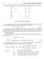
3.3 Telephonic Method of Control
Landline telephony has been serving as the major communication media used for tele-
conversation. Although the launching of cellular telephony and the internet based voice
communication has reduced its usage, landline telephonic network still enjoys its service
due to its simplicity and cost effectiveness offered to subscribers. Using landline telephone
controls were issued (Balasubramanian, 2003) by dialing additional digits for switching ON
or OFF of the electrical appliances in home. An extension card attached to the home
telephone identifies the digit, decodes it and controls switching the appliances. Its principle
is outlined in Fig.6.
In order to control switching the appliances in home the user dials the digits of home
telephone. This gives ring in home telephone. The extension card attached to it counts the
ring cycles and actuates a relay to close the cradle contacts despite the handset unmoved
from cradle. The closing of contacts extends a gyrator and control bridge across the lines
simulating the condition of establishing connection to home set. The additional digit dialed
is decoded and the corresponding appliance is switched ON/OFF by the relay circuit.
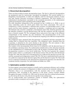
3.4 Comparison of Remote Control Techniques
In order to compare the features of remote control techniques considered here a simple
hardware scheme employing these control methods in home automation unit is shown in
Fig.7. It does not, however, show the intruder detector and fire detector alarm units.
Assuming all selected control schemes are available in the flat their features and
performances are compared. The final control element of appliances of all control units are
delivered from the relay board as commanded by word in relay register. At any instant of
issuing the command from remote location the concerned control unit will write the control
word into the relay register through the logic circuit and consequently the selected
appliance would be operated. If the resident is in home as identified by the status switch ‘S’
the manual control bit would replace the remote control bit in the relay register.
3.4.1 Web Method
This is active method of controlling the appliances. The user can learn the status of the
appliance whether it is switched ON or OFF and then issue order accordingly. The
hardware required for this unit is the microcontroller interfaced to the web server. The
command word is written into the relay register from the web through microcontroller and
logic circuit. Access for control is almost instantaneous so long as the internet is of high
speed and is active. Drawbacks of this method are the interruptions arising in internet at
web server level or in channels including the satellite media.
3.4.2 Email Method
Email method of control is a passive control type that it does not check the present status of
the appliance whether switched ON or OFF and simply issues order to selected appliance to
either switch ON or OFF. While web control technique is almost instantaneous in executing
the orders while the internet is active, the email method takes relatively longer time
depending upon the type of the email platform employed. It also needs internet connection
in order to carry on control activities. Since email is given from a remote PC web mail
feature could be employed for controlling appliances.
SmartHomeSystems52
3.4.3 SMS Control
Since cellular network is independent from internet and landline telephone network it needs
just cellular phone for passing the control digits to the relay register. Neither PC nor its
connection to internet is needed for control through SMS. From remote mobile phone an
SMS need be sent to the home mobile phone for effecting the control of the appliance. The
hardware requirement is therefore simpler than other methods of control.
3.4.4 Telephone Dialling
Landline telephone dialing is another simple method of control. Here the landline telephone
is attached with an extension card and kept in home such that when the control digit is
dialed from external phone it is identified and passed to the relay register for effecting the
control. This control unit is simple and is involved in telephone loop independent of the
internet connectivity. Unlike web based control there is no facility to check the status of the
appliance before commanding the control.
Fig. 7. Selected Remote Control Schemes Installed in Home
3.4.5 Further Discussions
Only remote control aspect of home automation system is considered here for its betterment
and easy implementation. Essential schemes for remote control of appliances are proposed
here and depending upon the circumstances and requirements one or more of the schemes
Telephone
Equipment
PC
Commn Terminal
Logic
L1
R
e
l
a
y
R
e
g
Rela
y
Board
Appliances
Web Server
To other
flats
Micro-
controller
Extension
Board
Cell
Phone
I/O
Interface
Trigger from
PC, Web micro-controller
Telephone extension board
Cell phone I/O interface
Displa
y
can be chosen for installation in a given system. Relay register and relay board unit is the
essential hardware unit present in the home automation system where selected remote
control schemes could control the bits in relay register. Whatever may the control technique
used in the system the final control element would be the relay operating to switch ON or
OFF of the selected appliance. Internet based control performed through web is versatile
and interactive in controlling the appliances. If more and more appliances are needed to be
controlled then an encoder is needed to be used in the transmitter to have the standard
word length of 16-bits for the control word. In the receiver the 16-bit control word is
decoded and the corresponding bits are taken to the relays for switching the appliances.
In simple automation system where internet facilities are not provided one can opt cellular
phone based control scheme which is simple and cost effective. Alternatively for such
requirements landline telephone with an extension card could also be opted.
3.5 Personal Digital Assistant
The personal Digital software is installed in PC which is linked to the operating system that
brings the daily chart to the screen of the PC monitor. In the database accessible to the OS,
the various activities to be done on different dates and times are pre-programmed and this
updated daily by the user. The personal digital software refers the home data base every
morning at the set time and brings the list of activities to be done on that day to screen as to
alert the user to be ready for solving the issues of the day.
4. Home Security Concerns
An important home security aspect insists that the fire accident that can happen in home
during the absence of the resident should be alerted and intimated to a remote location. Also
intruder making unauthorized entry into the flat should also be informed to a remote
location for taking follow up actions. Authorized visitor entry supported by video image
presentation is another aspect which helps in security concerns.
4.1 Fire and Intruder Alert
4.1.1 Fire Detection and Intimation
The occurrence fire in home is detected electronically. It is then sent as SMS and then
converted into email and sent again to a remote PC. The arrival of email in remote PC
executes a file to create an alarming sound. The email can also be received in a cell phone
causing a beep sound. Also the detection of intruder by a sensor sends another SMS which is
converted into email as to make appropriate indication in remote PC or in cell phone.
4.1.1.1 System Overview
A simple scheme sending SMS upon fire detection or intruder detection and then its email
conversion is shown in Fig.8. An 8085 based microprocessor system is extended to light and
heat sensors through interrupt interface. Through I/O ports of the microcomputer a GSM
module is connected. The GSM module is backed up with the facilities of TynTec system
(Tyntec website, 2009). If excessive light or heat is sensed electronically in the flat and if any
of its voltage exceeds the threshold then it interrupts the microcomputer (RST7.5). The
SelectedHomeAutomationandHomeSecurityRealizations:AnImprovedArchitecture 53
3.4.3 SMS Control
Since cellular network is independent from internet and landline telephone network it needs
just cellular phone for passing the control digits to the relay register. Neither PC nor its
connection to internet is needed for control through SMS. From remote mobile phone an
SMS need be sent to the home mobile phone for effecting the control of the appliance. The
hardware requirement is therefore simpler than other methods of control.
3.4.4 Telephone Dialling
Landline telephone dialing is another simple method of control. Here the landline telephone
is attached with an extension card and kept in home such that when the control digit is
dialed from external phone it is identified and passed to the relay register for effecting the
control. This control unit is simple and is involved in telephone loop independent of the
internet connectivity. Unlike web based control there is no facility to check the status of the
appliance before commanding the control.
Fig. 7. Selected Remote Control Schemes Installed in Home
3.4.5 Further Discussions
Only remote control aspect of home automation system is considered here for its betterment
and easy implementation. Essential schemes for remote control of appliances are proposed
here and depending upon the circumstances and requirements one or more of the schemes
Telephone
Equipment
PC
Commn Terminal
Logic
L1
R
e
l
a
y
R
e
g
Rela
y
Board
Appliances
Web Server
To other
flats
Micro-
controller
Extension
Board
Cell
Phone
I/O
Interface
Trigger from
PC, Web micro-controller
Telephone extension board
Cell phone I/O interface
Displa
y
can be chosen for installation in a given system. Relay register and relay board unit is the
essential hardware unit present in the home automation system where selected remote
control schemes could control the bits in relay register. Whatever may the control technique
used in the system the final control element would be the relay operating to switch ON or
OFF of the selected appliance. Internet based control performed through web is versatile
and interactive in controlling the appliances. If more and more appliances are needed to be
controlled then an encoder is needed to be used in the transmitter to have the standard
word length of 16-bits for the control word. In the receiver the 16-bit control word is
decoded and the corresponding bits are taken to the relays for switching the appliances.
In simple automation system where internet facilities are not provided one can opt cellular
phone based control scheme which is simple and cost effective. Alternatively for such
requirements landline telephone with an extension card could also be opted.
3.5 Personal Digital Assistant
The personal Digital software is installed in PC which is linked to the operating system that
brings the daily chart to the screen of the PC monitor. In the database accessible to the OS,
the various activities to be done on different dates and times are pre-programmed and this
updated daily by the user. The personal digital software refers the home data base every
morning at the set time and brings the list of activities to be done on that day to screen as to
alert the user to be ready for solving the issues of the day.
4. Home Security Concerns
An important home security aspect insists that the fire accident that can happen in home
during the absence of the resident should be alerted and intimated to a remote location. Also
intruder making unauthorized entry into the flat should also be informed to a remote
location for taking follow up actions. Authorized visitor entry supported by video image
presentation is another aspect which helps in security concerns.
4.1 Fire and Intruder Alert
4.1.1 Fire Detection and Intimation
The occurrence fire in home is detected electronically. It is then sent as SMS and then
converted into email and sent again to a remote PC. The arrival of email in remote PC
executes a file to create an alarming sound. The email can also be received in a cell phone
causing a beep sound. Also the detection of intruder by a sensor sends another SMS which is
converted into email as to make appropriate indication in remote PC or in cell phone.
4.1.1.1 System Overview
A simple scheme sending SMS upon fire detection or intruder detection and then its email
conversion is shown in Fig.8. An 8085 based microprocessor system is extended to light and
heat sensors through interrupt interface. Through I/O ports of the microcomputer a GSM
module is connected. The GSM module is backed up with the facilities of TynTec system
(Tyntec website, 2009). If excessive light or heat is sensed electronically in the flat and if any
of its voltage exceeds the threshold then it interrupts the microcomputer (RST7.5). The
SmartHomeSystems54
interrupt service subroutine is arranged to send a text message to GSM module which in
turn sends an email to the number provided by TynTec. The two way SMS online tool of the
TynTec converts the SMS into an email and forwards to the specified email-id. This email
message can be received in an internet backed PC. As described before the email platform is
set up with a rule such that as soon as the email arrives with a specific word in the text the
exe file would run a set of instructions as to give alarming message. The email can also be
received in a cell phone causing beep sound alerting the user. The detection of intruder
interrupts the microprocessor on the interrupt line RST6.5. The interrupt service subroutine
of RST6.5 sends the related message to GSM module and this in turn sends the email to the
concerned email-id.
The detection of fire is made by sensing the exhaustive heat or light electronically and
comparing with a threshold. The sensor circuit is shown in Fig.9. In place of Rx, LDR is used
for light sensing and thermistor is used for heat sensing. These sensitive elements are kept at
selected spots in the home. Rx might be a single element or an array of elements where all
elements representing Rx are connected in parallel to the sensor circuit. If anyone becomes
active it pulls down the effective resistance of Rx resulting in increased voltage to the
comparator.
Fig. 8. Simple Schematic of Alarming by Fire and Intruder Detection
Light
Detector
Heat
Detector
Micro
controller
Interrupts
Port
Tx Rx
GSM Module
RST7.5
RST6.5
Intruder
Detector
Fig. 9. Sensor Circuit
4.1.1.2 Fire Detector Actuates Telephone dialling
As an alternative to SMS and email alert, the fire detector can be arranged to actuate dialling
through landline phone kept in home to the resident’s mobile phone. An electronic dialling
circuit attached to home telephone can be triggered by exerting actuating signal obtained
from any type of detector circuit (Balasubramanian and Cellatoglu, 2008). The actuating
signal given to it does two things; i. it operates a relay circuit to close the cradle for a pre-
determined time so as to receive dial tone and to commence dialling, ii. it provides enable
signal to a sequential logic circuit that injects the series of pulses corresponding to chosen
digits into the telephone lines. We now use this facility to dial the digits of resident’s mobile
number whenever fire detector is activated. Upon detecting fire it actuates the circuit to give
a call and the call reaches the resident’s mobile giving ring. Instantly, the resident knows
that call arrives from home and understands that there is fire in his home. He immediately
dials back to home telephone with additional digit as described in section 2 where the
telephone has a relay board extension to control selected appliances. Receiving the
additional digit in home telephone is arranged to switch ON a relay circuit as to operate a
solenoid valve triggering a fire extinguisher electromechanically. The fire extinguisher is
kept at chosen location inside the flat. The fire extinguisher can be set to operate manually
also. If in case the resident is inside home and receives the call from his home telephone in
his mobile he can opt to extinguish fire manually or by giving ring.
4.1.2 Intruder Detector and Intimation by SMS
In a similar way of implementing the unit of heat detection and intimating the intruder
detection and intimation is also made. In the sensor circuit (Fig.8) the places of LDR (Rx)
and Rf are interchanged such that normally the LDR receives full light from a light beam.
When an intruder interrupts the light falling on LDR the voltage given to comparator raises
and exceeds the threshold. The interrupt service procedure of the microcomputer is
prepared for sending a message for intruder detection. Consequently the SMS and email are
sent accordingly as explained before.
12V
Comp
Opto
Coupler
Rx
Rf
5V
SelectedHomeAutomationandHomeSecurityRealizations:AnImprovedArchitecture 55
interrupt service subroutine is arranged to send a text message to GSM module which in
turn sends an email to the number provided by TynTec. The two way SMS online tool of the
TynTec converts the SMS into an email and forwards to the specified email-id. This email
message can be received in an internet backed PC. As described before the email platform is
set up with a rule such that as soon as the email arrives with a specific word in the text the
exe file would run a set of instructions as to give alarming message. The email can also be
received in a cell phone causing beep sound alerting the user. The detection of intruder
interrupts the microprocessor on the interrupt line RST6.5. The interrupt service subroutine
of RST6.5 sends the related message to GSM module and this in turn sends the email to the
concerned email-id.
The detection of fire is made by sensing the exhaustive heat or light electronically and
comparing with a threshold. The sensor circuit is shown in Fig.9. In place of Rx, LDR is used
for light sensing and thermistor is used for heat sensing. These sensitive elements are kept at
selected spots in the home. Rx might be a single element or an array of elements where all
elements representing Rx are connected in parallel to the sensor circuit. If anyone becomes
active it pulls down the effective resistance of Rx resulting in increased voltage to the
comparator.
Fig. 8. Simple Schematic of Alarming by Fire and Intruder Detection
Light
Detector
Heat
Detector
Micro
controller
Interrupts
Port
Tx Rx
GSM Module
RST7.5
RST6.5
Intruder
Detector
Fig. 9. Sensor Circuit
4.1.1.2 Fire Detector Actuates Telephone dialling
As an alternative to SMS and email alert, the fire detector can be arranged to actuate dialling
through landline phone kept in home to the resident’s mobile phone. An electronic dialling
circuit attached to home telephone can be triggered by exerting actuating signal obtained
from any type of detector circuit (Balasubramanian and Cellatoglu, 2008). The actuating
signal given to it does two things; i. it operates a relay circuit to close the cradle for a pre-
determined time so as to receive dial tone and to commence dialling, ii. it provides enable
signal to a sequential logic circuit that injects the series of pulses corresponding to chosen
digits into the telephone lines. We now use this facility to dial the digits of resident’s mobile
number whenever fire detector is activated. Upon detecting fire it actuates the circuit to give
a call and the call reaches the resident’s mobile giving ring. Instantly, the resident knows
that call arrives from home and understands that there is fire in his home. He immediately
dials back to home telephone with additional digit as described in section 2 where the
telephone has a relay board extension to control selected appliances. Receiving the
additional digit in home telephone is arranged to switch ON a relay circuit as to operate a
solenoid valve triggering a fire extinguisher electromechanically. The fire extinguisher is
kept at chosen location inside the flat. The fire extinguisher can be set to operate manually
also. If in case the resident is inside home and receives the call from his home telephone in
his mobile he can opt to extinguish fire manually or by giving ring.
4.1.2 Intruder Detector and Intimation by SMS
In a similar way of implementing the unit of heat detection and intimating the intruder
detection and intimation is also made. In the sensor circuit (Fig.8) the places of LDR (Rx)
and Rf are interchanged such that normally the LDR receives full light from a light beam.
When an intruder interrupts the light falling on LDR the voltage given to comparator raises
and exceeds the threshold. The interrupt service procedure of the microcomputer is
prepared for sending a message for intruder detection. Consequently the SMS and email are
sent accordingly as explained before.
12V
Comp
Opto
Coupler
Rx
Rf
5V
SmartHomeSystems56
4.1.3 Updating Control Table Flags
As mentioned already the two most significant bits of the status register will be updated by
the fire detector and intruder detector as and when they get activated and the flags can be
seen in the control table (Table 1). The flags will remain for 6 hours period and if desired it
can be changed to any other desired value with the monostable multivibrator.
4.1.4 Discussion
The intruder alert and fire alert given automatically to a remote location through SMS from
mobile phone converted into email is a passive system passing the message to the concerned
for taking counteractive measures. The message can be reached through landline phone as
well. One counteractive measure would be to dial the additional digit to operate the fire
extinguisher. On the other hand, the fire extinguisher could be included in the list of
appliances for web control if desired. In this case the user can also see the status register to
understand the present status of fire detector or intruder detector and take action through
web control table itself. All these techniques presented here are expected to enhance the
remote control and alerting features of home automation systems.
4.2 Regulating Visitor Entry
The regulated visitor entry unit helps checking the visitor through video and admits the
intended visitor to flat. A preliminary form of video door entry was reported in the past
(Balasubramanian et al, 1999). We enhanced the performance of the system
(Balasubramanian and Cellatoglu, 2008) in certain aspects and now more considerations are
given. This regulated visitor entry unit has a register to record the visitor’s time and date.
Maintaining time and displaying in monitor screen would be useful to the resident and also
for recording in the visitor register.
4.2.1 Visitor Admittance and Recording
Home Security is an important aspect of home automation. Permitting the authorized
visitors to flats is a main concern to home security. The visitors seeking entrance into a
desired flat has to be checked and admitted as to ensure the security measures. A special
I/O card having several I/O ports, Interrupt interface circuits and Timer are interfaced to
the PC inflate. Fig. 10 shows the simplified schematic of the I/O card.
When the visitor comes near the main entrance gate, he depresses the button of the
concerned flat which opens the main gate, if not open earlier by others, and triggers the
video system to switch ON all cameras. This action also gives a visual indication in the
display panel of the flat. Momentarily the mini video monitors in all flats get ON and show
these images. The images of the video cameras are displayed in four quadrant windows in
the monitor screen. One of the quadrant in screen shows the image of the video camera kept
at the door of the flat. The video images of all staircase cameras are sequentially surfed on
the screen. Also, the status of the video system ON/OFF is informed to the PC through an
input port for making it prepared for entering in the visitor register. The ON period of the
video system is programmed as five minutes and within this period if another visitor arrives
then it would continue for five more minutes. The resident watches the video monitor,
particularly the image of the camera kept at the door. When the visitor arrives the door, the
door is let open by the resident upon his decision.
Fig. 10. Simple Scheme of Visitor Admittance and Recording
4.2.2 Visitor Registor
A file is organized in hard disc to have a record of the visitor with time and date taken from
the time and date register. When the door is open by the resident this also gives an interrupt to
open the visitor register and creates a new record. The new record in the file is automatically
loaded with the serial number and the date and time fields. It is up to the resident to enter
the name or identity of the visitor as a window slot that would appear on the screen for
making entry. The opening of the door lock by anyone using the key does not activate the
interrupt and hence no changes are made in the visitor file. This avoids recording the
resident himself as visitor each time when he enters to the flat. The file can be viewed by the
resident at any desired instant of time when needed.
4.2.3 Time and Date Register
As in the past (Balasubramanian, 1991) a digital clock is maintained by the PC by organizing
software counters for seconds, minutes and hours. RAM memory locations in PC are
organized as software counters. The timer of the I/O card (Fig.10) produces pulse train at
the rate of 1 Hz and this is used to interrupt the system. In the interrupt service subroutine
the seconds counter (MOD-60) is incremented and the result is carried to minutes counter
(MOD-60) and also to the hours counter (MOD-24). These registers are initialized and
updated from the system clock available with the Operating System. There is reset option
given by the user as to initialize zero time necessitated to run a stop watch for observing
time count of specific events. In addition to displaying the time and date information in PC
monitor they are tapped out to make display in large sized LED panel, if required.
PC
Special I/O card
Timer
I
/
O Port
Interrupt
Interface
Display
Key Pad
Central
Video sys
Video Monitor in flat
I/O
Ports
Cameras
SelectedHomeAutomationandHomeSecurityRealizations:AnImprovedArchitecture 57
4.1.3 Updating Control Table Flags
As mentioned already the two most significant bits of the status register will be updated by
the fire detector and intruder detector as and when they get activated and the flags can be
seen in the control table (Table 1). The flags will remain for 6 hours period and if desired it
can be changed to any other desired value with the monostable multivibrator.
4.1.4 Discussion
The intruder alert and fire alert given automatically to a remote location through SMS from
mobile phone converted into email is a passive system passing the message to the concerned
for taking counteractive measures. The message can be reached through landline phone as
well. One counteractive measure would be to dial the additional digit to operate the fire
extinguisher. On the other hand, the fire extinguisher could be included in the list of
appliances for web control if desired. In this case the user can also see the status register to
understand the present status of fire detector or intruder detector and take action through
web control table itself. All these techniques presented here are expected to enhance the
remote control and alerting features of home automation systems.
4.2 Regulating Visitor Entry
The regulated visitor entry unit helps checking the visitor through video and admits the
intended visitor to flat. A preliminary form of video door entry was reported in the past
(Balasubramanian et al, 1999). We enhanced the performance of the system
(Balasubramanian and Cellatoglu, 2008) in certain aspects and now more considerations are
given. This regulated visitor entry unit has a register to record the visitor’s time and date.
Maintaining time and displaying in monitor screen would be useful to the resident and also
for recording in the visitor register.
4.2.1 Visitor Admittance and Recording
Home Security is an important aspect of home automation. Permitting the authorized
visitors to flats is a main concern to home security. The visitors seeking entrance into a
desired flat has to be checked and admitted as to ensure the security measures. A special
I/O card having several I/O ports, Interrupt interface circuits and Timer are interfaced to
the PC inflate. Fig. 10 shows the simplified schematic of the I/O card.
When the visitor comes near the main entrance gate, he depresses the button of the
concerned flat which opens the main gate, if not open earlier by others, and triggers the
video system to switch ON all cameras. This action also gives a visual indication in the
display panel of the flat. Momentarily the mini video monitors in all flats get ON and show
these images. The images of the video cameras are displayed in four quadrant windows in
the monitor screen. One of the quadrant in screen shows the image of the video camera kept
at the door of the flat. The video images of all staircase cameras are sequentially surfed on
the screen. Also, the status of the video system ON/OFF is informed to the PC through an
input port for making it prepared for entering in the visitor register. The ON period of the
video system is programmed as five minutes and within this period if another visitor arrives
then it would continue for five more minutes. The resident watches the video monitor,
particularly the image of the camera kept at the door. When the visitor arrives the door, the
door is let open by the resident upon his decision.
Fig. 10. Simple Scheme of Visitor Admittance and Recording
4.2.2 Visitor Registor
A file is organized in hard disc to have a record of the visitor with time and date taken from
the time and date register. When the door is open by the resident this also gives an interrupt to
open the visitor register and creates a new record. The new record in the file is automatically
loaded with the serial number and the date and time fields. It is up to the resident to enter
the name or identity of the visitor as a window slot that would appear on the screen for
making entry. The opening of the door lock by anyone using the key does not activate the
interrupt and hence no changes are made in the visitor file. This avoids recording the
resident himself as visitor each time when he enters to the flat. The file can be viewed by the
resident at any desired instant of time when needed.
4.2.3 Time and Date Register
As in the past (Balasubramanian, 1991) a digital clock is maintained by the PC by organizing
software counters for seconds, minutes and hours. RAM memory locations in PC are
organized as software counters. The timer of the I/O card (Fig.10) produces pulse train at
the rate of 1 Hz and this is used to interrupt the system. In the interrupt service subroutine
the seconds counter (MOD-60) is incremented and the result is carried to minutes counter
(MOD-60) and also to the hours counter (MOD-24). These registers are initialized and
updated from the system clock available with the Operating System. There is reset option
given by the user as to initialize zero time necessitated to run a stop watch for observing
time count of specific events. In addition to displaying the time and date information in PC
monitor they are tapped out to make display in large sized LED panel, if required.
PC
Special I/O card
Timer
I
/
O Port
Interrupt
Interface
Display
Key Pad
Central
Video sys
Video Monitor in flat
I/O
Ports
Cameras
SmartHomeSystems58
4.3 Security Threats and Countermeasures
As internet and email are used as remote control methods of controlling the appliances there
is every chance for security threats to occur. The threats occurring through internet such as
virus can be overcome by installing appropriate antivirus software. The use of commercially
available home automation control devices may interfere each other due to mismatch in
protocol and might cause interruption in their services. Since the proposed architecture uses
commonly available relays its functioning being clear it doesn’t encounter such difficulties.
The monitoring program can be periodically reactivated and updated by the concerned
software package available with the user. This can accommodate including additional
devices included in the smart home.
5. Mini Electricity Generation Unit for Home
Cost effective and compact electricity generation units depending on renewable energy
resources has been reported in the past (Balasubramanian et al, 2009). A mini electricity
generation unit working with automatic direction controlled solar panel and mini wind mill.
This extracts maximized energy from the solar and wind energy. The voltage developed in
the solar panel is used to charge an accumulator as to preserve the electrical energy. The AC
voltage from windmill is rectified, boosted and also saved in accumulator. The accumulator
voltage is inverted to have regulated frequency and delivered to home. This unit satisfies
some percentage of home electricity consumption.
5.1 Control Unit and Generation of Electricity
The dual energy system extracting the electrical energy from the wind and solar resources is
shown in Fig.11. The windmill has a tail part in it which aligns itself to the direction of the
wind as to extract the maximum energy from the wind and no electronic controller is
needed. The speed of rotation of the blades and hence the voltage output from the generator
will be maximum if the plane of the blades is facing normal to the direction of the wind. The
AC voltage generated is boosted to a higher level with the help of booster converter
employing inductor diode and electronic switch (FET) controlled form the microcontroller.
Based on sensing the voltage of the windmill the microcontroller arranges PWM pulses for
controlling the duty cycle as to boost the voltage level. Through a well designed charging
circuit it charges the chain of accumulators to save the energy extracted from wind in terms
of DC voltage.
The DC voltage from accumulator is converted into AC voltage of the standard of the
country and is extended to the residential electrical load through dual direction (net
metering website, 2009) running energy meter. If windmill is working at its full speed
generating 1KW power and if the residential appliances are not taking this power then the
power will be fed to the power grid making the meter to rotate in other direction selling
energy to the grid.
The rotating speed of windmill depends on wind flow rate. The frequency of the AC voltage
and power depends on wind flow. As the wind flow is non uniform, the frequency of the
AC is fluctuating with the wind speed. This AC cannot be directly taken to the household
appliances with varying frequency. Therefore, AC is converted into DC and saved in
accumulators. After then it is inverted to AC again by switching DC into 50Hz rate as to
make the standard 50Hz frequency useful for household appliances.
There are other ways of stabilizing the speed of the windmill under varying wind flow
conditions (windmill website, 2009). But this needs additional control hardware resulting in
increased cost.
Fig. 11. Dual Enegy System Controller
5.1.1 Solar Tracked PV Panel and Optimal Power Tracking
The primary tasks of microcontroller are a. chopping the booster converter b. optimal power
tracking with the PV panel and c. solar tracking. Parallel to charging the accumulator from the
wind power the boosted PV array power also is charging the accumulator. The PV panel is
kept always aligned to the direction of the sun as to maximize the voltage output. In order to
do so, it is fixed with LDRs through hollow cylindrical tubes kept at all corners and also in the
middle of the panel. The resistances of the LDR depend on the exposure of light at the angle of
the panel with respect to the direction of the sun. The voltages are picked up in bridge circuits
and taken to the microcontroller where a decision is taken to rotate in orthogonal directions by
two stepper motors. The voltages picked up in the PV cells of the solar exposed PV panel are
added up and the cumulative voltage is read by the microcontroller. In order to boost the PV
panel voltage an inductor is connected to it and is switched ON periodically by the
microcontroller. The boosted voltage is fed to the charging circuit of the accumulator. There is
another charging circuit associated with the windmill and the voltage levels of the two
charging circuits are kept as the same. During day time both chargers would work in parallel
and during night time the wind mill charger might alone work.
The earlier sun tracker algorithms (Koyuncu & Balasubramanian, 1991; Balasubramanian &
Cellatoglu, 2009) are updated for present application. The voltages due to left, right, top,
down and central LDRs are obtained external to the microcontroller and they are read and
processed. The differences in the left and right are computed and drive signal is issued to
Ge
n
Charg-
ing
Ckt
Acc
Inv
Dual
Charging
Resident
Electric Bus
Charg-
ing
Ckt
Micro
Controller
S
Power Grid
Rectifier
Booster
v
i
PWM
Duty
c
y
cle
SelectedHomeAutomationandHomeSecurityRealizations:AnImprovedArchitecture 59
4.3 Security Threats and Countermeasures
As internet and email are used as remote control methods of controlling the appliances there
is every chance for security threats to occur. The threats occurring through internet such as
virus can be overcome by installing appropriate antivirus software. The use of commercially
available home automation control devices may interfere each other due to mismatch in
protocol and might cause interruption in their services. Since the proposed architecture uses
commonly available relays its functioning being clear it doesn’t encounter such difficulties.
The monitoring program can be periodically reactivated and updated by the concerned
software package available with the user. This can accommodate including additional
devices included in the smart home.
5. Mini Electricity Generation Unit for Home
Cost effective and compact electricity generation units depending on renewable energy
resources has been reported in the past (Balasubramanian et al, 2009). A mini electricity
generation unit working with automatic direction controlled solar panel and mini wind mill.
This extracts maximized energy from the solar and wind energy. The voltage developed in
the solar panel is used to charge an accumulator as to preserve the electrical energy. The AC
voltage from windmill is rectified, boosted and also saved in accumulator. The accumulator
voltage is inverted to have regulated frequency and delivered to home. This unit satisfies
some percentage of home electricity consumption.
5.1 Control Unit and Generation of Electricity
The dual energy system extracting the electrical energy from the wind and solar resources is
shown in Fig.11. The windmill has a tail part in it which aligns itself to the direction of the
wind as to extract the maximum energy from the wind and no electronic controller is
needed. The speed of rotation of the blades and hence the voltage output from the generator
will be maximum if the plane of the blades is facing normal to the direction of the wind. The
AC voltage generated is boosted to a higher level with the help of booster converter
employing inductor diode and electronic switch (FET) controlled form the microcontroller.
Based on sensing the voltage of the windmill the microcontroller arranges PWM pulses for
controlling the duty cycle as to boost the voltage level. Through a well designed charging
circuit it charges the chain of accumulators to save the energy extracted from wind in terms
of DC voltage.
The DC voltage from accumulator is converted into AC voltage of the standard of the
country and is extended to the residential electrical load through dual direction (net
metering website, 2009) running energy meter. If windmill is working at its full speed
generating 1KW power and if the residential appliances are not taking this power then the
power will be fed to the power grid making the meter to rotate in other direction selling
energy to the grid.
The rotating speed of windmill depends on wind flow rate. The frequency of the AC voltage
and power depends on wind flow. As the wind flow is non uniform, the frequency of the
AC is fluctuating with the wind speed. This AC cannot be directly taken to the household
appliances with varying frequency. Therefore, AC is converted into DC and saved in
accumulators. After then it is inverted to AC again by switching DC into 50Hz rate as to
make the standard 50Hz frequency useful for household appliances.
There are other ways of stabilizing the speed of the windmill under varying wind flow
conditions (windmill website, 2009). But this needs additional control hardware resulting in
increased cost.
Fig. 11. Dual Enegy System Controller
5.1.1 Solar Tracked PV Panel and Optimal Power Tracking
The primary tasks of microcontroller are a. chopping the booster converter b. optimal power
tracking with the PV panel and c. solar tracking. Parallel to charging the accumulator from the
wind power the boosted PV array power also is charging the accumulator. The PV panel is
kept always aligned to the direction of the sun as to maximize the voltage output. In order to
do so, it is fixed with LDRs through hollow cylindrical tubes kept at all corners and also in the
middle of the panel. The resistances of the LDR depend on the exposure of light at the angle of
the panel with respect to the direction of the sun. The voltages are picked up in bridge circuits
and taken to the microcontroller where a decision is taken to rotate in orthogonal directions by
two stepper motors. The voltages picked up in the PV cells of the solar exposed PV panel are
added up and the cumulative voltage is read by the microcontroller. In order to boost the PV
panel voltage an inductor is connected to it and is switched ON periodically by the
microcontroller. The boosted voltage is fed to the charging circuit of the accumulator. There is
another charging circuit associated with the windmill and the voltage levels of the two
charging circuits are kept as the same. During day time both chargers would work in parallel
and during night time the wind mill charger might alone work.
The earlier sun tracker algorithms (Koyuncu & Balasubramanian, 1991; Balasubramanian &
Cellatoglu, 2009) are updated for present application. The voltages due to left, right, top,
down and central LDRs are obtained external to the microcontroller and they are read and
processed. The differences in the left and right are computed and drive signal is issued to
Ge
n
Charg-
ing
Ckt
Acc
Inv
Dual
Charging
Resident
Electric Bus
Charg-
ing
Ckt
Micro
Controller
S
Power Grid
Rectifier
Booster
v
i
PWM
Duty
cycle
SmartHomeSystems60
one motor. Likewise, the difference in voltages due to top and bottom LDRs is computed
and drive pattern is obtained for driving the other stepper motor.
The sun tracker algorithm and the hardware arrangement keep the panel rotated from east
direction to west direction all along the day tracking the sun. After sunset, with a delay of a
predetermined period of time, the panel is brought to east direction step by step as to keep it
set ready for facing the sun next day. The sun tracker algorithm and power tracking
algorithm are performed simultaneously in an interleaved manner.
6. Conclusion
There are several smart home devices with their control units available in practice. The
appliances are connected to the concerned bus and the switching is monitored with their
software. For instance X10 devices (website 2009) which are used in communication
protocols are employed in home automation applications. This needs the x10 transceivers to
be installed at desired nodes. This project does not rely on any commercial smart home
devices and the control is effected by simple means through relays which are commonly
known to everybody. In case of arising any fault performing the fault diagnosis is quite
easy.
When smart home devices of different makes are used there is a quite possibility of
mismatch to occur when control actions are effected from common software. When internet
is involved in effecting control actions to devices of various makes the security threats are
more vulnerable. In the proposed relay based control the security threats could be easily
handled.
Based on the information provided here, one can build the system incorporating the
facilities required for his flat in the building. We don’t normally apply the controlled
switching for all electrical appliances in the flat. When the resident is away he would like
only a very few devices to be operated as to serve certain needs arising at any moment.
Therefore, we considered only selected devices to be operated under controlled action
besides the manual switching facilities available for the same.
Keeping the requirements of modern home automation system accommodating most
desirable features the home automation system has been designed and reported. The
selected appliances to control by remotely through phone and internet and also by local
means are taken as example only. Although, it satisfies most requirements of consumers, if
in case the user wants to control few additional devices it can easily accommodated.
Timers associated with the monitor program installed in the PC can be programmed to
switch on cyclically the selected appliances for security concerns. For instance, the periodical
illumination of lamps by a timer would simulate the condition of resident staying in the flat.
The solar panels and windmills concede a part of electrical energy requirements of the flat.
Since the panel and windmill are kept on the roof their clear exposure to sun and wind
would extract maximum energy and this is aided by direction alignment act. The extraction
of energy from these resources becomes important nowadays due to the shortage of main
resources such as fossil fuels.
The security measures are efficient with the authorized visitor entry, control of appliances
and intruder detection. The presentation is made in a simple way that one can easily follow
and develop and the technology is open for anyone to accommodate more features by
adjusting the hardware and software.
7. References
, 2009.
2009.
Jorge Caleira Nunes and Sérgio Jardim da Silva, “Adding intelligence to home automation
systems”,
Renato Nunes, “Demobus-A New Approach to Home Automation”, Proceedings of 8
th
International Congress on Electrical Engineering, Portugal, July2003.
K. Balasubramanian and A.Cellatoglu, “Improvements in Home Automation Strategies for
Designing Apparatus for Efficient Smart Home”, IEEE Trans. on Cons. Electronics,
Vol 54 , No 4, Nov 2008, pp 1681-1687.
2009
K. Balasubramanian, “Control appliances remotely via the telephone”, Electronics World, Vol
109, No 1809, Sep 2003, pp 20-21.
2009
K. Balasubramanian and A.Cellatoglu, “Intruder Detection and its Remote Intimation by
Autodialling”, Proceedings of the First International Conference on Emerging
Technologies and Applications in Engineering, Technology and Sciences, Rajkot, India,
Jan 2008, Vol–I, pp 550-555.
K. Balasubramanian, H.Camur and Rajaravivarma, “Microprocessor based Video Door
Entry System: A Supplement to Home Automation”, Abstracts of the 1999 IEEE
SoutheastCON Conference, Lexinton, Kentucky, USA, Mar 1999.
K. Balasubramanian, "Multi-time zoned digital clock", IEEE Trans on Cons. Electron, Vol 37,
No 4, Nov 1991, pp 867-872.
K. Balasubramanian, A.Yasli and A.Cellatoglu “Dual Energy System Design for Wind and
Solar Resources Meeting Residential Energy Needs in North Cyprus”, Proceedings of
the National Conference on Emerging Trends in Engineering Technology and Applications
(NCETETA-2009), Bangalore, Apr 2009, pp 391-396.
, 2009
2009
B. Koyuncu and K. Balasubramanian, "Microprocessor controlled automatic sun tracker",
IEEE Trans on Cons. Electron, Vol 37, No 4, Nov 1991, pp 913-917.
K. Balasubramanian and A.Cellatoglu, “Optimized solar panel and wind mill alignment
system for full utilization of solar and wind energy for consumer use”, Proceedings
of the International Conference on Energy Engineering, Pondicherry, India, (ICEE-
2009), Jan 2009.
www.x10control.com , 2009
SelectedHomeAutomationandHomeSecurityRealizations:AnImprovedArchitecture 61
one motor. Likewise, the difference in voltages due to top and bottom LDRs is computed
and drive pattern is obtained for driving the other stepper motor.
The sun tracker algorithm and the hardware arrangement keep the panel rotated from east
direction to west direction all along the day tracking the sun. After sunset, with a delay of a
predetermined period of time, the panel is brought to east direction step by step as to keep it
set ready for facing the sun next day. The sun tracker algorithm and power tracking
algorithm are performed simultaneously in an interleaved manner.
6. Conclusion
There are several smart home devices with their control units available in practice. The
appliances are connected to the concerned bus and the switching is monitored with their
software. For instance X10 devices (website 2009) which are used in communication
protocols are employed in home automation applications. This needs the x10 transceivers to
be installed at desired nodes. This project does not rely on any commercial smart home
devices and the control is effected by simple means through relays which are commonly
known to everybody. In case of arising any fault performing the fault diagnosis is quite
easy.
When smart home devices of different makes are used there is a quite possibility of
mismatch to occur when control actions are effected from common software. When internet
is involved in effecting control actions to devices of various makes the security threats are
more vulnerable. In the proposed relay based control the security threats could be easily
handled.
Based on the information provided here, one can build the system incorporating the
facilities required for his flat in the building. We don’t normally apply the controlled
switching for all electrical appliances in the flat. When the resident is away he would like
only a very few devices to be operated as to serve certain needs arising at any moment.
Therefore, we considered only selected devices to be operated under controlled action
besides the manual switching facilities available for the same.
Keeping the requirements of modern home automation system accommodating most
desirable features the home automation system has been designed and reported. The
selected appliances to control by remotely through phone and internet and also by local
means are taken as example only. Although, it satisfies most requirements of consumers, if
in case the user wants to control few additional devices it can easily accommodated.
Timers associated with the monitor program installed in the PC can be programmed to
switch on cyclically the selected appliances for security concerns. For instance, the periodical
illumination of lamps by a timer would simulate the condition of resident staying in the flat.
The solar panels and windmills concede a part of electrical energy requirements of the flat.
Since the panel and windmill are kept on the roof their clear exposure to sun and wind
would extract maximum energy and this is aided by direction alignment act. The extraction
of energy from these resources becomes important nowadays due to the shortage of main
resources such as fossil fuels.
The security measures are efficient with the authorized visitor entry, control of appliances
and intruder detection. The presentation is made in a simple way that one can easily follow
and develop and the technology is open for anyone to accommodate more features by
adjusting the hardware and software.
7. References
, 2009.
/>, 2009.
Jorge Caleira Nunes and Sérgio Jardim da Silva, “Adding intelligence to home automation
systems”, />
Renato Nunes, “Demobus-A New Approach to Home Automation”, Proceedings of 8
th
International Congress on Electrical Engineering, Portugal, July2003.
K. Balasubramanian and A.Cellatoglu, “Improvements in Home Automation Strategies for
Designing Apparatus for Efficient Smart Home”, IEEE Trans. on Cons. Electronics,
Vol 54 , No 4, Nov 2008, pp 1681-1687.
/> 2009
K. Balasubramanian, “Control appliances remotely via the telephone”, Electronics World, Vol
109, No 1809, Sep 2003, pp 20-21.
/> 2009
K. Balasubramanian and A.Cellatoglu, “Intruder Detection and its Remote Intimation by
Autodialling”, Proceedings of the First International Conference on Emerging
Technologies and Applications in Engineering, Technology and Sciences, Rajkot, India,
Jan 2008, Vol–I, pp 550-555.
K. Balasubramanian, H.Camur and Rajaravivarma, “Microprocessor based Video Door
Entry System: A Supplement to Home Automation”, Abstracts of the 1999 IEEE
SoutheastCON Conference, Lexinton, Kentucky, USA, Mar 1999.
K. Balasubramanian, "Multi-time zoned digital clock", IEEE Trans on Cons. Electron, Vol 37,
No 4, Nov 1991, pp 867-872.
K. Balasubramanian, A.Yasli and A.Cellatoglu “Dual Energy System Design for Wind and
Solar Resources Meeting Residential Energy Needs in North Cyprus”, Proceedings of
the National Conference on Emerging Trends in Engineering Technology and Applications
(NCETETA-2009), Bangalore, Apr 2009, pp 391-396.
/> , 2009
/>, 2009
B. Koyuncu and K. Balasubramanian, "Microprocessor controlled automatic sun tracker",
IEEE Trans on Cons. Electron, Vol 37, No 4, Nov 1991, pp 913-917.
K. Balasubramanian and A.Cellatoglu, “Optimized solar panel and wind mill alignment
system for full utilization of solar and wind energy for consumer use”, Proceedings
of the International Conference on Energy Engineering, Pondicherry, India, (ICEE-
2009), Jan 2009.
www.x10control.com
, 2009
SmartHomeSystems62
Applyingagent-basedtheorytoadaptivearchitecturalenvironment–Exampleofsmartskins 63
Applying agent-based theory to adaptive architectural environment –
Exampleofsmartskins
Shang-YuanCHENandShu-FenCHANG
X
Applying agent-based theory to adaptive
architectural environment
– Example of smart skins
Shang-Yuan CHEN
1
and Shu-Fen CHANG
2
1
Feng Chia University
2
Ming Chi University of Technology
1. Motivation and Goals
Establishing a sustainable environment is an important mission for research on the next
generation of intelligent houses. The current living environment is full of fixed architectural
elements, or reactive elements that merely possess a "perception - reaction" function. These
elements are hard to respond to a changing and complex environment by judging and
assessing changing circumstances in order to satisfy users' varied, complex needs. Take an
opening in a classroom wall, for instance: When loud construction noise from outside can
come in through the opening, but the classroom is extremely hot because of crowded
students, would it be better to open or close the window in order to achieve a comfortable
classroom environment? Of course this situation cannot be analyzed solely on the basis of
use of a fixed glass soundproof door or window, or a ventilation opening, and can be
resolved by a reactive device possessing solely a perception - actuation function only to a
limited extend. As a consequence, this study seeks to promote the creation of an intelligent
architecture environment possessing perception-computing-actuation-communication
(PCAC) functions, where the computing mechanism can consider diverse situations, drive
architectural elements, and engage in communication and coordination in order to adapt to
changes.
From the point of view of "context awareness," adaptivity implies the possession of smart
entities able to sense and respond to changes in external circumstances, adjust internal
functions, and independently adopt actions meeting current needs. In addition, a building's
possession of adaptivity implies that, apart from making reasonable assumption, the smart
entities will have enhanced ability to communicate and interact with users. Context implies
situational information; system possessing context awareness can extract, interpret, and use
contextual information, adjust its functions, and provide applications for users or to
accomplish its mission (Selker, 2000; Dey, 2000). From the bottom up, all buildings contain
numerous switches, and these switches – like brain cells – can be used to construct a logical
system. From the top down, buildings and their environs contain contextual information
concerning who, what, when, and where. How should we apply this information, and for
4
SmartHomeSystems64
what purposes should we use this information? In order to obtain and apply effective
contextual information, a building must include an intelligent entity capable of processing
information and inferring its meaning. Table 1 lists the dimensions and content of the "six
W's" for contextual information concerning building environments.
Why Reason for system design and goals
HoW How to apply contextual information – steps and methods
Who
1. User identity - sex, age, characteristics, occupation
2. Physiological measurements - blood pressure, heart rate, breathing
rate, muscular activity, tone of voice
3. Psychological preferences - like, aversion, happiness, anger
4. Types of activity - conversation, reading, walking and running
5. Social situations - company, group, status, jurisdiction
What 1. Variable factors affecting adjustment of system testing and assessment
needs
2. System-related equipment, devices, servers, and spaces
3. Effective resources - batteries, displays, networks, and bandwidth,
etc.
When
1. Temporarily-stored information - preserved for a certain period of
time, such as one day, one quarter, or one year
2. Appointments- itinerary, agenda
3. Event-driven opportunities, event continuation time, and event
recurrence period
Where
1. Spatial information - location, direction, bearing, speed, acceleration,
motion
2. Environmental characteristics - temperature, humidity, illumination,
air quality, wind speed, wind direction, noise, rainfall
Table 1. Contextual information six W dimensions and content
This study seeks to employ intelligent agent theory to investigate an adaptive architectural
environment, takes smart skins as a research example, and proposes the use of neuro-fuzzy
to establish judgment and reaction control conditions. Via a literature retrospective, issue
research, case analysis, and summarization of conditions, this study derives adaptive
environmental research categories, establishes adaptive building environment hypotheses
based on intelligent agent theory, summarizes and analyzes the numerous feasible
computational mechanisms and selection conditions, and employs a prototype smart skin
structure to design experiments, perform testing and assessment, and analyze the
relationship between users, the environment, and the smart skin.
2. Research Scope and Content
The smart skin hypothesis proposes that is a building envelope possesses intelligence, it
should be able to simultaneously take the needs of both users and environment into
consideration. Here environmental considerations include the life-related functions of the
outdoor environment (sunlight, wind, noise, and rain, etc.) and indoor environment
(temperature, humidity, and artificial lighting, etc.). User-related considerations include for
the need for both physiological and psychological comfort (Fig. 1).
Fig. 1. Things to consider when designing a smart skin
This study employs intelligent agents as a framework for intelligently integrating people,
objects, and spaces. These agents possess the function of context awareness, and fuzzy
theory enables the agents to find optimal solutions among numerous possible computing
mechanisms. From a macro perspective, the adaptive mechanism research categories
derived in this study include smart house, agent theory, and context awareness (Fig. 2).
Fig. 2. Adaptive mechanism research categories
Applyingagent-basedtheorytoadaptivearchitecturalenvironment–Exampleofsmartskins 65
what purposes should we use this information? In order to obtain and apply effective
contextual information, a building must include an intelligent entity capable of processing
information and inferring its meaning. Table 1 lists the dimensions and content of the "six
W's" for contextual information concerning building environments.
Why Reason for system design and goals
HoW How to apply contextual information – steps and methods
Who
1. User identity - sex, age, characteristics, occupation
2. Physiological measurements - blood pressure, heart rate, breathing
rate, muscular activity, tone of voice
3. Psychological preferences - like, aversion, happiness, anger
4. Types of activity - conversation, reading, walking and running
5. Social situations - company, group, status, jurisdiction
What 1. Variable factors affecting adjustment of system testing and assessment
needs
2. System-related equipment, devices, servers, and spaces
3. Effective resources - batteries, displays, networks, and bandwidth,
etc.
When
1. Temporarily-stored information - preserved for a certain period of
time, such as one day, one quarter, or one year
2. Appointments- itinerary, agenda
3. Event-driven opportunities, event continuation time, and event
recurrence period
Where
1. Spatial information - location, direction, bearing, speed, acceleration,
motion
2. Environmental characteristics - temperature, humidity, illumination,
air quality, wind speed, wind direction, noise, rainfall
Table 1. Contextual information six W dimensions and content
This study seeks to employ intelligent agent theory to investigate an adaptive architectural
environment, takes smart skins as a research example, and proposes the use of neuro-fuzzy
to establish judgment and reaction control conditions. Via a literature retrospective, issue
research, case analysis, and summarization of conditions, this study derives adaptive
environmental research categories, establishes adaptive building environment hypotheses
based on intelligent agent theory, summarizes and analyzes the numerous feasible
computational mechanisms and selection conditions, and employs a prototype smart skin
structure to design experiments, perform testing and assessment, and analyze the
relationship between users, the environment, and the smart skin.
2. Research Scope and Content
The smart skin hypothesis proposes that is a building envelope possesses intelligence, it
should be able to simultaneously take the needs of both users and environment into
consideration. Here environmental considerations include the life-related functions of the
outdoor environment (sunlight, wind, noise, and rain, etc.) and indoor environment
(temperature, humidity, and artificial lighting, etc.). User-related considerations include for
the need for both physiological and psychological comfort (Fig. 1).
Fig. 1. Things to consider when designing a smart skin
This study employs intelligent agents as a framework for intelligently integrating people,
objects, and spaces. These agents possess the function of context awareness, and fuzzy
theory enables the agents to find optimal solutions among numerous possible computing
mechanisms. From a macro perspective, the adaptive mechanism research categories
derived in this study include smart house, agent theory, and context awareness (Fig. 2).
Fig. 2. Adaptive mechanism research categories