Tài liệu Mastering Revit Architecture 2008_ Part 5 doc
Bạn đang xem bản rút gọn của tài liệu. Xem và tải ngay bản đầy đủ của tài liệu tại đây (1.77 MB, 45 trang )
Chapter 4
Setting up your templates and
Office Standards
In this chapter, you’ll learn how to set up your office standards and how to prepare a project
template that will be rich with information that goes beyond the out-of-the-box content. You’ll
learn how templates assure graphic consistency in your projects and how the reuse of work will
increase productivity downstream, making the process of creating documents more seamless.
We’ll tackle the Family Editor and the creation of custom annotation symbols, title blocks, object
styles, and view templates.
In this chapter you’ll learn how to do the following:
◆
Create your own template with custom annotations and settings
◆
Create custom annotation families in the Family Editor
◆
Create custom title blocks in the Family Editor
Starting a Project with a Custom Template
Depending on the type of building you’re planning, the geographical area in which your building
will be built, and even the style of the building you’re designing, it’s likely that the default elements
and general settings provided by the out-of-the-box Revit template won’t be what you need.
Software vendors make a great effort to provide locale-specific content libraries that respect local
traditions as well as incorporate local regulations in their documentation, but as we all know, that
is only a good starting point and can’t cover all the types of elements you’ll need in the course of a
project. Like many other software packages, Revit allows you to start with a basic template and
then spawn your own custom templates to suit your specific requirements.
As your knowledge of the software progresses, you’ll soon see that the default selection of wall
types, roof types, ceilings, stairs, and other families aren’t sufficient to satisfy all your design and
documentation needs. This is also the case with the graphical language that you or your firm has
established over the years
and
probably want to continue using with Revit. How you graphically
present elements like text, dimensions, annotations, keynotes, and hatch patterns defines your style
of design documentation. The reality of the architectural profession is that we tend to develop cus-
tomized graphics, and Revit respects this need by letting you stylize your content and use that in
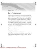
your starting templates. One possible example of graphic style in a CD phase of a project done by
BNIM Architects is shown in Figure 4.1.
44831.book Page 81 Friday, October 12, 2007 12:31 AM
Please purchase PDF Split-Merge on www.verypdf.com to remove this watermark.
82
CHAPTER 4
SETTING UP YOUR TEMPLATES AND OFFICE STANDARDS
Figure 4.1
Example of stylized
annotations used in a
custom template
With Revit, you can expect to set up your templates by doing one or more of the following:
◆
Defining all the project settings to meet your graphic requirements
◆
Preloading model and annotation elements
◆
Defining system families before you start a project
Once everything is in place, you can then save the file as a template (
.rte
) and use that template
whenever you start a new project. Once you’ve saved a new template, you can have Revit open that
template by default by setting options in the File Locations dialog. Follow these steps:
Choose Settings
Options, and click the File Locations tab.
The first option in the dialog shows the default template location. Click the Browse button to
choose a new path to your default template (Figure 4.2).
Figure 4.2
Change the path
to your default
template once you’ve
made one.
44831.book Page 82 Friday, October 12, 2007 12:31 AM
Please purchase PDF Split-Merge on www.verypdf.com to remove this watermark.
STARTING A PROJECT WITH A CUSTOM TEMPLATE
83
Creating and reusing templates can increase your productivity and keep your documentation
looking consistent. Specifically, using templates allows you to do the following:
◆
Reuse work that you’ve already created whenever you can
◆
Maintain consistency in a project, especially when many team members participate in its cre-
ation
◆
Assure graphic consistency across projects
In this chapter, we focus on personalizing (customizing) the Revit template file (
.rte
). The
following list lays out items we suggest you go through one by one when setting up templates. This
doesn’t represent
all
possible settings you can predefine in a template, but it includes those that we
think are most pertinent:
Settings for graphics:
◆
Object styles
◆
Materials
◆
Line styles
◆
Line patterns
◆
Fill patterns (hatches)
◆
View templates
Setting up annotations:
◆
Dimension styles
◆
Text styles
◆
View tags
◆
Annotation tags
Setting up title blocks
Setting up global project settings:
◆
Keynoting external file locations
◆
Project units
Strategies for Making Templates
Different architectural firms address template files in one of two ways: generic, one-size-fits-all
office templates; or project-type–specific templates. Some companies focus on one type of building
(healthcare, office, retail, and so on) where a single template is sufficient, and others do a wide
range of projects and may even work across cultures with very different requirements between
project types. If you work all over the globe or have many types of projects, then a generic office
template probably isn’t the best strategy. Instead, create new templates for each type of project. On
the other hand, if you’re focused on predictable, similar projects, you can start each project from
one template.
44831.book Page 83 Friday, October 12, 2007 12:31 AM
Please purchase PDF Split-Merge on www.verypdf.com to remove this watermark.
84
CHAPTER 4
SETTING UP YOUR TEMPLATES AND OFFICE STANDARDS
Don’t overburden your template with too many elements—especially if you don’t intend to use them
all. You’ll experience better performance when launching Revit and reduce the file size footprint of your
model by starting out with a lean template.
When creating your own personalized template, avoid starting from an empty file (No Template); use an
existing RTE file. You’ll save yourself a lot of time by doing this.
Settings for Graphic Consistency
One of the goals of using a template is to assure graphic consistency across a project or even across
Office. To achieve that, you need to set up the object styles that control the graphic appearance of
your Revit elements as well as drafting elements such as lines, line and hatch Patterns, materials,
and so on.
Object Styles
As we mentioned in Chapter 2, the Object Styles dialog controls the graphics for all the categories
in your project. To access the dialog, choose Settings
Object Styles. This dialog has three tabs:
Model Objects, Annotation Objects, and Imported Objects. In this section, we’ll discuss the first two
types of objects. (Under the Tab for Imported objects is where all DWG, DXF, or DGN files that you
have imported in your Revit file appear. These file types are based on a layering system. Revit
doesn’t work with layers, however it can read layers from imported files and classifies them in the
Revit project as subcategories which can be controlled graphically similar to the way we control
model and annotation categories.
When you define a template, you should focus on the first two tabs: Model and Annotation Objects.
They’re organized in a similar way: They list all main categories and their subcategories in a tree
structure. You can define different graphics for the main category as opposed to its subcategory. If
we take a door family as an example, you can define different graphic settings for the panel, the
frame, and the door swing. The settings on these tabs are as follows:
Model Objects
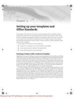
As shown in Figure 4.3, six columns are used to control graphic properties of
model elements. The first holds the list of all available categories and their subcategories of model
elements in Revit.
The next two columns define the line weight that will be used when these elements are drawn
in projection (elevation and 3D) or section (plan or section) view. In some of the categories,
you’ll notice that the Cut column is grayed out; this is typical for elements that are never cut by
Revit. The line weight used in these columns can vary between 1 and 16.
The next two columns define the color and pattern of the lines used to draw the geometry of
these elements. The last column on the right lets you define a default material that will be asso-
ciated with the category or subcategory in the event that elements in that category don’t have
materials explicitly defined. In an element, if you set the material to By Category, it looks to the
material set in the Object Styles dialog.
Annotation Objects
This tab is similar to the Model Objects tab. The difference lies in the
material definition (lines don’t have materials!) and the line weight (there is no distinguishing
between projection and cut line weight), because annotation objects are 2D only.
44831.book Page 84 Friday, October 12, 2007 12:31 AM
Please purchase PDF Split-Merge on www.verypdf.com to remove this watermark.
SETTINGS FOR GRAPHIC CONSISTENCY
85
Figure 4.3
The Object Styles
dialog gives you
independent graphic
control of all Revit
categories and
subcategories.
All these settings may look like overkill at first, but you usually only need to set up these values
at the beginning of a process when building your office templates. Once you’ve assigned all the
desired line weights, colors, and materials, you shouldn’t mess around with them, because the
effect will be global. While Object Styles are global, you do have the ability to change the graphic
style of any element for a specific view, using overrides (View
Visibility Graphic Overrides).
Object styles allow you to establish the graphical standard for the drawings that leave your
office, contributing to an appearance of professionalism; take your time, and invest in getting them
right. These powerful settings shouldn’t scare you; they will make sure that your drawings have a
consistent look and feel.
Line Styles
A line style is composed of a
line weight
,
line color,
and
line pattern
. To access the line styles, choose
Settings
Line Styles.
The dialog that opens (Figure 4.4) has four columns to control the appearance of each
line type.
The Category column is organized in a tree structure with all line styles listed as subcategories
of lines. As you can see, each style is defined by Line Weight, Line Color, and Line Pattern. Line
Weight can have a value between 1 and 16, corresponding to a physical pen thickness that varies
slightly based on view scale. This is the actual thickness of the line when printed on paper at
100 percent. Notice that lines have different thickness as you zoom in and out of a view, indicating
that the lines have a real thickness.
line weights are managed from the Settings
Line Weights dialog (Figure 4.5). As the scale gets
coarser, line weights adjust so the drawing is still readable. For example, notice how the line thick-
ness varies for heavy pens between scales.
44831.book Page 85 Friday, October 12, 2007 12:31 AM
Please purchase PDF Split-Merge on www.verypdf.com to remove this watermark.
86
CHAPTER 4
SETTING UP YOUR TEMPLATES AND OFFICE STANDARDS
Figure 4.4
The line styles define
weight, color, and
pattern for all lines
used in a project.
Figure 4.5
Model line weights
vary depending on the
view scale.
Back in the Line Styles dialog, notice that some of the line style names are bracketed, but others
aren’t. The bracketed line styles are internal, permanent types of lines, which can’t be renamed or
deleted. Any unbracketed line style can be renamed or deleted at any time. When deleting a line
style that was already used by Revit elements in the project, those elements cannot reference that
line style anymore and will automatically reference the first line style that was above the deleted
one in the Line Style dialog. This may create undesirable results, so you should be aware how lines
update.
To create a new line style,
click the New button in the Modify Subcategories group. Enter a new
name in the dialog that opens, and confirm it by clicking OK. The new style appears in the tree
structure on the left; you can now set the rest of the parameters (Line Weight, Line Color, and Line
Pattern) to suit your needs.
44831.book Page 86 Friday, October 12, 2007 12:31 AM
Please purchase PDF Split-Merge on www.verypdf.com to remove this watermark.
SETTINGS FOR GRAPHIC CONSISTENCY
87
Line Patterns
A
line pattern
is a repetitive series of line segments, spaces, and/or points. To create a new line pat-
tern, choose Settings
Line Patterns. The dialog displays a list of existing line patterns in the project.
On the right side of the dialog are four buttons: New, Edit, Delete, and Rename (see Figure 4.6).
Figure 4.6
Line patterns are
made of dashes,
spaces, and/or dots.
The dialog is fairly simple: To edit an existing line, click the Edit button. To create a new line
pattern, click New. You can then create a line pattern by specifying line and space lengths that form
a repeating sequence. To rename a pattern, click Rename. Be careful when naming line patterns: If
you give a line pattern a name that already exists in the list, Revit overrides the existing pattern
with the new one and overrides all elements that use that line pattern.
A pattern sequence can contain line segments, points, and spaces. For line segments and the
spaces, you need to define their length; for points, a value isn’t necessary. The construction of a
sequence is simple: In the Type column, you select Dash or Dot from the drop-down list; and in the
Value column, you provide a length (if it’s a dash or space). For each row you add, only the avail-
able choices are shown in the drop-down list. Notice that in the first row, the drop-down only offers
Dash and Dot as options, because Revit doesn’t accept a sequence that begins with a space. Follow-
ing the same logic, you can’t have a dot after a dash or the opposite, because they will merge and
the result won’t graphically read.
Before deleting any line pattern, you must verify that it hasn’t been used anywhere in your project.
If you fail to do so, you’ll lose information used and needed elsewhere in the project. This can only be
done manually by checking line patterns used in the Visibility/Graphic Overrides dialog.
Creating a New Line Pattern
Follow these steps to create a new line pattern:
1.
Choose Settings
Line Patterns.
2.
In the Line Pattern dialog, click New.
3.
Give the new line pattern a name.
4.
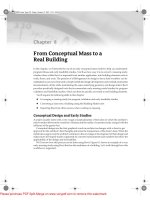
Define the sequence, as shown in Figure 4.7.
5.
Confirm by clicking OK.
44831.book Page 87 Friday, October 12, 2007 12:31 AM
Please purchase PDF Split-Merge on www.verypdf.com to remove this watermark.
88
CHAPTER 4
SETTING UP YOUR TEMPLATES AND OFFICE STANDARDS
6.
The resulting line pattern looks like this:
Figure 4.7
Make a new pattern
using this sample as
a guide.
Materials
Defining materials in your project template is definitely something you shouldn’t neglect. Materials
are essential for the graphical behavior of elements, and they merge with other materials when
elements are joined. For example, concrete walls join and appear contiguous with concrete floors
when the elements’ geometry is joined together. A material also defines how an element’s surface
looks in shaded views, when cut in plan/section, and when seen in 3D and elevation views. In
Figure 4.8, the surface patterns and colors are all derived from the material they’re assigned to.
To access the Materials Editor, choose Menu Settings
Materials. You’ll see the dialog shown
in Figure 4.9.
The Materials Editor has two components: a list and a tabbed properties interface. On the left is
a list of all available Revit materials in the project. Below the list are options to duplicate, rename,
and delete materials:
Duplicate
Use this button each time you need to create a new material. As with most elements you
want to customize in Revit, always duplicate a material before you change any of its properties—if
you fail to do so, you may change a material definition already used in the project and risk losing
a lot of work. To create a new material, find an existing material that closely matches what you
want to make. Once you click the Duplicate button, you’ll be prompted to provide a name for
the newly created material.
Rename
This works like all other Rename buttons in Revit. Clicking the button lets you rename the
material. If you use a name that’s not unique, Revit will warn you and prompt for a unique name.
Delete
You’ll rarely delete an existing material. If for some reason you decide to do so, select
the material that you wish to delete, and click the Delete button. You’ll need to click OK to finalize the
deletion. Be sure you don’t delete a material that is already being used by elements.
44831.book Page 88 Friday, October 12, 2007 12:31 AM
Please purchase PDF Split-Merge on www.verypdf.com to remove this watermark.
SETTINGS FOR GRAPHIC CONSISTENCY
89
Figure 4.8
Materials define the
surface and cut
patterns, color and
render material of
the elements.
Figure 4.9
Use the Materials
Editor to create the
hatch patterns on
elements.
Surface Patterns
Surface Color
44831.book Page 89 Friday, October 12, 2007 12:31 AM
Please purchase PDF Split-Merge on www.verypdf.com to remove this watermark.
90
CHAPTER 4
SETTING UP YOUR TEMPLATES AND OFFICE STANDARDS
On the right side of the editor are three tabs that contain material properties:
◆
Appearance
—Defines graphical and rendering attributes
◆
Physical
—Defines structural properties of a material (used for structural analysis)
◆
Identity
—Defines schedule values and keynotes
We’ll concentrate on the Appearance tab, because it includes the graphical properties of mate-
rials. The other tabs are used for scheduling and structural analysis and aren’t critical to this chapter.
Here are the Appearance tab’s options:
Shading
In this group, you define the color used for the selected material when a view is set
to Shaded or Shaded with Edges display mode. Note that the color can be dependent on the
associated texture. (See the next description.) In that case, the option “Update when AccuRender
selection occurs” is checked, and the dominant color of the texture is displayed as color in
shaded views.
AccuRender
In this group, you select an AccuRender (rendering) texture to be used when that
element is rendered. There are various methods to create your own materials (from a bitmap or
procedural materials). We’ll get into rendering in more detail in Chapter 12.
Surface Pattern
In this group, you select a model pattern that will be displayed on the faces of
the elements in elevation, plan, and 3D views.
Cut Pattern
The fill pattern that you select here is a drafting pattern, and it will be the pattern
displayed when an element is cut through. Some Revit elements can’t be cut, as we discussed in
Chapter 2; in these cases, this parameter has no effect on the graphic display.
It may seem impossible to imagine all the materials you’ll need in a project, making building a
template seem daunting. Think of the basic materials you’re likely to use: woods, brick, concrete,
glass, and so on, and build from those. Remember, a template is just a starting point, and you can
always expand it. If you end up making a lot of nice materials over the course of a project, use
Transfer Project Standards functionality to move materials back into your template(s).
Fill Patterns (Hatch)
Materials are often represented with simple hatch patterns. For any material used in Revit, you can
define a
surface pattern
and a
cut pattern
. For simple parallel hatches and crosshatches, you can use
the patterns already supplied in Revit or you can also make your own custom hatches. For more
complex patterns, you need to import an external pattern file (
.pat
). To access the Fill Pattern
settings, choose Settings
Fill Patterns (see Figure 4.10). On the left side of the Fill Patterns dialog,
you can view the names and small graphic previews of the patterns that help you visualize as you
select and edit the patterns. Below those are the Pattern Type options, where you choose what type
of patterns you wish to create or inform you what type is the pattern you wish to edit (drafting or
model). Similar to the Line Styles dialog, the New, Edit, and Delete buttons appear on the right.
There are two types of fill patterns:
model patterns
and
drafting patterns
. Use the model patterns
when you want to convey real-world dimensional patterns to represent a material. Use drafting
patterns for symbolic representations. For example, a model pattern is used to show a brick pattern
in 3D and elevation views, whereas a drafting brick pattern is used to represent the cut pattern in
plan and section. Figure 4.11 shows how concrete masonry units (CMUs) are represented with a
running bond pattern (model) as well as a crosshatch (drafting).
44831.book Page 90 Friday, October 12, 2007 12:31 AM
Please purchase PDF Split-Merge on www.verypdf.com to remove this watermark.
SETTINGS FOR GRAPHIC CONSISTENCY
91
Figure 4.10
Fill patterns are
defined separately for
drafting and model
representations.
Figure 4.11
The CMU wall has
both a drafting
pattern (cut) and
a model pattern
(surface) defined.
Model and drafting patterns have specific behaviors. In our example, we have a CMU wall with
blocks that measure 16˝
×
8˝ (40mm x 20mm), regardless of the view scale. With a drafting pattern,
the opposite is true: The pattern adjusts with the view scale so the pattern looks identical in all
scales.
To create a new pattern, first choose either Model or Drafting, and then click the New button. A
generic pattern appears in the New Pattern dialog. You can then design your pattern and assign
some behaviors.
Cut Pattern
Surface Pattern
44831.book Page 91 Friday, October 12, 2007 12:31 AM
Please purchase PDF Split-Merge on www.verypdf.com to remove this watermark.
92
CHAPTER 4
SETTING UP YOUR TEMPLATES AND OFFICE STANDARDS
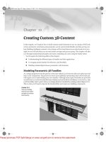
Figure 4.12
From left to right:
pattern orientation
Orient To View, Keep
Readable, and Align
With Element
The option to Orient In Host Layers is particularly useful when you’re making drafting patterns.
This allows you to specify how a pattern orients itself relative to host elements such as walls, floors,
roofs, and ceilings when they’re represented as cut. (Note that the option isn’t available for model
pattern types.)
The three options shown in Figure 4.12 are described here:
Orient To View
When this orientation is applied, the patters used in the project all have the
same orientation and the same origin. They’re always perfectly aligned with the origin of
the view.
Keep Readable
This orientation is best understood when compared with the Keep Readable
attribute of text that is always readable regardless of its orientation.
Align With Element
This orientation ensures that the pattern orientation depends on the ori-
entation of the host element. Patterns essentially run parallel with the element.
You can choose to make either simple or custom patterns with this dialog, using the radio button
options. Figure 4.13 shows the result of each option:
Simple
These patterns are generated with parallel or crosshatch lines that can have different
angles and spacing. With both the crosshatch and parallel options, you can specify only one
angle for the entire pattern. Using crosshatch, you can set two spacing values. The exercise in the
sidebar “Creating a Simple Fill Pattern” demonstrates creating a fill pattern.
Custom
This pattern requires you to import a pattern from an external source. This is often
necessary due to Revit’s limited customization of pattern functionality. Your office may have a
set of established patterns they’ve been using for years, and this allows you to import those
without having to make new patterns from scratch. Custom patterns let you import a PAT file
from anywhere on your hard drive or on a network and use it as a base pattern for a new fill pat-
tern in Revit. The next section shows some best practices for importing a PAT file.
Figure 4.13
From left to right:
simple fill
pattern, simple fill
pattern with the cross-
hatch option selected,
and a custom fill
pattern
44831.book Page 92 Friday, October 12, 2007 12:31 AM
Please purchase PDF Split-Merge on www.verypdf.com to remove this watermark.
SETTINGS FOR GRAPHIC CONSISTENCY
93
Creating a Custom Pattern Using a Pattern File (
.pat
)
Custom patterns require an external file that contains the definition of the pattern. The file exten-
sion of that pattern should be
.pat
, which is what you’ll make in this section by editing an existing
AutoCAD PAT file. An advantage of specifying patterns in the template file is that the PAT file
won’t need to be installed on each computer where Revit is installed; Revit stores each pattern
internally, in each project.
Before modifying PAT files, always make a copy of the file you intend to use in Revit; you
don’t want to risk messing up other files that might use that PAT file. PAT files can be edited with
Notepad, but any text-editing application will do. For this exercise, you’ll choose the AutoCAD
pattern called Grass, which you can find in
acadiso.PAT
(in metric units) or
acad.pat
(imperial
units) located in the Chapter 4 folder on the book’s website (
www.sybex.com/go/masteringrevit2008
).
Creating a Simple Fill Pattern
Often, the default templates don’t have all the patterns you need. Following these steps, you can make
a new simple fill pattern:
1.
Choose Settings Fill Patterns.
2.
In the Fill Patterns dialog, choose to make either a Model or a Drafting pattern, and click New.
3.
In the New Pattern dialog, enter a new name for the fill pattern.
4.
If Drafting is selected, also choose an option from the Orientation in Host Layers drop-down.
5.
In the Simple group, enter a line angle. Choosing to create a crosshatched pattern lets you define the
line spacing in both directions of the crosshatch. Note that a crosshatch always makes the second set
of parallel lines perpendicular to the first.
6.
The preview window shows the pattern. Click OK to commit the pattern to the model.
44831.book Page 93 Friday, October 12, 2007 12:31 AM
Please purchase PDF Split-Merge on www.verypdf.com to remove this watermark.
94
CHAPTER 4 SETTING UP YOUR TEMPLATES AND OFFICE STANDARDS
Importing a Custom Pattern
Follow these steps to make a custom fill pattern by importing an existing pattern definition:
1.
Using Notepad, open the file acadiso.PAT or acad.PAT.
2.
Highlight the lines that define the patterns, and select them:
45, 6.35, 0, 4.49013, 4.49013, 1.5875, -5.80526, 1.5875, -8.98026
*GRASS, turfed surface
90, 0, 0, 17.9605, 17.9605, 4.7625, -31.1585
45, 0, 0, 0, 25.4, 4.7625, -20.6375
135, 0, 0, 0, 25.4, 4.7625, -20.6375
*GRATE, grid
0, 0, 0, 0, 0.79375
3.
Choose Edit Copy.
4.
Open a new text file, and paste the selection. (Note that you can also open the PAT file in
which all Revit patterns are already saved. In that case, paste the selected text in that file.)
5.
This is the important part: In the new text file where you pasted the selected text, add the
following lines:
;%UNITS=MM
*GRASS, turfed surface
;%TYPE=DRAFTING
90, 0, 0, 17.9605, 17.9605, 4.7625, -31.1585
45, 0, 0, 0, 25.4, 4.7625, -20.6375
135, 0, 0, 0, 25.4, 4.7625, -20.6375
The first line that you write before the pattern text ;%UNITS=MM, can appear only once in the
text file. It defines the value for the units used in the pattern. In the example, the units are
millimeters (MM); if you wanted to work in imperial units, it would be ;%UNITS=INCH. (If
you followed our second option to not create a new note for each file but collect them in one
file, then this line already exists and you don’t need to add it.)
The second statement, ;%TYPE=DRAFTING, helps define whether you’re creating a drafting or
model pattern. In this example, the pattern is the Drafting type. It’s important to know that
when you import a new pattern, the type of pattern needs to be the same as the new type of
pattern you’re making. In other words, if you’re making a new model pattern, you can’t
import a drafting pattern. If you try to do so, you’ll see a warning message like the one shown
in Figure 4.14.
6.
Save your text file with a .pat file extension.
7.
In Revit, choose Settings Fill Patterns.
8.
In the Fill Patterns dialog, verify that the Drafting option is selected, and click New.
9.
In the New Pattern dialog, select the Custom option. The lower part of the dialog offers new
options.
44831.book Page 94 Friday, October 12, 2007 12:31 AM
Please purchase PDF Split-Merge on www.verypdf.com to remove this watermark.
SETTINGS FOR GRAPHIC CONSISTENCY
95
Figure 4.14
If you try to assign a
drafting .pat pattern
to a Revit model
pattern, you’ll see a
warning.
10.
Click Import.
11.
Navigate to the place on your hard drive or network where you saved the PAT file, and
click Open.
12.
In the list that appears to the right of this button, you can see the name of the pattern you cre-
ated: Grass. (If you have a PAT file with many patterns defined, you see all the other drafting
patterns available in that list.) The name of the pattern automatically becomes the name of
your fill pattern, but you can change that if you like. See Figure 4.15.
Figure 4.15
The New Pattern
dialog displays the
imported PAT file in
the Custom group.
13.
If necessary, you can adjust the scales of the imported pattern. The Preview window displays
the graphic of the pattern, always in 1:1 scale. This informs you if you need to scale the pat-
tern up or down. You’ll know that you need to scale the pattern if the preview appears as a
solid black box—that means the pattern is too dense.
14.
If you’re happy with the result, confirm by clicking OK.
44831.book Page 95 Friday, October 12, 2007 12:31 AM
Please purchase PDF Split-Merge on www.verypdf.com to remove this watermark.
96
CHAPTER 4 SETTING UP YOUR TEMPLATES AND OFFICE STANDARDS
Dimension Styles
Dimension styles are system families used to dimension the model. Dimensions can be linear,
angular, or radial, each of which has a set of type parameters that control their graphic character-
istics. By default, predefined type parameters are set for each of these dimension styles. When plac-
ing dimensions in the project, you can choose between aligned, linear, angular, radial, and arc
length dimensions. Depending on the choice you make, a corresponding dimension style will be
chosen for you:
◆
Aligned, linear, and arc length dimensions are associated with the system family Linear
Dimension Style.
◆
The angular dimensions are associated with the system family Angular Dimension Style.
◆
The Radial dimensions are associated with the system family Radial Dimension Style.
Properties of Dimension Styles
Dimension styles can vary from a rigid technical appearance to more creative and sketchy types.
Figure 4.16 shows three variations of a liner dimension style, each using a different type of tick mark.
The range of graphic controls at your disposal is wide. Most conventions can be achieved using the
options located in the type properties of your dimension types. The options include tick marks,
length of dimension lines, extension, text type, spacing of text, spacing between the text and the
dim line, and so on. Figure 4.17 shows the type properties of a linear dimension.
Let’s look at the various ways you can customize the appearance of dimensions:
Tick Mark This option allows you to select the type of graphic called a tick mark that marks the
crossing between the dimension line and the extension lines. You can select the type of the tick
mark but not its size. Adjusting the size isn’t possible directly from the dimension dialog. To edit
a tick mark or make a new one, choose Settings Annotations Arrow Heads. You’ll see the
Type Properties dialog shown in Figure 4.18.
Figure 4.16
You can create a variety
of graphical dimen-
sion styles with Revit.
44831.book Page 96 Friday, October 12, 2007 12:31 AM
Please purchase PDF Split-Merge on www.verypdf.com to remove this watermark.
SETTINGS FOR GRAPHIC CONSISTENCY
97
Figure 4.17
Type properties are
used to define different
graphic styles for
dimensions.
Figure 4.18
Type Properties of a
tick mark
44831.book Page 97 Friday, October 12, 2007 12:31 AM
Please purchase PDF Split-Merge on www.verypdf.com to remove this watermark.
98
CHAPTER 4 SETTING UP YOUR TEMPLATES AND OFFICE STANDARDS
Line Weight This sets the thickness of the line that represents the dimension line and can
be any value from 1 to 16. These numbers correspond to the weights defined in the Settings
line weights Annotation line weights dialog.
Tick Mark Line Weight You can set the thickness of the tick mark to any value from 1 to 16.
Dimension Line Extension This setting allows you to define the length of the extension of
the dimension line beyond the tick mark. In this example, the line extension has been highlighted
in bold:
Flipped Dimension Line Extension This setting is grayed out unless Tick Mark is set to Arrow
Head. It inverts the direction of the arrows when the space between them is too small to accom-
modate both arrows in the dimension space. This parameter controls the length of the extension
of the dimension line after the arrow symbol.
Witness Line Control This setting controls the position of the witness lines with respect to the
element that is dimensioned. You can choose one of the following options: Gap to Element or
Fixed to Dimension Line.
Witness Line Length This parameter defines the length of the witness line. It’s active only
when Witness Line Control is set to Fixed to Dimension Line.
Witness Line Gap to Element This parameter sets the distance between the element that is
dimensioned and the witness line. It’s active only when Witness Line Control is set to Gap to
Element.
Witness Line Extension This parameter controls the length of the witness line above the
dimension line.
Centerline Symbol Some local standards require a specific graphic representation of the
dimensions that reference to center axis of an element. By loading custom annotation symbol
families into your project, you’ll be able to choose which one is best suited for your needs.
Centerline Pattern Using this parameter, you can define a line style when you’re dimension-
ing to the center axis of an element. Again, this is to accommodate various local standards that
require the center of elements to be graphically different from other dimensions.
44831.book Page 98 Friday, October 12, 2007 12:31 AM
Please purchase PDF Split-Merge on www.verypdf.com to remove this watermark.