Báo cáo hóa học: " Conductance of Graphene Nanoribbon Junctions and the Tight Binding Model" pptx
Bạn đang xem bản rút gọn của tài liệu. Xem và tải ngay bản đầy đủ của tài liệu tại đây (291.16 KB, 5 trang )
NANO EXPRESS Open Access
Conductance of Graphene Nanoribbon Junctions
and the Tight Binding Model
Y Wu, PA Childs
*
Abstract
Planar carbon-based electronic devices, including metal/semiconductor junctions, transistors and interconnects, can
now be formed from patterned sheets of graphene. Most simulations of charge transport within graphene-based
electronic devices assume an energy band structure based on a nearest-neighbour tight binding analysis. In this
paper, the energy band structure and conductance of graphene nanoribbons and metal/semiconductor junctions
are obtained using a third nearest-neighbour tight binding analysis in conjunction with an efficient nonequilibrium
Green’s function formalism. We find significant differences in both the energy band structure and conducta nce
obtained with the two approximations.
Introduction
Since the repo rt of the preparation of graphene by
Novoselov et al. [1] in 2004, there has been an enormous
and rapid growth in interest in the material. Of all the
all otropes of carbo n, graphene is of particul ar interest to
the semiconductor industry as it is compatible with pla-
nar technology. Although graphene is metallic, it can be
tailored to form semiconducting nanoribbons, junctions
and circuits by lithographic techniques. Simulations of
charge transport within devices based on this n ew tech-
nology exploit established techniques for low dimen-
sional structures [2,3]. The current flowing through a
semiconducting nanoribbon formed between two metal-
lic contacts has been established using a nonequilibrium
Green’s Function (NEGF) formalism based coupled with
an energy band structure d erived using a tight binding
Hamiltonian [4-7]. To minimise computation time, the
nearest-neighbour tight bi nding approximation is com-
monly used to determine the energy states and overlap is
ignored. This assumption has also been used for calculat-
ing the energy states of other carbon-based materials
such as car bon nanotubes [8] and carbon nanocones [9].
Recently, Reich et al. [10] have demonstrated that this
approximation is o nly valid close to the K points, and a
tight binding approach including up to third nearest-
neighbours gives a better approximation to the energy
dispersion over the entire Brillouin zone.
In this paper, we simulate charge transport in a gra-
phene nanoribbon and a nanoribbon junction using a
NEGF based on a third nearest-neighbour tight binding
energy dispersion. For transport studies in nanoribbons
and junctions, the formulation of the problem differs
from that required for bulk graphene. Third nearest-
neighbour interactions introduce additional exchange
and overlap integrals significantly modifying the Gr een’s
function. Calculation of device characteristi cs is facili-
tated by the inclusion of a Sancho-Rubio [11] iterative
scheme, modified by the inclusion of third nearest-
neighbour interactions, for the calculation of the self-
energies. We find that the conductance is significantly
alteredcomparedwiththatobtainedbasedonthe
nearest-neighbour tight binding dispersion even in an
isolated nanoribbon. Hong et al. [12] observed that the
conductance is modified (increased as well as decreased)
by the pre sence of defects within the lattice. Our results
show that details of the band structure can significantly
modify the observed conductivities when defects are
included in the structure.
Theory
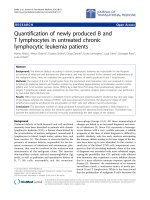
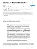
The basis for our analysis is the hexagonal graphene lat-
tice shown in Figure 1. a
1
and b
1
are the principal vec-
tors of the unit cell containing two carbon atoms
belonging to the two sub-lattices. Atoms on the con-
centric circles of increasing radius correspond to the
nearest-neighbours, second nearest-neighbours and third
nearest-neighbours, respectively.
* Correspondence:
School of Electronic, Electrical and Computer Engineering, University of
Birmingham, B15 2TT, Birmingham, UK.
Wu and Childs Nanoscale Res Lett 2011, 6:62
/>© 2010 Wu and Childs. This is an Open Access article distributed under the terms of the Creative Commons Attribution License
(http://creativecommo ns.org/licenses/by/2.0), which permits unrestricted use, distribution, and reproduction in any medium, provided
the original wo rk is properly cited.
Saito et al. [8] d erived the dispersion relation below
using a nearest-neighbour tight binding a nalysis includ-
ing the overlap integral s
0
.
E
f
sf
p
±
=()
()
()
k
k
k
20
0
1
(1)
Here, f (k)=3+2cosk · a
1
+2 cos k · b
1
+2cosk ·
(a
1
- b
1
) and the parameters, ε
2p
, g
0
and s
0
are obtained
by fitting to experimental results or ab initio calculations.
Most analyses of charge transport in graphene-based
structures simplify the result further by ignoring s
0
. Reich
et al. [10] derived the dispersion relation for graphene
based on third nearest-neighbours. In this work, the
energy band structure of a graphene nanoribbon includ-
ing third nearest-neighbour interactions is obtained from
the block Hamiltonian and overlap matrices given below
for the unit cell defined by the rectangle in Figure 1.
E
SS
SSS
SS
nn nn nn
NN NN
n
00 01
11
1
0
,,
,,,
,,
−+
−
⎡
⎣
⎢
⎢
⎢
⎢
⎢
⎢
⎤
⎦
⎥
⎥
⎥
⎥
⎥
⎥
N
nn nn nn
NN NN
HH
HHH
HH
⎡
⎣
⎢
⎢
⎢
⎢
⎢
⎢
⎤
⎦
⎥
⎥
⎥
⎥
⎥
⎥
=
⎡
−+
−
00 01
11
1
,,
,,,
,,
⎣⎣
⎢
⎢
⎢
⎢
⎢
⎢
⎤
⎦
⎥
⎥
⎥
⎥
⎥
⎥
⎡
⎣
⎢
⎢
⎢
⎢
⎢
⎢
⎤
⎦
⎥
⎥
⎥
⎥
⎥
⎥
0
n
N
(2)
For the nth row of the above equation, we have
HHH
ES S S
nn n nn n nn n
nn n nn n nn n
,,,
,,,
(
−− ++
−− ++
++
−++
11 11
11 1
11
0) =
(3)
Considering the energy dispersion in the direction o f
charge transport, the Bloch form of the wavefunction
ensures that
n
~e
ikn
. Substitution of
n
into the above
equation yields the secular equation
det[
()
,,,
,,,
HHH
ES S S
nn
k
nn nn
k
nn
k
nn nn
k
−
−
+
−
−
+
++
−++
11
11
ee
ee
ii
ii
]] = 0
(4)
In the case of first nearest approximation without
orbital overlap, S
n,n-1
and S
n,n+1
are e mpty matrices. To
facilitate comparison with published results, we u se an
armchair-edge with index [13] N =13asourmodel
nanoribbon. In the paper by Reich, tight binding para-
meters were obtained by fitting the band structure to
that obtained by ab initio calculations. Recently, Kundo
[14] has reported a set of tight biding parameters based
on fitting to a first principle calculation but more
directly related to the physical quantities of interest.
These parameters have been utilised in our calculation
and are presented below for third nearest-neighbour
interactions (Table 1).
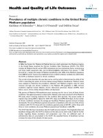
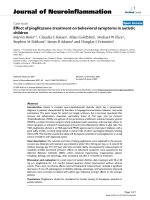
Figure 2 co mpares the ene rgy band st ructure of th e
modelled armchair-edge graphene nanoribbon obtained
from the first nearest-neighbour tight binding method
with that obtained by including up to third nearest-
neighbours. Agreement is reasonable close to the K point
but significant discrepancies occur at higher energies.
Conductance of Graphene Nanoribbons and
Junctions
Conductance in graphene nanoribbons and metal/semi-
conductor junctions is determined using an efficient
nonequilibrium Green’s function formalism described
by Li and Lu [15]. The retarded Green’sfunctionis
given by
GESH
LR
=−−−
+−
[]ΣΣ
1
(5)
Here, E
+
= E +ih an d h is a small positive energy
value (10
-5
eV in this simulation) which circumvents the
singular point of the matrix inversion [16]. H is a tight
binding Hamiltonian matrix including up to third near-
est-neighbours, and S is the overlap matrix. Open
Figure 1 Armchair-edgegraphenemetal(indexN =23)/
semiconductor (index N = 13) junction. The rectangle shows the
semiconductor unit cell, and the concentric circles of increasing
radius show first, second and third nearest-neighbours, respectively.
Table 1 Tight binding parameters [14]
Neighbours E
2
p(eV) g
0
(eV) g
1
(eV) g
2
(eV) s
0
s
1
s
2
3rd-nearest -0.45 -2.78 -0.15 -0.095 0.117 0.004 0.002
Wu and Childs Nanoscale Res Lett 2011, 6:62
/>Page 2 of 5
boundary conditions are included through the left and
right self-energy matrix elements, Σ
L.R
. The self-energies
are independently evaluated through an iterative scheme
describedbySanchoetal.[11],modifiedtoinclude
third nearest-neighbour interactions. Determination of
the retarded Green’s function through equation 5 is
facilitated by the inclusion of the body of the device in
the right-hand contact through the recursive scheme
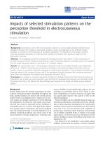
described in ref. [15]. We will now outline the numeri-
cal procedure for deriving the conductance with third
nearest-neighbour interactions included. Figure 3 sho ws
a schematic of the unit cell labelling used to formulate
the Green’s function.
We calculate the surface retarded Green’s functions of
the left and right leads by
gESHESH
L
00 00 00 0 1 0 1
1
,,,,,
[()]=−− −
++
−−
−
(6)
gESHESH
MM
R
++
++
−−
−
=−− −
1 1 00 00 10 10
1
,,,,,
[()]
(7)
where θ and
are the appropriate transfer matrices
calculated from the following iterative procedure.
=+ + ++tt t tttt ttt
n01 2001 012
(8)
=+ + ++tt t tttt ttt
n01 2001 012
(9)
where t
i
and
t
i
are defined by
tIt t ttt
ii iiii
=− −
−−
−
−−−
()
11
1
1
2
11
(10)
tItt tt t
iiiiii
=− −
−− −−
−
−
()
11 11
1
1
2
(11)
and
tESH ES H
00000
1
01 01
=− −
+−+
−−
()( )
,, , ,
(12)
tESH ES H
00000
1
10 10
=− −
+−+
−−
()( )
,, , ,
(13)
The process is repeated unti l
tt
00
<
with δ arbitra-
rily small. The nonzero elements of the self-energies
Σ
11,
L
and
Σ
MM
R
,
can be then obtained by
Σ
11 10 10 00 01 01,,,,,,
()()
LR
ES H g ES H=− −
++
(14)
Σ
MM
R
MM
R
ES H g ES H
,,,,,,
()()=− −
+
++
+
01 01 1 1 10 10
(15)
The conductance is obtained from the relation
GE
e
h
TE() ()=
2
2
(16)
where the transmission coefficient is obtained from
TE Tr G G
LR
()
= [],ΓΓ
†
(17)
with Γ
L,R
= i[Σ
L,R
-(Σ
L,R
)
†
].
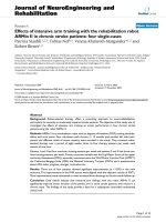
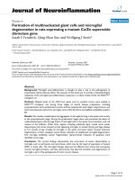
Figure 4a, b compares the conductan ce of a graphene
armchair-edge nanoribbon of index N = 13 and metal/
semiconductor junction fo rmed with the nanoribbon
-3 -2 -1 0 1 2 3
-2
-1.5
-1
-0.5
0
0.5
1
1.5
2
(a) (b)
Ka
Energy E (eV)
-3 -2 -1 0 1 2 3
-2
-1.5
-1
-0.5
0
0.5
1
1.5
2
Ka
Energy E (eV)
Figure 2 Energy band structure of an N = 13 armchair graphene nanoribbon, a obtai ned from the first nearest-neighbour
tight binding method and b including third nearest-neighbours.
Figure 3 Schematic showing the unit cell labelling used to
formulate the Green’s function.
Wu and Childs Nanoscale Res Lett 2011, 6:62
/>Page 3 of 5
ass uming first and third nearest-neighbour interactions,
respectively. For graphene nanoribbons, differences are
observed in the step-like structur e, reflecting differences
in the calculated band structure. When only first
nearest-neighbour interactions are considered, the con-
ductance of the conduction and valence bands is always
symmetrical as determined by the formulation of the
energy dispersion relation, equation 1. In the case of
graphene nanoribbons, the conductance within a few
electron volts of the Fermi energy is symmetrical for
both first and third nearest-neighbour interactions.
However, it is notable that at higher energies, overlap
integrals introduced by third nearest-neighbour interac-
tions result in asymmetry between the conductance in
the conduction and valence bands. For metal/semicon-
ductor junctions, significant differences in conductivity
occur even at low energies due to mismatches of the
sub-bands. Asymmetry in the conduc tion and valence
band conductance ( absent for first nearest-neighbour
interactions) is also apparent when third nearest-
neighbour interactions are included in the Green’s
function. Differences are also seen when defects are
incorporated within a metal/semiconductor junction, an
interesting system explored by Hong et.al. [12]. In this
work, vacancies are introduced in the lattice at the posi-
tions marked by the solid rectangle and triangle in
Figure 1 and the conductance obtained in each case.
Hong et al. derive a coupling term associated with dif-
ferences in band struct ure. For third neare st-neighbour,
the solution to the coupling streng th must be der ived
numerically.
Conclusions
In this paper, we have determined the energy band
structure of graphene nanoribbons and conductance of
nanoribbons and graphene metal/semiconductor
junctions using a NEGF f ormalism based on the tight
binding method approximated to first nearest-neighbour
and third nearest-neighbour. Significant differences are
observed, suggesting the commonly used first nearest-
neighbour approximation may not be sufficiently
accurate in some circumstances. The most notable dif-
ferences are observed when defects are introduced in
the metal/semiconductor junctions.
Received: 9 July 2010 Accepted: 9 September 2010
Published: 7 October 2010
References
1. Novoselov KS, et al: Two-dimensional gas of massless Dirac fermions in
graphene. Nature 2005, 438:197-200.
2. Cresti A, et al: Charge transport in disordered graphene-based low
dimensional materials. Nano Res 2008, 1:361-394.
3. Neto A, et al: The electronic properties of graphene. Rev Mod Phys 2009,
81:109-162.
4. Golizadeh-Mojarad R, et al: Atomistic non-equilibrium Green’s function
simulations of Graphene nano-ribbons in the quantum hall regime.
J Comput Electron 2008, 7:407-410.
5. Liang G, et al: Ballistic graphene nanoribbon metal-oxide-semiconductor
field-effect transistors: a full real-space quantum transport simulation.
J Appl Phys 2007, 102:054307.
6. Zhao P, Guo J: Modeling edge effects in graphene nanoribbon field-
effect transistors with real and mode space methods. J Appl Phys 2009,
105:4503.
7. Odili D, et al: Modeling charge transport in graphene nanoribbons and
carbon nanotubes using a Schrödinger-Poisson solver. J Appl Phys 2009,
106:024509.
8. Saito R, et al: Physical Properties of Carbon Nanotubes. Imperial College
Press, London; 1998.
9. Chen J, et al: Low-energy electronic states of carbon nanocones in an
electric field. Nano Micro Lett 2010, 2:121-125.
10. Reich S, et al: Tight-binding description of graphene. Phys Rev B 2002,
66:035412.
11. Sancho M, et al: Quick iterative scheme for the calculation of transfer
matrices: application to Mo (100). J Phys F: Metal Phys 1984, 14:1205-1215.
12. Hong S, et al: Metal-semiconductor junction of graphene nanoribbons.
Appl Phys Lett 2008, 92:083107.
13. Nakada K,
et al: Edge state in graphene ribbons: nanometer size effect
and edge shape dependence. Phys Rev B 1996, 54:17954-17961.
-1 0 1
0
1
2
3
4
Conductance 2e
2
/h
E
(
eV
)
-1 0 1
0
1
2
3
4
Conductance 2e
2
/h
E
(
eV
)
(a) (b)
Figure 4 Conductance vs Energy for the junction shown in Figure 1, a using first nearest-neighbour parameters and b using third
nearest-neighbours parameters. Dotted lines are for N = 13 armchair nanoribbon, solid lines are for ideal metal/semiconductor junctions, dot–
dash lines and dash lines are for junctions with a single defect type A (triangle in Figure 1) and type B (rectangle in Figure 1) respectively.
Wu and Childs Nanoscale Res Lett 2011, 6:62
/>Page 4 of 5
14. Kundu R: Tight binding parameters for graphene. 2009, Arxiv preprint
arXiv:0907.4264.
15. Li TC, Lu S-P: Quantum conductance of graphene nanoribbons with
edge defects. Phys Rev B 2008, 77:085408.
16. Datta S: Quantum Transport: Atom to Transistor Cambridge University Press,
Cambridge; 2005.
doi:10.1007/s11671-010-9791-y
Cite this article as: Wu and Childs: Conductance of Graphene
Nanoribbon Junctions and the Tight Binding Model. Nanoscale Res Lett
2011 6:62.
Submit your manuscript to a
journal and benefi t from:
7 Convenient online submission
7 Rigorous peer review
7 Immediate publication on acceptance
7 Open access: articles freely available online
7 High visibility within the fi eld
7 Retaining the copyright to your article
Submit your next manuscript at 7 springeropen.com
Wu and Childs Nanoscale Res Lett 2011, 6:62
/>Page 5 of 5