Báo cáo hóa học: " Research Article A Fast Network Configuration Algorithm for TDMA Wireless Sensor Networks" pot
Bạn đang xem bản rút gọn của tài liệu. Xem và tải ngay bản đầy đủ của tài liệu tại đây (977.39 KB, 10 trang )
Hindawi Publishing Corporation
EURASIP Journal on Wireless Communications and Networking
Volume 2010, Article ID 513527, 10 pages
doi:10.1155/2010/513527
Research Article
A Fast Network Configuration Algorithm for
TDMA Wireless Sensor Networks
Fernando Royo,
1
Miguel L opez-Guerrero,
2
Teresa Olivares,
1
and Luis Orozco-Barbosa
1
1
Albacete Research Institute of Informatics, University of Castilla-La Mancha (UCLM), 02071-Albacete, Spain
2
Department of Electrical Engineering, Metropolitan Autonomous University-Iztapalapa, 09340 Mexico City, DF, Mexico
Correspondence should be addressed to Fernando Royo,
Received 15 February 2010; Accepted 7 July 2010
Academic Editor: Limin Sun
Copyright © 2010 Fernando Royo et al. This is an open access article distributed under the Creative Commons Attribution License,
which permits unrestricted use, distribution, and reproduction in any medium, provided the original work is properly cited.
The deployment of large-scale wireless sensor networks (WSNs) presents various challenges whose solution requires the design and
development of power-and-time efficient protocols. In this context many proposals and various standards have suggested the use
of time division multiple access (TDMA) in order to guarantee tight-time scheduling and high overall network throughput under
high load conditions. However, in TDMA networks the time and overhead required during the setup phase are major drawbacks
that are often overlooked. In this paper we introduce a simple and robust algorithm specially tailored to be used during the setup
phase of a TDMA-based WSN. The proposed algorithm makes use of 2C, a conflict resolution protocol with some advantageous
properties. As a case study, we consider the setup phase of the synchronous protocol SA-MAC. Our results show that the proposed
algorithm is able to configure highly populated networks in significantly shorter times than traditional CSMA/CA. Furthermore,
an experimental prototype has been developed allowing us to show the feasibility of deploying the proposal using off-the-shelf
components.
1. Introduction
Wireless sensor networks (WSNs) provide a new way of
working for traditional applications such as environmental
monitoring, security, and robotics [1]. The current interest
in these networks is due to the potential number of
applications supported by a large number of small wireless
sensor nodes with some computing capabilities at reduced
cost. However, the battery life of sensor nodes strongly relies
on the development of efficient communication protocols.
These protocols must be based on strategies to minimize
power consumption. In fact, power saving has been the main
driving force behind the development of several protocols
that have recently been introduced in the literature (see
[2] for a recent survey). In this context, the largest energy
savings are achieved by protocols whose communications are
based on time division multiple access (TDMA). In order to
achieve collision-free communications and minimum end-
to-end latency, TDMA communications require a network
configuration phase where all node transmissions must be
scheduled. In this phase all nodes will have to establish
a father-and-child relation in order to create the network
and there will be contention and its related effects such as
collisions and delays. This might be a negligible issue in
networks with a few nodes; but with large and dense WSNs
this problem becomes more relevant. Therefore, network
configuration algorithms must be fast, scalable, and flexible
enough to handle networks of various sizes with no human
intervention.
It is interesting to note that although network config-
uration is a common phase of diverse TDMA-based MAC
protocols, so far the development of fast and efficient setup
algorithms has not been given enough attention.
The work reported in this paper focuses on a proposal
for the efficient setup of TDMA WSNs. At the core of
the protocol there is a conflict resolution algorithm since,
at the network start time, there is no scheduling and
channel access conflicts most likely will arise. To remedy
this problem we can make use of the usual choice for
solving the problem of channel access, that is, the CSMA/CA
algorithm. However, as we will discuss in more detail later,
we believe that this algorithm is not the best solution to this
2 EURASIP Journal on Wireless Communications and Networking
problem. The conflict resolution approach used in this work
is derived from the definition of the two-cell (2C) algorithm
introduced by Paterakis and Papantoni-Kazakos in [3]. The
resulting protocol can be used as the core of the setup phase
in a number of TDMA based protocols. As a case study, we
make use of the SA-MAC protocol, a TDMA synchronous
communication protocol previously introduced in one of
our recent works [4]. Throughout extensive simulation work
we evaluate the performance and operation of our proposal
and show that the 2C-based approach is able to speed up
the network configuration time as compared with solutions
based on traditional CSMA/CA. We also show and verify the
operation of the proposed algorithm using an experimental
setup.
The remainder of this paper is structured as follows.
Section 2 reviews related work in the context of TDMA-
based protocols for WSNs. Section 3 overviews the prin-
ciples on which the present proposal is based. Section 4
describes our proposal using the SA-MAC protocol as a case
study. In Section 5 we describe the simulation results that
we obtained from the performance evaluation. Section 6
describes our experiences from implementing the protocol
in a testbed system. Finally, in Section 7 we provide our
conclusions.
2. Network Setup in TDMA-Based WSNs
TDMA MAC protocols are an appealing approach for
densely populated WSNs. In the context of networks
composed of a large number of power-constrained nodes,
TDMA protocols avoid some important sources of power
wastage, such as idle listening, collisions, and overhearing.
In addition, when an efficient synchronization mechanism
is available, TDMA protocols are able to provide guarantees
for efficient and robust communications [5]. Nevertheless,
the creation of the logical network structure along with the
specific transmission schedule are two issues that remain
as the major challenges during the setup phase of TDMA
protocols.
Nowadays, various approaches are being pursued to
enable the setup phase of TDMA networks. In some
proposals it is assumed that network creation is solved by
using other protocols. For instance, the R-MAC protocol
[6] assumes that a separate protocol, operating during the
setup period, synchronizes the clocks in the sensor nodes
with the required precision. Once the network nodes are
synchronized, R-MAC sends a small control frame along
the data forwarding path to allow all nodes along the path
to learn when to awake in order to receive the data packet
from the immediate upstream node and forward it to the
immediate downstream node.
Other protocols assume that network creation is solved
by means of external hardware. In this category we find
RT-Link [7] which considers that global synchronization
is based on an add-on hardware consisting of a radio
module for synchronization in indoor environments and an
atomic clock receiver for outdoor operation. After detection
of the periodic synchronization signal, the microcontroller
updates its local time. This marks the beginning of a slotted
data communication period. This period is defined as a
fixed-length cycle and it is composed of multiple frames.
Each frame is divided into multiple slots: SS (scheduled
slots, transmit and receive slots) and CS (contention slots,
transmit slots of random access as in slotted aloha). In
the case of a scheduling error, communication is still
possible using contention slots, but nodes in CS do not
have guarantees of successful transmission. This situation
produces loss of information and repetition of the scheduling
phase.
In spite of these efforts, dense networks still pose
significant challenges to network configuration mechanisms.
This is due to the fact that at one time there might be
several nodes trying to join the network. Furthermore,
several nodes may simultaneously reply to join requests
issued by a newly arriving node. As previously mentioned,
arising conflicts during the setup phase can be resolved by
means of the widely known CSMA/CA protocol. In fact, this
mechanism has been included in the specifications of IEEE
802.15.4. However, WSNs require protocols that are fast,
easy to implement, and flexible enough to be used without
modifications across different scenarios. CSMA/CA, on the
other hand, does not meet these requirements mainly due
to the fact that its performance has a strong dependence on
its configuration parameters. For instance, it can be tuned to
save energy by limiting its backoff period, but this policy will
also lead to a large number of collisions in dense networks.
If the backoff window is allowed to grow, this policy will lead
to long idle times and energy waste. Besides, channel access
is not guaranteed.
At this point it is worth mentioning that the problems
previously mentioned have motivated a large number of
clever proposals intended to improve the performance of
CSMA/CA. For instance, Sift is a medium access control
which was introduced in [8]. It makes use of a fixed-
size contention window and nonuniform probabilities for
selecting transmission slots. By reducing the probability of
choosing the first slots, stations selecting these slots most
likely will access the channel without colliding. This is useful
for event-driven WSNs where several nodes may sense the
same event and it is enough to let just a few notification
messages to pass through the network. The performance
evaluation reported in [8] shows that Sift has several
attractive features when compared to standard CSMA/CA.
Other proposals, such as the one described in [9], attempt
to reduce the overall number of collisions by adapting
the success probability according to the collisions observed
in the medium. As a final example we can mention the
CARMA protocol introduced by Garces and Garcia-Luna-
Aceves [10]. This algorithm makes use of a splitting tree
algorithm to resolve collisions and it results in a significant
reduction on the number of collisions. In spite of these and
other efforts, traditional CSMA/CA is the protocol that is
used in real systems such as devices that comply with the
IEEE802.15.4 standard. Due to this reason in this work and,
for comparison purposes, it is the only one that we will
consider.
In the following section we will describe the core of our
proposal for the network configuration phase.
EURASIP Journal on Wireless Communications and Networking 3
3.TheCoreoftheNetwork
Configuration Protocol
In this paper our objective is to introduce a simple, efficient,
and robust network configuration algorithm specifically
designed to be used during the setup phase of TDMA wireless
sensor networks. Such algorithm should provide the means
to quickly solve conflicts arising among nodes attempting to
simultaneously reach a given node. To this end we propose to
develop the collision resolution mechanism based on the 2C
protocol introduced in [3].
The 2C algorithm performs collision resolution by means
of random access. This algorithm considers that time is
slotted and stations are allowed to transmit only at the
beginning of a time slot. A time slot basically equals the
time it takes to transmit a packet and receive a feedback
message from a central station. The feedback message is
binary, that is, it is a collision message C when a collision
was detected and a no collision message NC otherwise. If
only one station transmitted, the corresponding packet will
be successfully transmitted. On the other hand, if there were
several transmission attempts in the same slot, there will be a
collision and its resolution will begin in the following slot.
The collision resolution procedure ends when all stations
that collided successfully transmit their packets. This time
interval is known as a collision resolution interval (CRI). A
station that generates a new transmission request, when a
CRI is in progress, has to wait until the current CRI ends
before attempting channel access. Thus, the 2C algorithm is
able to provide guarantees for fair channel access.
Each station participating in a CRI maintains a counter
that controls its channel access. Let us denote by c
i
the value
of this counter at the beginning of slot i. A station is allowed
to attempt channel access in slot i only when c
i
= 0. Let f
i
be the feedback message corresponding to the transmission
in slot i and received at the end of the same time slot. If
the transmission was unsuccessful, f
i
= C, otherwise the
feedback message is f
i
= NC.
Let us assume that up to the current slot all packets have
been transmitted. Stations with new transmission requests
will set their counter to 0 and will attempt channel access
in the following slot t. Depending on the feedback messages
each station updates its counter as follows:
(i) if c
t
= 1and f
t
= NC, then c
t+1
= 0,
(ii) if c
t
= 1and f
t
= C, then c
t+1
= 1,
(iii) if c
t
= 0and f
t
= C, then c
t+1
will increase to 1 with
probability 0.5.
Regarding the last policy for updating the counter, it is
worth mentioning that in [3] it was proposed to use 0.5
as the probability of increasing the counter to 1 when a
collision was detected. However, it has been shown [11]
that the optimum value for such probability depends on the
actual number of colliding stations. Since the number of
contending nodes is most likely unknown at network start
time, we will use the value of 0.5 in this work. In following
sections we will denote by p
wc
the probability of increasing
the counter after a collision and by p
tc
the probability of not
changing it (with the obvious condition that p
wc
+ p
tc
= 1).
According to the previous description of the 2C algo-
rithm note that, following an NC feedback message, all
stations in the waiting group will attempt to transmit in
the following slot. Therefore, two consecutive NC feedback
messages can only occur at the end of the CRI.
This algorithm is called 2C because contending stations
may be either transmitting or waiting and the two states can
be represented using two cells in a stack. The transmission
cell (TC) represents the group of transmitting stations (i.e.,
c
t
= 0) and the waiting cell (WC) the group of stations that
have deferred transmission (i.e., c
t
= 1).
The 2C algorithm is not tied to any specific transmission
medium so that the original description has to be adapted
to the particularities of wireless communications. In the
original 2C algorithm it is assumed that there is a central
station that is continuously monitoring the channel and
providing feedback messages. However in self-configuring
wireless ad hoc networks it cannot be assumed that there
is such infrastructure in place. In this case the very same
network nodes have to assume this role by monitoring the
transmission medium and reacting accordingly. This issue
leads to a second one. Whereas in wired networks it is
rather easy to detect collisions, in wireless networks this is
not a trivial matter. We propose that, instead of detecting
a collision, the network nodes infer that a collision has
happened. A wireless node can infer that its transmission
has collided if the reply to its request does not arrive. In
this case, and according to the 2C algorithm, a station has
to randomly choose whether to retransmit (i.e., to remain
in the TC) or to enter into the waiting group (WC). When
a successful transmission is sensed, all stations in the WC
enter into the TC and contend again for the channel. No new
stations are allowed to contend until the initial collision is
resolved. Eventually, all stations that collided at the beginning
achieve a successful transmission. We will name this proposal
2C-WSN.
4. Network Configuration in SA-MAC
In this section we describe how 2C-WSN solves the conflicts
arising during the setup phase of a TDMA protocol. Without
loss of generality, we take as a case study the setup phase of
SA-MAC, a TDMA protocol specifically designed for wireless
sensor networks. It is worth emphasizing that the 2C-WSN
mechanism could be easily integrated for solving the conflicts
arising during the setup phase of other TDMA protocols.
4.1. SA-MAC Overview. The main aim of the SA-MAC
protocol is to schedule transmission opportunities in the
network. In the following, the procedure for network con-
figuration will be described by considering one coordinator
node which is responsible of gathering all the data having
been sensed by all the other nodes. In large networks some of
the other nodes may have to act as coordinators thus enabling
the forwarding of collected data to the sink station through
multihop paths.
4 EURASIP Journal on Wireless Communications and Networking
P
A
2
P
A
3
D
A
T
2
D
L
Y
3
D
S
C
2
P
A
3
D
A
T
3
D
A
T
1
P
A
Bs
D
S
C
3
P
A
Bs
D
L
Y
Bs
A
C
K
S
1
A
C
K
S
3
A
C
K
F
Bs
A
C
K
F
Bs
A
C
K
F
3
A
C
K
S
2
D
L
Y
Bs
D
S
C
1
P
A
1
D
S
C
3
D
S
C
1
BS BS
N
3
N
1
N
2
N
3
N
1
N
2
N
1
BS
N
3
N
2
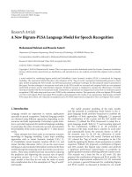
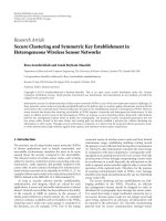
Figure 1: Example of a packet exchange in SA-MAC for the network shown in the upper right corner.
TheSA-MACprotocolmakesuseofthesuperframe
structure defined in the 802.15.4 [12] standard for a beacon-
enabled network. Network beacons are broadcasted by a
coordinator node and they are used to synchronize the
network by signaling the boundaries of superframes. In
multihop networks the beacons are also used to identify a
local coordinator as a possible relay node to the sink station.
Superframes are divided into 16 equally sized slots where
the first one serves as the beacon. The network can enter
into either active or inactive modes. In the inactive mode
the coordinator will not interact with its associated nodes
and may enter in a low-power mode. In the active mode
there are periods for network setup and data transmission.
The setup period is where the network configuration takes
place. To this end, the network nodes exchange three types
of packets, namely, discovery packets (DSC), delay packets
(DLY), and acknowledgement packets (AC K
S
and AC K
F
)to
establish father-and-child relations and to get slot allocations
to be used for data transmission. The exchange of these four
packets forms an atomic operation, from now on referred to
as atomic association operation (AAO). In this work we will
only focus on the setup phase of the protocol, other aspects
of its operation can be consulted in [4].
Let us consider a simple scenario consisting of a coor-
dinator (i.e., the sink node) and a set of nodes within its
transmission range. The coordinator announces its presence
as a parent node, using a PA packet as beacon, so that all other
nodes can start trying to establish a father-and-child relation
with it. All nodes that become aware of the presence of the
coordinator start to broadcast DSC packets. Upon receiving
a DSC packet, the coordinator replies with a DLY packet.
The delay packet indicates the time slot that is assigned for
transmissions from the sensor node to the coordinator. The
node acknowledges the slot allocation with an ACK
S
packet,
and finally the parent node finishes the association procedure
by sending an AC K
F
packet. Once a sensor node ends its
association, it may become a parent node for other nodes.
In order to illustrate the operation of the SA-MAC
protocol in a more complex scenario consider a set of nodes
as illustrated in Figure 1. This scenario consists of a base
station (BS) and nodes N
1
, N
2
,andN
3
. Let us assume that
N
1
and N
3
are located within the coverage area of the BS
and that N
2
is located within the coverage area N
3
but
out of the reach of the BS. Once the BS announces its
presence, using a PA packet as beacon, nodes N
1
and N
3
can start sending DSC packets and collisions may occur
at this time. Thus, a policy has to be implemented in
order to resolve collisions. Let us assume that the collision
resolution protocol lets N
3
successfully transmit its DSC
packet first and in this way it establishes a father-and-
child relation with the BS, completing an AAO. Node N
1
detects the end of the AAO between N
3
and the BS and
it sends its DSC, establishing a father-and-child relation
too.
Nodes that are already part of the network may serve
as coordinators of a new association domain. This process
is initiated when these nodes broadcast their beacon (i.e., a
PA packet). In our example node N
3
starts an association
domain and N
2
is able to use it as a relay node in a route to the
BS. By itself, the beacon scheduling mechanism for multihop
topologies is an important problem [13]; for this work we
assume this problem solved by the time division approach
proposed by the Task Group 15.4b [14].
In order to choose the best parent (i.e., the one with the
lowest hop count to the BS), nodes that want to join the
network can overhear packet exchanges from associations
that take place in their neighbourhood. These packets carry
information about the number of hops to the sink node and
can help other nodes choose the best parent node. At present,
only this parameter has been taken into consideration in the
design.
As nodes get an association to the coordinator node,
they will be assigned guaranteed slots at the end of the
superframe.
EURASIP Journal on Wireless Communications and Networking 5
4.2. Integrating 2C-WSN into the SA-MAC TDMA Protocol.
The overall network setup starts when the coordinator node
is powered on. As previously mentioned, the coordinator
(i.e., sink node or BS) starts the network configuration
by issuing a Parent Available (PA) packet or beacon. The
configuration process requires that the nodes that are already
part of the network offer themselves as local coordinators
by broadcasting PA packets. Other nodes that receive a PA
packet decide whether to select the transmitting node as
their parent node or not by taking into consideration the
reported hop count to the BS. Figure 1 depicts a scenario
and a possible packet exchange that may take place during
the configuration of this network.
From the previous description of SA-MAC operation,
there is one situation when conflicts may arise when the
nodes aiming to join the network attempt to issue their DSC
packets. There is, therefore, a clear need of a reliable and fast
collision resolution protocol to be included into the setup
phase. In the following, we specify the operating mode of the
2C-WSN when used to solve the conflicts during this time
period.
Having detected the presence of a coordinator, two main
outcomes are possible when the nodes attempt to join the
network: (1) only one station broadcasts its DSC packet or
(2) two or more stations broadcast their DSC packets. In
the former case, the coordinator will reply to the requesting
node by issuing a DLY packet completing, after the two
acknowledgement packets, the AAO. In the second case, that
is, several nodes issue their DSC packets during the same
time slot which results in a collision at the coordinator
involving all participating nodes, the nodes involved in the
collision will realize that a collision has resulted since they
will not get any reply from the coordinator node during the
following slot. They will then invoke the 2C-WSN process,
that is to say, each one of them, and independent from each
other, will decide to transmit once again with probability p
tc
or refrain from doing so with probability p
wc
. The nodes
will proceed this way till only one of them succeeds by
getting back a DLY packet in response to its DSC packet.
The coordinator node having issued the DLY packet becomes
in this way its parent, and it has to take into account its
superframe structure for slot reservation during the data
transmission period. The latter AC K
F
has been added to the
specification of the overall procedure, and it has, as main
purpose, to let all nodes within the transmission range of the
coordinator know that the association has been successfully
completed. Once this association is completed, the node
or nodes, if any, waiting in the WC cell will attempt to
place their request and, if needed, the collision resolution
mechanisms will be activated as already described.
A potential new father must detect three consecutive idle
slots before attempting to broadcast a beacon packet. In this
way, the node makes sure that no neighbouring nodes are
still engaged in a collision resolution process. In other words,
this period ensures that even the nodes in the waiting cell
should be allowed to proceed first before new nodes are
invited to join the network. For the same reasons, new nodes
willing to join the network must also sense three consecutive
empty slots before issuing a DSC packet. Once again, it
Table 1: Relevant simulation parameters.
CSMA/CA PHY layer and 2C-WSN
Parameter Value Parameter Value
macMinBE 3 Radio
datarate
250 kbps
macMaxBE 5 Radio
range
50 m
MaxCSMABackoffs4 T
packet
1.164 ms
AckWaitDuration 3 ms Slot
t
1.164 ms
macMaxFrameRetries 3 p
tc
0.5
p
wc
0.5
is worth to mention that the beacon broadcast should be
properly scheduled using a scheduling scheme such as the
one proposed by the IEEE802.15.4 Task Group [14].
5. Simulation Experiments and Results
We used discrete event simulations in order to observe
the performance of the proposed protocol under different
scenarios. For our performance study, we implemented the
SA-MAC and 2C-WSN protocols using OMNeT++ and the
project Castalia [15]. For comparison purposes we also
implemented the CSMA/CA protocol in Castalia. Table 1
lists the parameters used in our simulations. The CSMA/CA
parameters follow the specifications of the IEEE 802.15.4
standard, that is, default values. We made use of the
simulation model for the radio chip CC2420 as implemented
in the Castalia project.
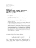
5.1. Simulation Scenarios. In order to investigate the effect of
node density and spatial distribution of the network nodes
we set up Cases A and B described below.
Case A. Irregular topology and increasing density. Network
nodes were placed at random over a circular simulation area
of radius R. Parameter R corresponds to the transmission
range of the nodes and it was set to 50 m. The sink node (ID
0) was located in the center (see Figure 2), and the number
of nodes was varied from 3 to 21.
Case B. Grid topology and increasing density. In this case the
nodes were placed at random in the different intersections of
a grid pattern. Although it is generally assumed that sensor
nodes will most likely be deployed at random, we used this
scenario in order to compare with Case A and determine
the effect of having equidistant nodes on the association
procedure. We used the same assumptions and parameter
values as in Case A (see also Figure 2).
With scenarios C and D, described below, we studied how
the algorithm scales when it is used in networks that span
across large geographical areas.
Case C. Irregular topology and increasing area. The area
covered by the network was assumed to be circular with the
sink node located in its center. All nodes were assumed to
have a circular coverage area with a transmission radius of
50 m (i.e., R). We considered areas with different radius from
6 EURASIP Journal on Wireless Communications and Networking
0
10
20
30
40
50
60
70
80
90
100
13
16
11 18
2
14
7
8
18
20
9
4
6
1
14
4
20
6
1
11
9
10
13 5
12
15
0312
16
197
19
17
2
3
1710
8
5
15
0 10 20 30 40 50 60 70 80 90 100
Figure 2: Examples of the spatial node distribution for Case A
(black dots) and Case B (white dots).
R to 10R, but we maintained a constant node density. In the
largest area we used as many as 1959 nodes, and for each
simulation run, the network nodes were repositioned.
Case D. Grid topology and increasing area. We used the same
assumptions and parameter values as in Case C.
For each scenario and a particular combination of
parameters, we ran 200 simulations in order to obtain 99%
confidence intervals for the mean network creation time.
This metric is defined as the time elapsed between the
transmission of the initial PA packet issued by the base
station until the time instant when the last node association
takes place. We also report the number of unsuccessful
attempts required by the CSMA/CA and the 2C-WSN to
transmit the signalling packets of SA-MAC. Following the
specifications of IEEE 802.15.4, in case the number of
backoffs reaches the value MaxCSMABackoffs, CSMA/CA
declares the network as unreachable.
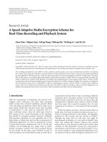
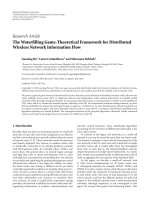
5.2. Simulation Results.
Cases A and B. In these cases all nodes are placed within the
transmission range of the base station. Figure 3 shows the
resulting mean network configuration time as a function of
the number of nodes composing the network. As seen from
the figure, 2C-WSN outperforms CSMA/CA. Furthermore,
CSMA/CA began having problems completing the network
configuration for a system consisting of as few as seven nodes.
This is due to the fact that once having reached the value
defined in the parameter MaxCSMABackoffs, CSMA/CA
givesupandreportsanetworkfailuretoupperlayers.In
this case, such layers have to decide which action will be
applied. This result clearly shows how sensitive CSMA/CA
is with respect to its parameter values. In case of the system
configuration making use of 2C-WSN, the figure shows that
0
0.2
0.4
0.6
0.8
1
Time (s)
468101214161820
Number of nodes
Irregular topology (Case A) SA-MAC+CSMA/CA
Grid topology (Case B) SA-MAC+CSMA/CA
Irregular topology (Case A) SA-MAC+2CWSN
Grid topology (Case B) SA-MAC+2CWSN
Figure 3: Network setup times for Case A and Case B.
this protocol is able to perform the network configuration
with a reasonable increase in the required time as the number
of nodes increases. These results also show that our proposal
can, in fact, guarantee the network configuration.
In order to observe the time that CSMA/CA would take
in order to configure dense networks without being restricted
by the value of MaxCSMABackoffs, we proceeded as follows.
In order to prevent CSMA/CA from giving up a network
configuration when the value of MaxCSMABackoffswas
reached, after a failed transmission attempt the correspond-
ing packet was rescheduled for transmission as many times
as necessary until its successful transmission was achieved.
We used the scenarios described in Case A and Case B, and
Ta bl e 2 summarizes the corresponding results in terms of the
number of collisions and its related effects.
Ta bl e 2 summarizes some relevant collision-related mea-
surements, on average, for both algorithms. The column
labelled Backoff limit reached indicates the average number
of times that a network failure was reported by CSMA/CA to
upper layers before a successful association was completed.
In these cases the corresponding packets had to be reinserted.
The table shows that, with as few as seven nodes, CSMA/CA
incurs in network access problems, as previously pointed
out. The column Collis. indicates the average number of
times that network nodes using CSMA/CA collided before
the network configuration was achieved. As seen in the table,
it is clear that the number of collisions is significantly higher
for CSMA/CA than for 2C-WSN. Furthermore, the number
of collisions grew with the number of nodes composing the
network, but the grow rate is lower for 2C-WSN.
CasesCandD. These cases are intended to test the scalability
of 2C-WSN with different network sizes. As previously
described, we increased the radius of the simulation area
from R to 10R in steps of R
= 50 m and maintained the same
node density.
EURASIP Journal on Wireless Communications and Networking 7
Table 2: Collision-related results.
Case A Case B
CSMA/CA 2C-WSN CSMA/CA 2C-WSN
Netw. size Backoff limit reached Collis. DSC collisions Backoff limit reached Collis. DSC collisions
3 0 1.25 1.25 0 1 1.5
4 0 3.375 1.875 0 2.375 4.375
5 0 13.5 3.625 0 4.25 5.5
6 0 17.625 15.875 0 8.875 9.375
7 0.375 28.75 13.875 0.25 9.875 10.875
8 0.375 39.625 17.5 0.25 17.625 19
9 0.125 61.5 21.375 0.25 15.875 19.875
10 1.125 94.25 39.75 1.375 39.875 27.375
11 2.75 107.75 42.875 1.875 47.125 27.25
12 2 110.75 51.125 2.75 75.5 39.5
13 3.625 128.25 54.5 2 103.5 46.75
14 3.625 161.875 58.375 5.125 142.25 50.5
15 4.375 150.625 63.75 8.125 137.625 62.25
16 6.75 214.75 69.25 6.875 178.125 66.25
17 9.5 264.5 98.375 7.5 210.625 66
18 12.375 265.75 99.75 11.625 384.5 80.5
19 10.75 304.5 114.125 15.625 274.25 111.625
20 25.125 494.625 115.125 14.125 304 107.25
21 23 502.125 114.875 19.375 533.625 136.625
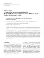
Figure 4 shows the behaviour of the creation time as
a function of the network size. Once the network includes
the nodes that are far away from the base station, the
required time for the network creation increases, but the
growth rate is rather slow. For instance, based on the data
shown in Figure 4 when the network radius increases from
R to 6R, the creation time for a random topology increases
from approximately 0.6 s to 1.5 s (Δ
= 150%) when the
corresponding area increases from 7,854 m
2
to 282,743 m
2
(Δ = 3,500%) and the number of nodes increases from
21 to 709 (Δ
= 3,276%). This relatively small increase in
configuration time is due to the limited transmission range
of the network nodes combined with a large network size
and the fact that the network configuration functions are not
centralized. This situation allows the simultaneous creation
of two or more branches of the tree in different parts of
the network. This result shows that it is feasible to use 2C-
WSN in the configuration phase of large TDMA networks in
reasonable time.
We also collected statistics regarding the tree depth in the
last hop of the network. Figure 5 shows the corresponding
results and depicts the relation between network size and
hop count. For instance, for a network radius of 6R, the
average hop count was between 7 and 8. However, under the
best circumstances in this case a node near the border of the
nework should be reached with, at the most, a 6-hop route. A
number of factors influence this result such as node density
and whether the placement of the nodes is regular or not. As
it can be seen in the figure the grid topology achieves a slighly
shorter hop count than the irregular one.
0
0.5
1
1.5
2
2.5
3
3.5
Time (s)
0 500 1000 1500 2000
Number of nodes
Irregular topology (Case C) SA-MAC+2CWSN
Grid topology (Case D) SA-MAC+2CWSN
R
2R
3R
4R
5R
6R
7R
8R
9R
10R
Network radius (R = 50 m)
Figure 4: Network configuration times for Cases C and D.
6. Experimental Platform and Evaluation
In this section, we describe a first prototype of our proposal
and provide an experimental assessment using a network
composed of four nodes. Our findings, with a small sys-
tem like this, provide a useful insight on real network
8 EURASIP Journal on Wireless Communications and Networking
0
2
4
6
8
10
12
14
Average number of hops
Irregular topology (Case C)
Grid topology (Case D)
R
2R
3R
4R
5R
6R
7R
8R
9R
10R
Network radius
Figure 5: Mean tree depth for Case C and Case D.
performance and help us foresee how such performance
would scale to larger networks.
6.1. System Configuration. The experimental platform was
developed using MicaZ motes, a commercial product
developed by Crossbow [16].Themoteincorporatesan
Atmel Atmega128L microcontroller [17] operating at 8 MHz
and comprising a 128 Kbytes program flash memory and
4 Kbytes of user memory (RAM). The mote also includes a
Chipcon CC2420 [18] IEEE 802.15.4 radio system equipped
with a 2.4 GHz RF transceiver designed for low-power
wireless applications with an effective data rate of 250 kbps.
ThemotesoperateunderTinyOS[19], a popular operat-
ing system for wireless sensor networks. TinyOS features
a component-based architecture, that is, the software is
structured in modular pieces called components. TinyOS
provides a component library including network protocols,
services, and sensor drivers. Its network architecture provides
a medium access control layer based on the CSMA/CA
protocol [20]. We developed our proposed protocol using
NesC and evaluated its performance against the CSMA/CA
component provided by TinyOS. The packet lengths were
fixed as follows: DSC 9 bytes, DLY 12 bytes, ACK
S
12 bytes,
and ACK
F
12 bytes. In our experiments we monitored the
current demanded by the sensor node which is an indication
of the instantaneous power consumption and node activity.
The curves shown in this section were obtained by using
an instrumentation setup that made use of a four-channel
digitizing oscilloscope with a 10 MHz sampling rate.
6.2. Experimental Evaluation. Our first experiments had as
main objective to determine the time required to complete a
father-and-child association, AAO. Recall that this operation
consists of exchanging four packets: DSC, DLY, ACK
S
,and
ACK
F
. Several trials were conducted placing the nodes
at a distance ranging from 1 to 20 meters in a line-of-
sight situation. The AAO time obtained throughout our
20
25
30
20
25
30
I (mA)
DSC ACK
s
DLY ACK
F
0.572 0.574 0.576 0.578 0.58 0.582 0.584
Time (s)
Father node
Child node
Figure 6: AAO in real implementation using 2C-WSN.
trials ranged between 8.09 ms and 8.33 ms. Figure 6 shows
a snapshot of an exchange of packets with the nodes placed
three meters away from each other. The solid and dotted
lines correspond to the base station (coordinator) and the
child node, respectively. The total time required to complete
the association depicted in the figure was 8.10 ms, measured
from the time the node issued the DSC packet till it
completely received the acknowledgement from the base
station, AC K
F
. The consumption for both nodes is also
shown in the figure.
The values obtained experimentally for the AAO that
resulted substantially were higher than the ones considered
in our simulations. This was mainly due to the fact that the
model of the radio chip CC2420 implemented in OMNeT++
does not take into account the switching time from the RX to
TX modes nor the data buffer or radio crystal startup delays.
As already mentioned, TinyOS uses by default the
CSMA/CA medium access protocol. For comparison pur-
poses, we carried out a second experiment for assessing the
AAO time when using CSMA/CA. Figure 7 shows a snapshot
of the packet exchanges. The time required to complete the
AAO was about 35.5 ms, that is, over four times longer than
the time required by our protocol. It is worth mentioning
that the CSMA/CA implementation makes use of the Clear
Channel Assessment (CCA) mechanism to verify that the
channel is free, after a random delay chosen in the interval
[0, 2
BE
−1].
We configured the network shown in Figure 1, with the
difference that Node 2 was moved into the communication
range of BS. Figure 8 shows a snapshot of the operation of
the network. The crosses over the traces indicate the points
at which the DSC packets collided. The first collision involves
all three nodes. In a second attempt, Node 1 issues its request
and it is able to complete its association (the check mark over
the trace indicates this fact). Nodes 2 and 3 having refrained
from attempting to issue their request, then attempt once
again. A collision results and in a second attempt, Node 2
EURASIP Journal on Wireless Communications and Networking 9
20
25
30
20
25
30
I (mA)
DSC ACK
s
DLY ACK
F
0.01 0.02 0.03 0.04 0.05 0.06 0.07 0.08 0.09
Time (s)
Father node
Child node
Figure 7: AAO in real implementation over CSMA/CA.
BS node
Node 1
Node 2
Node 3
0.09 0.10.11 0.12 0.13 0.14 0.15
Time (s)
××
××
×
Figure 8: AAO using three nodes and a coordinator over 2C-WSN.
is able to perform its association, finally Node 3 gets to join
the network, achieving the setup time in about 35 ms.
Figure 9 shows the association time obtained for the
network used in the previous case using CSMA/CA as
underlying MAC protocol. The successful completion of the
association event is marked with a check mark. As seen from
the figure, the time required for the whole operation takes
about 150 ms, which is substantially longer than the time
required by our proposal. The results are scalable to multihop
networks since the collision resolution algorithm equally
works in new areas of the network. That is, no collisions
arise among superframes that belong to different network
coordinators. Regarding this last statement, superframes are
required to use either different time slots or frequencies.
However, this superframe schedule is out of the scope of this
work.
7. Conclusions and Future Work
In this work we focused our attention on the setup phase
of TDMA wireless sensor networks. This phase is often
overlooked, but we have pointed out the various conflicts
BS node
Node 1
Node 2
Node 3
0.10.12 0.14 0.16 0.18 0.20.22 0.24 0.26
Time (s)
Figure 9: AAO using three nodes and a coordinator over
CSMA/CA.
that may arise during it. Based on the particularities of
WSNs, we proposed 2C-WSN, a conflict resolution protocol
intended to be used during the network configuration.
Our proposal is based on the advantageous properties of
the 2C conflict resolution algorithm, namely, simplicity
and fairness. We took the configuration phase of SA-
MAC (a TDMA-based synchronous MAC protocol) as a
case study and carried out a performance evaluation by
means of computer simulations and measurements in a
real system. Our first set of simulation results showed that
our proposal is able to set up a highly populated wireless
sensor network within reasonable time bounds. From the
second simulation campaign we showed that our proposal
scales well by keeping within reasonable bounds the time
required to configure networks consisting of a large number
of nodes spread over a wide geographical area. Based on these
results we showed that our proposal is robust and scalable.
We also implemented 2C-WSN in real sensor nodes and
confirmed the improvement in performance in comparison
with the widely used CSMA/CA protocol. As compared with
CSMA/CA our proposal is easier to implement, faster and the
channel access is guaranteed.
There are a number of directions in which we plan to
extend our work. In particular, we plan to conduct a series
of experiments in a real-world application such as vineyard
monitoring [21].
Acknowledgments
This work was supported by the Spanish MEC and MICINN
as well as European Commission FEDER funds, under
Grants CSD2006-00046 and TIN2009-14475-C04 and the
Regional Council of Science and Education of Castilla
La Mancha, PBI08-0228-9935 and PBI08-0273-7562. Addi-
tional funding came from
´
Area de Investigaci
´
on en Redes y
Telecomunicaciones (UAM-Iztapalapa).
References
[1] C. Buratti, A. Conti, D. Dardari, and R. Verdone, “An overview
on wireless sensor networks technology and evolution,”
Sensors, vol. 9, no. 9, pp. 6869–6896, 2009.
10 EURASIP Journal on Wireless Communications and Networking
[2] A. Bachir, M. Dohler, T. Watteyne, and K. Leung, “MAC
essentials for wireless sensor networks,” IEEE Communications
Surveys and Tutorials, vol. 12, no. 2, pp. 222–248, 2010.
[3] M. Paterakis and P. Papantoni-Kazakos, “Simple window
random access algorithm with advantageous properties,” IEEE
Transactions on Information Theory, vol. 35, no. 5, pp. 1124–
1130, 1989.
[4] F. Royo, T. Olivares, and L. Orozco-Barbosa, “A synchronous
engine for wireless sensor networks,” Telecommunication Sys-
tems, vol. 40, no. 3-4, pp. 151–159, 2009.
[5] M. Macedo, A. Grilo, and M. Nunes, “Distributed latency-
energy minimization and interference avoidance in TDMA
wireless sensor networks,” Computer Networks, vol. 53, no. 5,
pp. 569–582, 2009.
[6] D. Shu, A. K. Saha, and D. B. Johnson, “RMAC: a routing-
enhanced duty-cycle MAC protocol for wireless sensor net-
works,” in Proceedings of the 26th IEEE International Con-
ference on Computer Communications (INFOCOM ’07),pp.
1478–1486, 2007.
[7] A. Rowe, R. Mangharam, and R. Rajkumar, “RT-Link: a global
time-synchronized link protocol for sensor networks,” Ad Hoc
Networks, vol. 6, no. 8, pp. 1201–1220, 2008.
[8] K. Jamieson, H. Balakrishnan, and Y. C. Tay, “Sift: a MAC
protocolforevent-drivenwirelesssensornetworks,”inPro-
ceedings of the 3rd European Workshop on Wireless Sensor
Networks (EWSN ’06), vol. 3868 of Lecture Notes in Computer
Science, pp. 260–275, 2006.
[9] H C. Le, H. Guyennet, and N. Zerhouni, “A new contention
access method for collision avoidance in wireless sensor
networks,” in Proceedings of the 6th International Conference
on Networking (ICN ’07), p. 27, April 2007.
[10] R. Garces and J. J. Garcia-Luna-Aceves, “Floor acquisition
multiple access with collision resolution,” in Proceedings of the
2nd Annual International Conference on Mobile Computing and
Networking (MobiCom ’96), pp. 187–197, ACM, November
1996.
[11] L. Alarcon-Ramos, M. Lopez-Guerrero, and D. Makrakis,
“Adaptive 2C: a novel access control for fair and efficient
channel sharing,” in Proceedings of the Canadian Conference
on Electrical and Computer Engineering (CCECE ’07), pp. 643–
646, 2007.
[12] IEEE 802.15.4, “Part 15.4:Wireless Medium Access Control
(MAC) and Physical Layer (PHY) Specifications for Low-Rate
Wireless Personal Area Networks (WPANs),” IEEE standard
for information technology, September 2006.
[13] A. Koub
ˆ
aa, A. Cunha, M. Alves, and E. Tovar, “TDBS: a time
division beacon scheduling mechanism for ZigBee cluster-tree
wireless sensor networks,” Real-Time Systems,vol.40,no.3,
pp. 321–354, 2008.
[14] IEEE 802.15 WPAN Task Group 4b (TG4b), “Wireless
medium access control (MAC) and physical layer (PHY)
specifications for lowrate wireless personal area networks (LR-
WPANs),” IEEE standard for information technology.
[15] “Castalia: A Simulator for WSN,” ta
.com.au/.
[16] MICAz 2.4GHz, “CrossbowR wireless platform for low-power
sensor networks,” />[17] Atmel Atmega128L, “High-performance, Low-power AVR R
8-bit Microcontroller,” />[18] ChipconR CC24020, “CC2420 2.4 GHz IEEE 802.15.4/Zigbee-
ready RF Transceiver,” />[19] “TinyOS project,” />[20] J. Polastre, J. Hill, and D. Culler, “Versatile low power media
access for wireless sensor networks,” in Proceedings of the
2nd International Conference on Embedded Networked Sensor
Systems (SenSys ’04), pp. 95–107, November 2004.
[21] T. Olivares, L. Orozco-Barbosa, V. L´oopez, and P. Pedr´oon,
“Wisevine: wireless sensor networks applied to vineyards,” in
Proceedings of the ACM International Workshop on Real-World
Wireless Sensor Network, Uppsala, Sweden, June 2006.