Báo cáo hóa học: " Research Article Performance Analysis of the 3GPP-LTE Physical Control Channels" pdf
Bạn đang xem bản rút gọn của tài liệu. Xem và tải ngay bản đầy đủ của tài liệu tại đây (780.86 KB, 10 trang )
Hindawi Publishing Corporation
EURASIP Journal on Wireless Communications and Networking
Volume 2010, Article ID 914934, 10 pages
doi:10.1155/2010/914934
Research Article
Performance Analysis of the 3GPP-LTE Physical Control Channels
S. J. Thiruvengadam
1, 2
and Louay M. A. Jalloul
3
1
Smart Antenna Research Group, Department of Electrical Eng ineering, Stanford University, USA
2
TIFAC CORE in Wireless Technologies, Thiagarajar College of Engineering, Madurai 625015, India
3
Beceem Communications Inc., Santa Clara, CA 95054, USA
Correspondence should be addressed to Louay M. A. Jalloul,
Received 8 May 2010; Revised 24 September 2010; Accepted 11 November 2010
Academic Editor: Ashish Pandharipande
Copyright © 2010 S. J. Thiruvengadam and L. M. A. Jalloul. This is an open access article distributed under the Creative Commons
Attribution License, which permits unrestricted use, distribution, and reproduction in any medium, provided the original work is
properly cited.
Maximum likelihood-based (ML) receiver structures are derived for the decoding of the downlink control channels in the new
long-term evolution (LTE) standard based on multiple-input and multiple-output (MIMO) antennas and orthogonal frequency
division multiplexing (OFDM). The performance of the proposed receiver structures for the physical control format indicator
channel (PCFICH) and the physical hybrid-ARQ indicator channel (PHICH) is analyzed for various fading-channel models and
MIMO schemes including space frequency block codes (SFBC). Analytical expressions for the average probability of error are
derived for each of these physical channels. The impact of channel-estimation error on the orthogonality of t he spreading codes
applied to users in a PHICH group is investigated, and an expression for the signal-to-self interference plus noise ratio is derived
for Single Input Multiple Output (SIMO) systems. Finally, a matched filter bound on the probability of error for the PHICH in a
multipath fading channel is derived. The analytical results are validated against computer simulations.
1. Introduction
A new standard for broadband wireless communications has
emerged as an evolution to the Third Generation Part-
nership Project (3GPP) wideband code-division multiple
access (CDMA) Universal Mobile Telecommunication Sys-
tem (UMTS), termed long term evolution or LTE (3GPP-
release8).Themaindifference between LTE and its prede-
cessors is the use of scalable OFDM (orthogonal frequency
division multiplexing, used on the downlink with channel
bandwidth of 1.4 all the way up to 20 MHz.) together with
MIMO (multiple input multiple output, configurations of
up to 4 transmit antennas at the base station and 2 receive
antennas at the user equipment.) antenna technology as
shown in Table 1. Compared to the use of CDMA in releases
4–7, the LTE system separates users in both the time and
frequency domain. OFDM is bandwidth scalable, the symbol
structure is resistant to multipath delay spread w ithout
the need for equalization, and is more suitable for MIMO
transmission and reception. Depending on the antenna
configuration, modulation, coding and user category, LTE
supports both frequency-division duplexing (FDD) as well
as time-division duplexing (TDD) with peak data rates of
300 Mbps on the downlink and 75 Mbps on the uplink [1–
3]. In this paper, the FDD frame structure is analyzed, but the
results also reflect the performance of TDD frame structure.
Another fundamental dev iation in LTE specification
relative to previous standard releases is the control channel
design and structure to support the capacity enhancing fea-
turessuchaslinkadaptation,physicallayerhybridautomatic
repeat request (ARQ), and MIMO . Correct detection of the
control channel is needed before the payload information
data can be successfully decoded. Thus, the overall link
and system performance are dependent on the successful
decoding of these control channels.
The performance of the physical downlink control
channels in the typical urban (TU-3 km/h) channel was
reported in [4] using computer simulations only, without
rigorous mathematical analyses. The motivation behind this
paper is to describe the analytical aspects of the performance
of optimal receiver principles for the decoding of the LTE
physical control channels. We develop and analyze the per-
formance of ML receiver structures for the downlink physical
control format indicator channel (PCFICH) as well as the
2 EURASIP Journal on Wireless Communications and Networking
Table 1: System numerology.
Channel
bandwidth
(MHz) (W)
1.4 3.0 5.0 10.0 15.0 20.0
Number of
physical
resource
blocks (N
DL
RB
)
615255075100
FFT size (N) 128 256 512 1024 1536 1024
Sampling
frequency
(Msps) ( f
s
)
1.92 3.84 7.68 15.36 23.04 30.72
physical hybrid ARQ indicator channel (PHICH) in the
presence of additive white Gaussian noise, frequency selective
fading channel with different transmit and receive antenna
configurations, and space-frequency block codes (SFBC).
These analyses provide insight into system performance and
can be used to study sensitivity to design parameters, for
example, channel models and algorithm designs. Further,
it would serve as a reference tool for fixed-point computer
simulation models that are developed for hardware design.
Therestofthepaperisorganizedasfollows.Abrief
description of the LTE control channel specification is given
in Section 2. The BER analyses of the physical channels
PCFICH and PHICH are given in Sections 3 and 4,
respectively. Section 5 contains some concluding remarks.
Notation.
◦, ∗, and H denote element by element product,
complex conjugate, and conjugate transpose, respec tively.
x, y=
i
x
i
y
∗
i
is the inner product of the vectors x and
y.
⊗ denotes the convolution operator.
2. Brief Description of the 3GPP-LTE Standard
The downlink physical channels carry information from the
higher layers to the user equipment. The physical downlink
shared channel (PDSCH) carries the payload-information
data, physical broadcast channel (PBCH) broadcasts cell
specific information for the entire cell-coverage area, physical
multicast channel (PMCH) is for multicasting and broad-
casting information from multiple cells, physical downlink
control channel (PDCCH) carries scheduling information,
physical control format indicator channel (PCFICH) conveys
the number of OFDM symbols used for PDCCH and
physical hybrid ARQ indicator Channel (PHICH) transmits
the HARQ acknowledgment from the base station (BS). BS
in 3GPP-LTE is typically referred to as eNodeB. Downlink
control signaling occupies up to 4 OFDM symbols of the
first slot of each subframe, followed by data transmission that
starts at the next OFDM symbol as the control signaling ends.
This enables support for microsleep which provides battery-
life savings and reduced buffering and latency [4]. Reference
signals transmitted by the BS are used by UE for channel
estimation, timing and frequency synchronization, and cell
identification.
Table 2: Power delay profiles for pedestrian B and ITU channel
models.
Ped-B channel model TU channel model
Delay (nsec)Average power (dB) Delay (μsec) Average power (dB)
0 0 0 1.000
200
−0.9 0.813 0.669
800
−4.9 1.626 0.448
1200
−8.0 2.439 0.300
2300
−7.8 3.252 0.200
3700
−23.9 4.056 0.134
The downlink OFDM FDD radio frame of 10 ms
duration is equal ly divided into 10 subframes where each
subframe consists of two 0.5 ms slots. Each slot has 7 or
6 OFDM symbols depending on the cyclic prefix (CP)
duration. Two CP durations are supported: normal and
extended. The entire time-frequency grid is divided into
physical resource blocks (PRB), wherein each PRB contains
12 resource elements (subcarriers). PRBs are used to describe
the mapping of physical channels to resource elements.
Resource element groups (REG) are used for defining the
control channels to resource element mapping. The size of
the REG varies depending on the OFDM symbol number and
antenna configuration [1]. The PCFICH is always mapped
into the first OFDM symbol of the first slot of each subframe.
For the normal CP duration, the PHICH is also mapped into
the first OFDM symbol of the first slot of each subframe. On
the other hand, for the extended CP duration, the PHICH
is mapped to the first 3 OFDM symbols of the first slot of
each subframe. All control channels are organized as symbol-
quadruplets before being mapped to a single REG. In the first
OFDM symbol, two REGs per PRB are available. In the third
OFDM, there are 3 REGs per PRB. In the second OFDM
symbol, the number of REGs available per PRB will be 2
for single- or two-transmit antennas, and 3 for four-transmit
antennas.
This paper focuses on the performance analyses of the
PCFICH and PHICH between the UE and the BS in three
types of channels: (1) static (additive white Gaussian noise
(AWGN)), (2) frequency flat-fading, and (3) ITU frequency
selective channel models. The power-delay profiles of the
ITU models, used in the analyses, are given in Ta bl e 2.
3. Physical Control Format Indicator Channel
ThetwoCFIbitsareencodedusinga(32,2)blockcodeas
shown in Ta bl e 3. The 32 encoded bits are QPSK modulated,
layer mapped, and, finally, are resource element mapped.
3.1. PCFICH with SIMO Processing. The received signal
is processed as follows: the cyclic prefix is removed, then
the FFT is taken, followed by resource-element demapping.
The complex-valued output at the k-th receive antenna is
modeled as
y
k
= h
k
◦ d
(n)
+ u
k
, k = 1, 2, K,(1)
EURASIP Journal on Wireless Communications and Networking 3
Table 3: CFI (32,2) Block code [2].
CFI b
0
,b
1
, ,b
31
1 0, 1, 1, 0, 1, 1, 0, 1, 1, 0, 1, 1, 0, 1,1,0,1,1,0,1, 1, 0, 1, 1, 0, 1, 1, 0, 1, 1, 0, 1
2 1, 0, 1, 1, 0, 1, 1, 0, 1, 1, 0, 1, 1, 0,1,1,0,1,1,0, 1, 1, 0, 1, 1, 0, 1, 1, 0, 1, 1, 0
3 1, 1, 0, 1, 1, 0, 1, 1, 0, 1, 1, 0, 1, 1,0,1,1,0,1,1, 0, 1, 1, 0, 1, 1, 0, 1, 1, 0, 1, 1
4(Reserved) 0, 0, 0, 0, 0, 0, 0, 0, 0, 0, 0, 0, 0, 0,0,0,0,0,0,0, 0, 0, 0, 0, 0, 0, 0, 0, 0, 0, 0, 0
where K is the number of receive antennas at UE, y
k
is 16×1
received subcarrier vector, d
(n)
is the 16 × 1 complex QPSK
symbol vector corresponding to the 32-bit CFI codewords,
1
≤ n ≤ 3, h
k
is 16 ×1 complex channel frequency response,
and u
k
represents the contribution of thermal noise and
interference, modeled as zero-mean circularly symmetr ic
complex Gaussian with covariance E[u
k
u
H
k
] = σ
2
u
I. Modeling
the interference as Gaussian is justified, since in a multicell
multisector system such as LTE, there are typically between 3
to 6 dominant interferers. These interferers are uncorrelated
due to independent large-scale propagation, short-term
fading, and uncorrelated scrambling sequences. Therefore,
their sum can be well approximated as a Gaussian random
variable. Conditioned on h
k
, y
k
is a complex Gaussian
random variable. Maximizing the log-likelihood function of
y
k
given h
k
, results in the following ML decision rule:
CFI
= min
m=1,2,3
K
k=1
y
k
−
h
k
◦ d
(m)
2
,(2)
which simplifies to
CFI
= arg max
m=1,2,3
z
(m)
,(3)
where the soft outputs are given by
z
(m)
=
K
k=1
z
(m)
k
for m = 1, 2, 3, (4)
where z
(m)
k
= Re{y
k
◦ h
∗
k
, d
(m)
} for m = 1, 2, 3. Expanding
(4) yields
z
(m)
=
K
k=1
Re
⎧
⎨
⎩
16
i=1
h
i,k
2
c
(
1, m
)
+ u
i,k
d
(m)
∗
i
h
∗
i,k
⎫
⎬
⎭
,
m
= 1, 2,3,
(5)
where c(n, m)
=
16
i=1
d
(n)
i
d
(m)
∗
i
. Without loss of generality, it
is assumed that the first CFI codeword is used, that is n
= 1,
thus we have
c
(
1, m
)
=
16
i=1
d
(1)
i
d
(m)
∗
i
=
⎧
⎪
⎪
⎪
⎪
⎨
⎪
⎪
⎪
⎪
⎩
16 if m = 1
−6 − j10 if m = 2
−5+j11 if m = 3
(6)
as per the predefined CFI codewords in [1]. Then, the
probability of error is well approximated by the union bound
as
P
(CFI)
b
≤
3
m=2
P
z
(1)
<z
(m)
| n = 1
=
3
m=2
P
z
(1)
− z
(m)
< 0 | n = 1
,
(7)
where P(z
(1)
− z
(m)
< 0 | n = 1) is the pair-wise error
probability (PEP). In the case of a static AWGN channel with
h
i,k
= h, ∀i, k, and single-receive antenna, let x = z
(1)
1
− z
(2)
1
and y = z
(1)
1
−z
(3)
1
.Thus,x is Gaussian w ith mean 22|h|
2
and
variance 22σ
2
u
|h|
2
and y is Gaussian with mean 21|h|
2
and
variance 21σ
2
u
|h|
2
. Thus, the union bound can be evaluated
to be
P
(CFI)
b
≤
1
2
erfc
⎛
⎜
⎝
11|h|
2
σ
2
u
⎞
⎟
⎠
+
1
2
erfc
⎛
⎜
⎝
10.5|h|
2
σ
2
u
⎞
⎟
⎠
. (8)
The union bound can b e tightened further, by improving the
evaluation of the PEP using the joint probability of error due
to CFI
= 2 and CFI = 3. Then, the union bound becomes
P
(CFI)
b
≤
1
2
erfc
⎛
⎜
⎝
11|h|
2
σ
2
u
⎞
⎟
⎠
+
1
2
erfc
⎛
⎜
⎝
10.5|h|
2
σ
2
u
⎞
⎟
⎠
−
1
4
erfc
⎛
⎜
⎝
11|h|
2
σ
2
u
⎞
⎟
⎠
erfc
⎛
⎜
⎝
10.5|h|
2
σ
2
u
⎞
⎟
⎠
.
(9)
Using the bound that erfc(x)
≤ exp(−x
2
), the joint
probability term can be written as,
1
4
erfc
⎛
⎜
⎝
11|h|
2
σ
2
u
⎞
⎟
⎠
erfc
⎛
⎜
⎝
10.5|h|
2
σ
2
u
⎞
⎟
⎠
≤
1
4
exp
−
21.5|h|
2
σ
2
u
.
(10)
For fl at-fading channels, the average pair-wise probability of
error, averaged over the channel
|h|
2
distribution, is given by
P
(CFI)
b
= E
|h|
2
P
(CFI)
b
. (11)
4 EURASIP Journal on Wireless Communications and Networking
For a Rayleigh fading channel, (11)reducesto[5]
P
(CFI)
b,flat
≤
2
i=1
1 − μ
i
2
K
K−1
k=0
⎛
⎝
K − 1+k
k
⎞
⎠
1+μ
i
2
k
− P
CFI
b3,flat
,
(12)
where P
CFI
b3,flat
is evaluated to be
P
CFI
b3,flat
=
1
2
2K+1
(
K
− 1
)
!
1+γ
K
K
−1
k=0
b
k
(
K
− 1+k
)
!
γ
1+γ
k
,
(13)
where b
k
=
K−1−k
n=0
2K−1
n
, γ = 21.5γ, μ
i
=
s
i
γ/(1 + s
i
γ),
and γ
= 1/σ
2
u
is the SNR per tone per antenna and the scaling
factors s
1
= 11 and s
2
= 10.5.
3.2. Analysis of CFI with Repetition Coding. In this section,
we compare the performance of the (32,2) block code of
Table 3 used for CFI encoding with a simple rate 1/16
repetition code. The repetition code for CFI
= 1is
represented by a 32-bit-length vector [0 1
···01],CFI= 2
by [1 0
··· 10], and CFI = 3by[11··· 11].When
CFI
= 1orCFI= 2, the Hamming distance between the
other codewords are 32 and 16, otherwise, the Hamming
distance is 16. Since the CFI assumes the value between 1 and
3, in an equiprobable manner, the probability of error, in the
static AWGN channel, is given by
P
(CFI)
b,repetition
≤
1
3
erfc
⎛
⎜
⎝
16|h|
2
σ
2
u
⎞
⎟
⎠
+
2
3
erfc
⎛
⎜
⎝
8|h|
2
σ
2
u
⎞
⎟
⎠
. (14)
The expression in (14) is compared to that in (9).
3.3. PCFICH with Transmit Diversit y Processing. Tra ns mi t
diversity with two-transmit antennas or four-transmit anten-
nas, is achieved using space frequency block code (SFBC) in
combination with layer mapping [1]. Assume that there are
two transmit antennas at the BS transmitter and K receive
antennas at the UE. The received signal is processed as
follows. The output at the lth layer (two consecutive tones),
is given by
y
l,k
= H
l,k
d
(n)
l
+ u
l,k
0 ≤ l ≤ M
layer
symb
− 1, 1 ≤ k ≤ K,
(15)
where M
layer
symb
= M
symb
/2 = 8, y
l,k
is a 2 × 1 received-signal
vector at the kth receive antenna for the lth layer, d
(n)
l
is 2 ×1
transmit signal vector corresponds to n, where 1
≤ n ≤ 3, at
the lth layer, and u
l,k
denotes 2 ×1 thermal-noise vector. The
channel matrix H
l,k
is given by
H
l,k
=
1
√
2
⎡
⎣
h
(l)
k,1
−h
(l)
k,2
h
(l)
∗
k,2
h
(l)
∗
k,1
⎤
⎦
, (16)
h
(l)
k,m
is the complex channel frequency response between mth
transmit antenna and kth receive antenna, at lth symbol
layer. The maximal r a tio combiner (MRC) output is given
as
z
l,k
= H
H
l,k
y
l,k
0 ≤ l ≤ M
layer
symb
− 1, 1 ≤ k ≤ K. (17)
The decision on the CFI is taken as in (3), and the soft output
variable z
(m)
is given by
z
(m)
=
K
k=1
z
(m)
k
for m = 1, 2, 3, (18)
where z
(m)
k
= Re{y
k
◦ h
∗
k
, d
(m)
}, m = 1, 2, 3.
For flat-fading channel, H
l,k
= H
k
= (1/
√
2)
h
k,1
−h
k,2
h
∗
k,2
h
∗
k,1
.
Then (18)becomes,
z
(m)
=
K
k=1
Re
⎛
⎜
⎜
⎝
M
layer
symb
−1
l=0
H
H
k
H
k
c
(
1, m
)
+
M
layer
symb
−1
l=0
H
H
k
u
l,k
, d
(m)
l
⎞
⎟
⎟
⎠
for m = 1, 2, 3.
(19)
Without loss of generality, it is assumed that the first CFI
codeword is used, that is n
= 1, where
c
(
1, m
)
=
M
layer
symb
−1
l=0
d
(1)
l
, d
(m)
l
=
⎧
⎪
⎪
⎪
⎪
⎨
⎪
⎪
⎪
⎪
⎩
16 if m = 1
−6 − j10 if m = 2
−5+j11 if m = 3
.
(20)
Substituting for H
k
in (19), it becomes
z
(m)
=
K
k=1
⎛
⎜
⎜
⎝
Re{c
(
1, m
)
}
2
h
k,1
2
+
h
k,2
2
+Re
⎧
⎪
⎪
⎨
⎪
⎪
⎩
M
layer
symb
−1
l=0
H
H
k
u
l,k
, d
(m)
l
⎫
⎪
⎪
⎬
⎪
⎪
⎭
⎞
⎟
⎟
⎠
, m = 1, 2, 3.
(21)
Conditioned on H
k
, z
(m)
is Gaussian with mean
K
k
=1
(Re{c(1, m)}/2)(|h
k,1
|
2
+ |h
k,2
|
2
)andvariance
4σ
2
u
K
k
=1
(|h
k,1
|
2
+ |h
k,2
|
2
). The probability of error is
well approximated by the union bound, as shown in (10).
In the case of single-receive antenna, let x
= z
(2)
1
−z
(1)
1
and
y
= z
(3)
1
− z
(1)
1
. x is Gaussian with mean 11(|h
k,1
|
2
+ |h
k,2
|
2
)
and variance 11σ
2
u
(|h
k,1
|
2
+ |h
k,2
|
2
)andy is Gaussian with
mean 10.5(
|h
k,1
|
2
+ |h
k,2
|
2
)andvariance10.5σ
2
u
(|h
k,1
|
2
+
|h
k,2
|
2
). In the static AWGN channel, conditioned on |h|, the
EURASIP Journal on Wireless Communications and Networking 5
union bound is evaluated to be
P
(CFI)
b
≤
1
2
erfc
⎛
⎜
⎝
11|h|
2
σ
2
u
⎞
⎟
⎠
+
1
2
erfc
⎛
⎜
⎝
10.5|h|
2
σ
2
u
⎞
⎟
⎠
−
1
4
erfc
⎛
⎜
⎝
11|h|
2
σ
2
u
⎞
⎟
⎠
erfc
⎛
⎜
⎝
10.5|h|
2
σ
2
u
⎞
⎟
⎠
.
(22)
For the MISO flat-fading channel, the average probability of
error, averaged over the channel
|h|
2
distribution, is given by
(13)withμ
i
=
0.5s
i
γ/(1 + 0.5s
i
γ). For MIMO (2 × 2) flat-
fading channel, the diversity order L
= 4 and the average
probability of error is given by
P
(CFI)
b
≤
2
i=1
1 − μ
i
2
L
L−1
k=0
⎛
⎝
L − 1+k
k
⎞
⎠
1+μ
i
2
k
− P
CFI
b3,flat
,
(23)
where
P
CFI
b3,flat
=
1
2
2L+1
(
L
− 1
)
!
1+γ
L
L
−1
k=0
b
k
(
L
− 1+k
)
!
γ
1+γ
k
,
(24)
where b
k
=
L−1−k
n
=0
2L−1
n
.
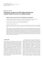
The PCFICH performance in the presence of AWGN is
shown in Figure 1. It is seen that the Union Bound approx-
imation closely matches with the Monte Carlo simulation
results. It is observed that the predefined codes for CFI
yields approximately 0.5 dB SNR improvement compared to
a repetition code, at the block-error rate (BLER) of 10
−2
.
Currently, the fourth CFI codeword in Ta bl e 3 is reserved
for future expansion. When all the four codewords are used
to convey the CFI, an additional term is introduced in the
error probability given as (1/2) erfc(
10.5|h|
2
/σ
2
u
) and the
Union Bound becomes
P
(CFI)
b
≤
1
2
erfc
⎛
⎜
⎝
11|h|
2
σ
2
u
⎞
⎟
⎠
+erfc
⎛
⎜
⎝
10.5|h|
2
σ
2
u
⎞
⎟
⎠
. (25)
Thus, it requires an additional 0.45 dB (approximately) to
achieve the BLER of 10
−2
, compared to using the first three
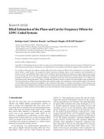
codewords. The PCFICH performance in the presence of
Rayleigh fading channels is shown in Figure 2.
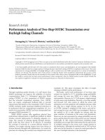
4. Physical Hybrid ARQ Indicator Channel
The PHICH carries physical hybrid ARQ ACK/NAK indica-
tor (HI). Data arrives to the coding unit in form of indicators
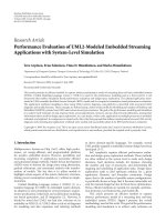
for HARQ acknowledgement. Figure 3 shows the PHICH
transport channel and physical channel processing on hybrid
ARQ data, w
n
is the spreading code for nth user in a PHICH
group, obtained from an orthogonal set of codes [1]. In LTE,
10
−3
10
−2
10
−1
10
0
SNR per-tone per-antenna (dB)
BLER
PCFICH detection in AWGN
SISO simulation
SISO UB
SISO analytical
SIMO simulation
SIMO UB
SIMO analytical
SISO Rep.code analytical
−14 −12 −10 −8 −6 −4
−2
Figure 1: PCFICH performance in AWGN.
10
−3
10
−2
10
−1
10
0
SNR per-tone per-antenna (dB)
BLER
SISO simulation
SISO analytical
MISO simulation
MISO analytical
SIMO simulation
SIMO analytical
MIMO simulation
MIMO analytical
−15
−10 −50 5 10
PCFICH: performance in flat fading channels
Figure 2: PCFICH performance in flat-fading channel.
2M spreading sequences are used in a PHICH group, where
M
= 4 for normal CP and 2 for extended CP. The first set
of M spreading sequences are formed by M
× M Hadamard
matrix, and the second set of M spreading sequences are in
quadrature to the first set.
4.1. PHICH with SIMO Processing. The received signal is
processed as follows. The cyclic prefix is removed, then the
FFT is taken, followed by resource element demapping. T he
6 EURASIP Journal on Wireless Communications and Networking
R = 1/3
repetition
coding
W
j
×4
1bit
12 sub-carriers
BPSK
Mod
Layer
mapping and
precoding
Mapping
REG
IFFT
Transport
channel
Physical
channel
Scrambling
Figure 3: PHICH transmit processing.
output that represents the ith resource-element group and
kth receiver antenna is given by
y
i,k
= h
i,k
◦
⎛
⎝
x
1
P
1
2
w
1
+
M
n=2
P
n
2
w
n
x
n
+ j
M
n=1
P
n
2
w
n
x
n
⎞
⎠
+ u
i,k
, i = 1, 2, 3.
(26)
where y
i,k
is an M × 1vector,P
n
and
P
n
, n = 1, M are
the power levels of the M orthogonal codes (for the normal
CP case), x
n
∈ (1, −1) is the data bit value of the nth user
HI, and x
n
and h
i,k
is an M × 1 complex channel frequency
response vector. Without loss of generality, it is assumed
that the desired HI channel to be decoded uses the first
orthogonalcodedenotedasw
1
. The second and third terms
in (26) denote the remaining 2M
− 1 spreading codes used
for the other HI channels within a PHICH group (in this
analytical model, we treat the general case of the normal
CP. The extended CP is easily handled as shown in the
final error-rate formulas.) The term u
i,k
denotes the thermal
noise, which is modeled as circularly symmetric zero-mean
complex Gaussian with covariance E[u
i,k
u
H
i,k
] = σ
2
u
I.
The ML decoding is given by
z
=
K
k=1
z
k
, (27)
where K is the number of antennas at the UE receiver and
z
k
=
3
i=1
z
i,k
, (28)
where
z
i,k
= Re
y
i,k
◦
h
∗
i,k
, w
1
, (29)
where the estimated channel frequency response
h
i,k
is given
by
h
i,k
= h
i,k
+ e
i,k
, e
i,k
is the estimation error which is
uncorrelated with h
i,k
and zero-mean complex Gaussian with
covariance σ
2
e
I. By expanding (29), we get that
z
i,k
= Re
⎛
⎝
h
i,k
◦
h
∗
i,k
◦ w
1
, w
1
x
1
P
1
2
+
M
n=2
h
i,k
◦
h
∗
i,k
◦ w
n
, w
1
P
n
2
x
n
+ j
M
n=1
h
i,k
◦
h
∗
i,k
◦ w
n
, w
1
P
n
2
x
n
+
u
i,k
◦
h
∗
i,k
, w
1
⎞
⎠
.
(30)
Note that
w
i
, w
j
=
M, i=j
0, i
/
= j
.Thus(28)becomes
z
k
=
3
i=1
M
m=1
h
(m)
i,k
2
P
1
2
x
1
+Re
⎛
⎝
3
i=1
M
m=1
h
(m)
i,k
e
(m)
∗
i,k
⎞
⎠
P
1
2
x
1
− Im
⎛
⎝
3
i=1
M
m=1
h
(m)
i,k
e
(m)
∗
i,k
⎞
⎠
P
1
2
x
1
+Re
⎛
⎝
3
i=1
M
m=1
h
(m)
∗
i,k
u
(m)
i,k
⎞
⎠
+Re
⎛
⎝
3
i=1
M
m=1
e
(m)
∗
i,k
u
(m)
i,k
⎞
⎠
,
(31)
For ideal channel estimation, then due to the orthogonality
property of the spreading codes, no interference is intro-
duced to w
1
from the other HI channels within a PHICH
group. However, in the presence of channel-estimation error,
self-interference and cochannel interference are introduced
as seen in the second and third terms, respectively, in (31).
Since
|x
1
|
2
= 1and|x
1
|
2
= 1, the signal to interference plus
noise ratio (SINR) of the decision statistic z is thus given by
γ
non-idealCE
z
=
K
k=1
P
1
3
i=1
M
m=1
h
(m)
i,k
2
2
σ
2
e
P
1
+
P
1
/2
3
i
=1
M
m
=1
h
(m)
i,k
2
+ σ
2
u
3
i
=1
M
m
=1
h
(m)
i,k
2
+3Mσ
2
u
σ
2
e
. (32)
EURASIP Journal on Wireless Communications and Networking 7
−8
−7
−6
−5
−4
−3
−2
−1
Desired-to-interference power ratio (dB)
SNRloss(dB)
σ
2
e
= 0.125
σ
2
e
= 0.25
σ
2
e
= 0.5
−10 −8 −6 −4 −20 2 4
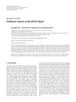
Figure 4: Effect of channel estimation error in PHICH.
In the case of a static AWGN channel with a single antenna at
the UE receiver, that is, h
(m)
i,k
= h, ∀i, m, k, the SINR is simply
given by
γ
non-idealCE
z
=
P
G
P
1
|h|
4
0.5σ
2
e
P
1
+
P
1
|
h|
2
+ σ
2
u
|h|
2
+ σ
2
u
σ
2
e
, (33)
where P
G
= 12 in (33) is the processing gain obtained from
the spreading code of length 4, and (3,1) repetition code
in the case of normal CP [1, 2]. In case of extended CP, a
maximum of 4 HI channels are allowed in a PHICH group,
and hence a spreading code of length 2 is used for each HI
channel, which results in P
G
= 6.
For ideal channel estimation, σ
2
e
= 0 and the SNR of the
decision statistic z is thus given by
γ
idealCE
z
=
P
G
P
1
|h|
2
σ
2
u
. (34)
The average loss in SNR due to channel-estimation error is
given by
L
= 1 −
γ
non-idealCE
z
γ
idealCE
z
= 1 −
1
0.5
σ
2
e
/σ
2
u
P
1
+
P
1
+1+σ
2
e
.
(35)
L is plotted in Figure 4 as a function of the ratio between
the desired power to the interfering signal power (P
1
/
P
1
), for
σ
2
e
/σ
2
u
=−3dB,σ
2
e
/σ
2
u
=−6dB,andσ
2
e
/σ
2
u
=−9dB.Figure 4
shows that if P
1
=
P
1
, that is, 0 dB, with σ
2
e
= 0.5σ
2
u
, results
in a 3 dB loss in the SNR.
The probability of error in the AWGN case with a single-
receive antenna is simply P
(HI)
b
= (1/2)P(z<0 | HI = 0) +
(1/2)P(z>0
| HI = 1) = (1/2) erfc(
P
G
γ), γ is the per tone
10
−3
10
−2
10
−1
10
0
SNR per-tone per-antenna (dB)
BER
PHICH: SISO, SIMO AWGN and flat fading
SISO AWGN analytical
SISO AWGN simulation
SIMO AWGN analytical
SIMO AWGN simulation
SISO flat analytical
SISO flat simulation
SIMO flat analytical
SIMO flat simulation
−15 −10 −50 5 10
Figure 5: PHICH performance in SISO and SIMO systems.
per antenna SNR as shown in (33)and(34). The probability
of error averaged over the channel realization is given by
P
(HI)
b
= E
β
P
(HI)
b
, (36)
where β
=
3
i=1
4
m=1
|h
(m)
i,k
|
2
.Forafrequency-flatRayleigh
fading channel, (36)reducesto[5]
P
(HI)
b
=
1 − μ
2
K
K−1
k=0
⎛
⎝
K − 1+k
k
⎞
⎠
1+μ
2
k
, (37)
where μ
=
P
G
γ/(1 + P
G
γ).
The PHICH performance for static AWGN and
frequency-flat Rayleigh fading channels is shown in Figure 5,
for ideal channel estimation.
4.2. PHICH with Transmit Diversity Processing. The received
signal is processed as follows. The cyclic prefix is removed,
then the FFT is taken, followed by resource-element demap-
ping. The output at the lth layer (consecutive two tones)
on the kth receive antenna and ith resource element group
(REG) is given by
y
(i)
l,k
= H
(i)
l,k
d
(i)
l
+ u
(i)
l,k
0 ≤ l ≤ M
layer
symb
− 1, 1 ≤ k ≤ K,
i
= 1, 2,3,
(38)
where M
layer
symb
= M
symb
/(3 × 2) = 2, y
(i)
l,k
is a 2 × 1received-
signal vector, d
(i)
l
is 2 × 1 transmit-signal vector, and u
(i)
l,k
denotes 2 × 1 thermal-noise vector, and each of its elements
is modeled as circularly symmetric zero-mean complex
Gaussian with covariance E[u
(i)
l,k
u
(i)
l,k
H
] = σ
2
u
I. The channel
8 EURASIP Journal on Wireless Communications and Networking
matrix H
(i)
l,k
is given by
H
(i)
l,k
=
1
√
2
⎡
⎣
h
(l)(i)
k,1
−h
(l)(i)
k,2
h
(l)(i)
∗
k,2
h
(l)(i)
∗
k,1
⎤
⎦
, (39)
where h
(l)(i)
k,m
is a complex channel-frequency response
between mth transmit antenna and kth receive antenna, at
lth symbol layer in ith REG. The transmit-signal vector d
(i)
is
generated by layer mapping and precoding the HI data vector
x in ith REG. The 4
× 1vectorx is given by
x
= x
1
P
1
2
w
1
+
M
n=2
P
n
2
w
n
x
n
+ j
M
n=1
P
n
2
w
n
x
n
. (40)
P
n
and
P
n
n = 1, 2, 3, 4 are the power levels of the 8 spreading
codes.Thesoftoutputfromeachlayerisgivenby
z
(i)
l,k
= H
(i)
H
l,k
y
(i)
l,k
0 ≤ l ≤ M
layer
symb
− 1, 1 ≤ k ≤ K,
i
= 1, 2,3.
(41)
The ML decision statistic, is given by
z
=
K
k=1
z
k
, (42)
where
z
k
=
3
i=1
z
(i)
k
=
3
i=1
Re
⎛
⎜
⎜
⎝
M
layer
symb
−1
l=0
z
(i)
l,k
, w
1
⎞
⎟
⎟
⎠
, (43)
and where
z
(i)
l,k
= H
(i)
H
l,k
H
(i)
l,k
d
(i)
l
+ H
(i)
H
l,k
u
(i)
l,k
0 ≤ l ≤ M
layer
symb
− 1,
1
≤ k ≤ K, i = 1, 2, 3.
(44)
In a flat-fading channel, H
(i)
l,k
= H
k
∀l, i. Then the decision
statistic z is given by,
z
=
K
k=1
3
i=1
⎛
⎜
⎜
⎝
H
H
k
H
k
M
layer
symb
−1
l=0
Re
d
(i)
l
, w
1
+
M
layer
symb
−1
l=0
Re
H
H
k
u
(i)
l,k
, w
1
⎞
⎟
⎟
⎠
.
(45)
The instantaneous SNR of z is evaluated to be
SNR
z
=
K
k=1
6P
1
h
k,1
2
+
h
k,2
2
σ
2
u
. (46)
In the case of a static AWGN channel with a single antenna
at the UE receiver, that is, h
i,k
= h, ∀i, k, the SNR is given by
SNR
z
=|h|
2
(12P
1
/σ
2
u
). The probability of error is given by,
P
(HI)
b
=
1
2
erfc
P
G
γ
. (47)
10
−3
10
−2
10
−1
10
0
SNR per-tone per-antenna (dB)
BER
PHICH: MIMO AWGN, flat fading
MISO AWGN analytical
MISO AWGN simulation
MIMO AWGN analytical
MIMO AWGN simulation
MISO flat analytical
MISO flat simulation
MIMO flat analytical
MIMO flat simulation
−14 −12 −10 −8 −6 −4 −20 2 4
Figure 6: PHICH performance in MIMO systems.
For the MISO Rayleigh flat-fading channel, the average prob-
ability of error, averaged over the channel
|h|
2
distribution,
is given by [5]
P
(HI)
b
=
⎡
⎣
1 − μ
f
2
⎤
⎦
K
K
−1
k=0
⎛
⎝
K − 1+k
k
⎞
⎠
⎡
⎣
1+μ
f
2
⎤
⎦
k
, (48)
where μ
f
=
0.5P
G
γ
k
/(1 + 0.5P
G
γ
k
)andγ
k
= P
1
/σ
2
u
, is the
SNR per antenna.
For a MIMO (2
× 2) flat-fading channel, the average
probability of error is given by
P
(HI)
b
=
⎡
⎣
1 − μ
f
2
⎤
⎦
L
L
−1
k=0
⎛
⎝
L − 1+k
k
⎞
⎠
⎡
⎣
1+μ
f
2
⎤
⎦
k
, (49)
where the diversity order L
= 4.
Figure 6 shows the PHICH performance in MIMO
systems in the presence of AWGN and Rayleigh flat-
fading channels. The analytical results match well with the
computer simulations.
4.3. Matched Filter Bound for ITU Channel Models. The
objective of this section is to analyze the performance of
the LTE downlink control channel PHICH, in general, using
matched filter bounds for various practical channel models.
The base band channel impulse response can be represented
as
h
(
t
)
= g
(
t
)
⊗
p
i=1
α
i
z
i
δ
(
t −τ
i
)
=
p
i=1
α
i
z
i
g
(
t −τ
i
)
, (50)
where α
i
and τ
i
are the amplitude and delay of the ith path
which define power delay profile (PDP), z
i
is a zero-mean,
EURASIP Journal on Wireless Communications and Networking 9
unit-variance complex Gaussian random variable, g(t)
=
sin(2πWt)/πt,andW is the system bandwidth. Let
h be a
N
× 1 complex vector that contains N
R
nonzero taps which
depends on the sampling frequency, and its corresponding
system bandwidth is as shown in Table 1. The channel
frequency response is given by,
h
(
k
)
= G
(
k
)
m∈T
α
m
z
m
e
−j(2π/N)mk
k = 0, 1, , N − 1, (51)
where T is N
R
× 1 tap-locations vector of
h at which the tap
coefficient is nonzero.
The decision statistic SNR or matched filter
bound (MFB) of PHICH is a function of β
=
K
k=1
3
i=1
4
m=1
|h
(m)
i,k
|
2
= h
e
h
H
e
,whereh
e
= [h
(1)
1,1
···h
(4)
1,1
···h
(1)
3,1
···h
(4)
3,1
h
(1)
1,2
···h
(4)
3,2
···h
(1)
1,K
···h
(4)
3,K
]. Thus, the
MFB is a function of 12K independent chi-square distributed
random variables with 2 degrees of freedom. For single-
receive antenna
β
=
12
p=1
N
R
n=1
λ
p,n
x
p,n
, (52)
where x
p,n
is independent chi-square distributed random
variable with 2 deg rees of freedom and λ
p,n
is the average
power of pth element of h
e
. Since λ
p,n
is constant with respect
to p for the given PDP, MFB can be simply written as
β
= 12
N
R
n=1
λ
n
x
n
. (53)
The characteristics function of β is given by
E
e
ivβ
=
N
R
n=1
1
1 − jvλ
n
. (54)
As λ
n
’s are distinct, the probability density function is given
by
p
β
=
N
R
n=1
k
n
e
−β/λ
n
λ
n
, (55)
where k
n
=
N
R
j=1, j
/
=i
(1/(1 − (λ
j
/λ
i
))). Then, the bit-error
probability for the matched-filter o utputs is given by P
e
(γ |
β) = (1/2) er fc(
γβ)[5]. The average probability of error,
P
e
=
∞
0
P
e
(γ | β)p(β)dβ is given by
P
e
=
N
R
n=1
k
n
2
1 −
12λ
n
γ
1+12λ
n
γ
. (56)
In case of transmit diversity using SFBC, MFB of PHICH is
the function of β
=
K
k
=1
2
m
=1
3
i
=1
M
layer
symb
l=1
|h
(l)(m)
i,k
|
2
.Fora
MIMO system, the channels are assumed to be independent
and have the same statistical behavior [7]. For single-receive
antenna, the MFB is a function of 12 independent chi-square
distributed random variables with 2 deg rees of freedom, and
it is written as β
= 12
N
R
n=1
λ
n
x
n
as in (54).
10
−3
10
−2
10
−1
10
0
SNR per-tone per-antenna (dB)
BER
PHICH: TU channel N
DL
RB
= 6
MISO simulation
MIMO simulation
MISO MFB
MISO MFB
−14 −12 −10 −8 −6 −4 −20 2
Figure 7: PHICH performance in TU channel.
SNR per-tone per-antenna (dB)
BER
PHICH: MISO Ped-B channel
MFB N
DL
RB
= 50
N
DL
RB
= 50, simulation
N
DL
RB
= 6, simulation
MFB N
DL
RB
= 6
10
−3
10
−2
10
−1
10
0
−15
−10 −50
5
Figure 8: PHICH performance in Ped-B channel.
It is observed that in TU channel, all the six paths are
resolvable for the system bandwidths specified in Table 1,and
in a Ped-B channel, only 4 paths are resolvable for N
DL
RB
= 6,
corresponds to the system bandwidth of 1.4 MHz, where
N
DL
RB
is the number of PRBs used for downlink transmission.
For N
DL
RB
= 6, the average powers of resolvable taps of
each channel coefficient are [0.1883, 0.1849, 0.1197, 0.1806,
0.1131, 0.1741] for a TU channel and [0.3298, 0.0643,
0.0673, 0.0017] for a Ped-B channel. The average powers
of resolvable taps for N
DL
RB
= 50, and in a Ped-B channel
are [0.4057, 0.3665, 0.1269, 0.0663, 0.0688, 0.0017]. The
performances of PHICH for a TU channel with N
DL
RB
= 6
10 EURASIP Journal on Wireless Communications and Networking
for MISO and MIMO systems and a Ped-B channel with
N
DL
RB
= 50 and N
DL
RB
= 6 are shown in Figures 7 and 8,
respectively. It is also observed that the performance of Ped-
B channels at N
DL
RB
= 50 has approximately 4.7 dB SNR gain
with N
DL
RB
= 6, at the BER of 10
−3
, and a TU channel has 3 dB
SNR gain.
5. Conclusion
In this paper, the performance of maximum-likelihood-
method-based receiver structures for PCFICH and PHICH
was evaluated for different types of fading channels and
antenna configurations. The effect of channel-estimation
error on the orthogonality of spreading codes used in a
PHICH group was studied. These analytical results provide
a bound on the channel-estimation-error variance and thus,
ultimately decide the channel-estimation algorithm and
parameters needed to meet such a performance bound.
References
[1] 3GPP TS 36.211, “Evolved Universal Terrestrial Radio Access
(E-UTRA); Physical Channels and Modulation (Release 8)”.
[2] 3GPP TS 36.212, “Evolved Universal Terrestrial Radio Access
(E-UTRA); Multiplexing and Channel Coding (Release 8)”.
[3] 3GPP TS 36.306, “Evolved Universal Terrestrial Radio Access
(E-UTRA); User Equipment (UE) radio access capabilities
(Release 8)”.
[4] R. Love, R. Kuchibhotla, A. Ghosh et al., “Downlink control
channel design for 3GPP LTE,” in Proceedings of IEEE Wireless
Communications and Networking Conference (WCNC ’08),pp.
813–818, Las Vegas, Nev, USA, April 2008.
[5] J. Proakis, Digital Communications, McGraw-Hill, Boston,
Mass, USA, 3rd edition, 1995.
[6] F. Ling, “Matched filter-bound for time-discrete multipath
Rayleigh fading channels,” IEEE Transactions on Communica-
tions, vol. 43, no. 2, pp. 710–713, 1995.
[7] A. F. Naguib, “On the matched filter bound of transmit diversity
techniques,” in Proceedings of the International Conference on
Communications (ICC ’01), pp. 596–603, Helsinki, Finland,
June 2000.