Advances in optical and photonic devices Part 4 doc
Bạn đang xem bản rút gọn của tài liệu. Xem và tải ngay bản đầy đủ của tài liệu tại đây (1.37 MB, 20 trang )
A Tunable Semiconductor Lased Based on Etched Slots Suitable for Monolithic Integration
51
Relatively large power variations can be seen mainly because the front mirror current has
been changed significantly in the scan in order to fully explore the tuning characteristics of
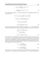
the laser. Fig. 13 shows a diagram of the wavelength peaks and their corresponding SMSRs.
A discrete tuning behaviour can be clearly seen over a tuning range of over 30 nm. With this
experimental arrangement, a total of 13 discrete wavelengths can be accessed with a
wavelength spacing around 3 nm as expected for the present design. 11 of the modes have a
SMSR larger than 30 dB, except the 1
st
and 8
th
modes whose SMSR is around 20 dB.
Fig. 13. Three section tunable laser SMSR versus wavelength for different mirror section
injection currents.
The second laser described here is similar to the one described above however no QWI is
used and therefore the wavelength is tuned around 1550 nm. Fig. 14 shows a wavelength
tuning map versus both mirror section injection currents. Discrete mode hopping occurs at
the boundaries of each different color section within this map. A total discontinuous tuning
range of more than 40 nm is observed. The SMSR map versus both mirror currents is shown
in Fig. 15. Clear islands of stable wavelength and high SMSR are observed in the maps.
Fig. 14. Wavelength tuning map versus both mirror section injection currents.
Advances in Optical and Photonic Devices
52
The threshold current is difficult to determine accurately as the device has three sections but
when both mirror section injection currents are set for a particular mode a threshold current
of 56 mA in the gain section is observed. When all three sections are biased together a
threshold current of 146 mA is observed.
Fig. 15. SMSR tuning map versus both mirror section injection currents.
For comparison a four section sample grated distributed Bragg reflector (SG-DBR) laser
wavelength map versus mirror section currents is shown in Fig. 16 below. The SG-DBR is a
state of the art semiconductor tunable laser and is used extensively in optical
communications and trace gas detection.
Fig. 16. Wavelength tuning map versus both mirror section injection currents for SG-DBR
laser diode.
A Tunable Semiconductor Lased Based on Etched Slots Suitable for Monolithic Integration
53
In order for accurate tuning to the ITU grid the super mode positions need to be fine tuned
to a particular wavelength. To do this the laser needs to be continuously tunable over some
wavelength range. The continuous tunability of one mode of the laser described above
operating around 1550 nm is shown below in Fig. 17. This mode exhibit a continuous tuning
range of 1.6 nm which allows for accurate setting of the laser to precise optical frequencies.
The continuous tuning of this mode by current injection suggests that full carrier clamping
does not take place in the mirror sections of this laser. In comparison, an SGDBR laser has a
continuous tuning range of <0.4 nm for all discrete modes which is limited by the
longitudinal mode spacing, although its quasi-continuous tuning range is much greater
(Oku, Kondo et al. 1998; Mason, Fish et al. 2000).
Fig. 17. Measured SMSR versus tuning wavelength due to a linear decrease in both mirror
currents
Fig. 18. SMSR versus wavelength for a discrete mode of the QWI laser with change in
substrate temperature from 5 to 25º C. The temperature is increased linearly from left to
right.
Advances in Optical and Photonic Devices
54
Fig. 18. shows the evolution of the wavelength and the associated SMSR due to thermal
effects associated with a change of heat sink temperature from 5 to 25 ºC, here the
temperature is varied linearly over this range increasing from left to right in Fig. 17 below.
A continuous tuning of over 2 nm while maintaining a SMSR of over 30 dB is measured. The
change in wavelength with temperature is in line with the change in the index of InP which
is 1.9x10
-4
/K.
6. Integration of an optical amplifier
In order to demonstrate the compatibility with different photonic components, a
semiconductor optical amplifier (SOA) was monolithically integrated with the tuneable laser
source. The SOA consists of an 800μm long waveguide section on the output section. The
SOA waveguide is curved to meets the output facet at a 5° angle reducing the requirement
on the antireflection coating. This method reduces the back reflections to a negligible level.
Figure 19 shows seven wavelength channels spaced 400 GHz apart which are accessible by
the device. The optical output power is significantly increased by the SOA with channel
powers ranging from 10 dBm to 14.2 dBm. All seven channels exhibit a SMSR greater than
30dB with a maximum SMSR of approximately 40dB. No deterioration of the maximum
SMSR was observed compared to the laser without the SOA. Figure 20 shows the device
output power as a function of the total laser drive current for three different SOA currents.
The gain and tuning sections of the laser were connected together for this measurement. The
device exhibits an optical output power in excess of 30 mW for a SOA current of 250 mA.
Fig. 19. Seven wavelength channels accessible by the laser integrated with an SOA showing
maximum channel power of 14.2 dBm and a maximum SMSR of approx. 40 dB
A Tunable Semiconductor Lased Based on Etched Slots Suitable for Monolithic Integration
55
Fig. 20. Optical power as a function of laser drive current for three different SOA currents.
The SOA increases the maximum device output power to 30 mW.
The graph shows how increased current injection into the amplifier increases the output
power and delays the onset of gain saturation. As the SOA is located adjacent to the mirror
section the high SOA drive currents can lead to significant heating of the reflector sections
and current leakage into the mirror section. The resulting temperature and current changes
cause a slight offset in the front reflector refractive index and a resultant change in the
reflectivity spectrum. The blue graph in Fig 20 shows how the output power can change
abruptly when the laser performs a mode jump due to thermal and current feedback from
the SOA. In a tuneable laser with control over the individual sections, these effects can be
offset by readjustment of the reflector currents.
7. Conclusion
The slotted tunable laser described here has many advantages over other state of the art
semiconductor tunable laser diodes, however there are also some disadvantages with the
slotted tunable laser design.
The key advantages of this laser are:
a. no re-growth step is required during manufacturing
b. no output facet necessary for operation so cleaving is not required
c. highly compatible with integration
d. insensitive to feed-back, therefore may not require optical isolator
e. high switching speed of the order of 1 ns
f. potentially very narrow line-width (of the order of MHz, unconfirmed)
The major advantages of the SFP tunable laser relate to the simpler manufacturing process
enabled by the lack of any re-growth step being required. In addition no cleaving is required
and this provides its compatibility with integration. This combination should provide an
opportunity to obtain high yields with complex integrated devices, such as, a tunable laser,
modulator and SOA.
Advances in Optical and Photonic Devices
56
The key disadvantages of this laser are:
a. current devices are significantly longer than competitive lasers, such as, sampled
grating distributed Bragg reflector lasers (SG-DBR).
b. current designs have a large channel spacing, of the order of 400 GHz.
The fact that the slotted lasers are longer than competitive lasers reduces the yield
advantage of the slotted tunable lasers. However, this should be proportionately less
significant in highly integrated devices that include modulators, etc.
Direct comparison with the SG-DBR laser shows that this laser is easier and cheaper to
fabricate however it cannot achieve full wavelength coverage of the C or L bands with high
SMSR as the SG-DBR can.
One of the most important considerations for a tunable laser is the ability to tune to 50 GHz
channel spacing in the C or L band for applications in DWDM applications. In order to
address this 50 GHz issue, we are now investigating ways to incorporate a phase section
that will allow more continuous tuning. The tunable laser described here also has a major
advantage over most other tunable semiconductor lasers as it can be very easily integrated
with other photonic components as describe above for integration with a SOA. More work is
needed to integrate with Mach-Zehnder modulators and other such photonic devices.
8. Acknowledgements
The authors would like to acknowledge the help received from B. Corbett, J. P.
Engelstaedter, B. Roycroft and F. Peters from Tyndall National Institute, Cork, Ireland.
The authors would like to acknowledge the funding received Science Foundation Ireland
during the course of this work.
9. References
Buus, J., M C. Amann, et al., Eds. (2005). Tunable Laser Diodes and Related Optical Sources,
Wiley-IEEE Press.
Coldren, L. and T. Koch (1984). "Analysis and design of coupled-cavity lasers Part I:
Threshold gain analysis and design guidelines." Quantum Electronics, IEEE Journal
of 20(6): 659-670.
Coldren, L. A. (2000). "Monolithic tunable diode lasers." Selected Topics in Quantum
Electronics, IEEE Journal of 6(6): 988-999.
Corbett, B. and D. McDonald (1995). "Single longitudinal mode ridge waveguide 1.3 micon
Fabry-Perot laser by modal perturbation." Electronics Letters 31(25): 2181-2182.
DeChiaro, L. F. (1991). "Spectral width reduction in multilongitudinal mode lasers by spatial
loss profiling." Lightwave Technology, Journal of 9(8): 975-986.
Engelstaedter, J. P., B. Roycroft, et al. (2008). "Laser and detector using integrated reflector
for photonic integration." Electronics Letters 44(17): 1017-1019.
Fessant, T. and Y. Boucher (1998). "Additional modal selectivity induced by a localized
defect in quarter-wave-shifted DFB lasers." Quantum Electronics, IEEE Journal of
34(4): 602-608.
Guo, W. H., L. Qiao-Yin, et al. (2004). "Fourier series expansion method for gain
measurement from amplified spontaneous emission spectra of Fabry-Perot
semiconductor lasers." Quantum Electronics, IEEE Journal of 40(2): 123-129.
A Tunable Semiconductor Lased Based on Etched Slots Suitable for Monolithic Integration
57
Healy, T., F. C. Garcia Gunning, et al. (2007). "Multi-wavelength source using low drive-
voltage amplitude modulators for optical communications." Opt. Express 15(6):
2981-2986.
Jayaraman, V., Z. M. Chuang, et al. (1993). "Theory, design, and performance of extended
tuning range semiconductor lasers with sampled gratings." Quantum Electronics,
IEEE Journal of 29(6): 1824-1834.
John, P., J. Dewi, et al. (2005). Specifying the wavelength and temperature tuning range of a
Fabry-Perot laser containing refractive index perturbations (Invited Paper), SPIE.
Klehr, A., G. Beister, et al. (2001). "Defect recognition via longitudinal mode analysis of high
power fundamental mode and broad area edge emitting laser diodes." Journal of
Applied Physics 90(1): 43.
Lambkin, P., C. Percival, et al. (2004). "Reflectivity measurements of intracavity defects in
laser diodes." Quantum Electronics, IEEE Journal of 40(1): 10-17.
Lu, Q. Y., W. H. Guo, et al. (2009). "Analysis of leaky modes in deep-ridge waveguides using
the compact 2D FDTD method." Electronics Letters 45(13): 700-701.
Mason, B., G. A. Fish, et al. (2000). Characteristics of sampled grating DBR lasers with
integrated semiconductor optical amplifiers. Optical Fiber Communication
Conference, 2000.
McDonald, D. and B. Corbett (1996). "Performance characteristics of quasi-single
longitudinal-mode Fabry-Perot lasers." Photonics Technology Letters, IEEE 8(9):
1127-1129.
O'Brien, S. and E. P. O'Reilly (2005). "Theory of improved spectral purity in index patterned
Fabry-Perot lasers." Applied Physics Letters 86(20): N.PAG.
Oku, S., S. Kondo, et al. (1998). Surface-grating Bragg reflector lasers using deeply etched
groove formed by reactive beam etching. Indium Phosphide and Related Materials,
1998 International Conference on.
Peters, F. H. and D. T. Cassidy (1991). "Model of the spectral output of gain-guided and
index-guided semiconductor diode lasers." J. Opt. Soc. Am. B 8(1): 99-105.
Phelan, R., M. Lynch, et al. (2005). "Simultaneous multispecies gas sensing by use of a
sampled grating distributed Bragg reflector and modulated grating Y laser diode."
Appl. Opt. 44(27): 5824-5831.
Phelan, R., G. Wei-Hua, et al. (2008). "A Novel Two-Section Tunable Discrete Mode Fabry-
Perot Laser Exhibiting Nanosecond Wavelength Switching." Quantum Electronics,
IEEE Journal of 44(4): 331-337.
Raring, J. W. and L. A. Coldren (2007). "40-Gb/s Widely Tunable Transceivers." Selected
Topics in Quantum Electronics, IEEE Journal of 13(1): 3-14.
Rigole, P. J., S. Nilsson, et al. (1995). "114-nm wavelength tuning range of a vertical grating
assisted codirectional coupler laser with a super structure grating distributed Bragg
reflector." Photonics Technology Letters, IEEE 7(7): 697-699.
Roycroft, B., P. Lambkin, et al. (2007). "Transition From Perturbed to Coupled-Cavity
Behavior With Asymmetric Spectral Emission in Ridge Lasers Emitting at 1.55 μm."
Photonics Technology Letters, IEEE 19(2): 58-60.
Advances in Optical and Photonic Devices
58
Ward, A. J., D. J. Robbins, et al. (2005). "Widely tunable DS-DBR laser with monolithically
integrated SOA: design and performance." Selected Topics in Quantum Electronics,
IEEE Journal of 11(1): 149-156.
Welch, D. F., F. A. Kish, et al. (2006). "The Realization of Large-Scale Photonic Integrated
Circuits and the Associated Impact on Fiber-Optic Communication Systems." J.
Lightwave Technol. 24(12): 4674-4683.
4
Monolithic Integration of Semiconductor
Waveguide Optical Isolators with Distributed
Feedback Laser Diodes
Hiromasa SHIMIZU
Tokyo University of Agriculture and Technology
Japan
1. Introduction
Monolithically InP-based photonic integrated circuits, where more than two semiconductor
optoelectronic devices are integrated in a single InP substrate, have long history of research
and development. Representatives of these InP-based photonic integrated circuits are,
electroabsorption modulator integrated distributed feedback laser diodes (DFB LDs)
(Kawamura et al., 1987, H. Soda et al., 1990) and arrayed waveguide grating (AWG)
integrated optical transmitters and receivers (Staring et al., 1996, Amersfoort et al., 1994).
Recently, dense wavelength division multiplexing (DWDM) optical transmitters and
receivers have been reported with large-scale photonic integrated circuits having more than
50 components in a single chip (Nagarajan et al., 2005).
However optical isolators have been one of the most highly desired components in photonic
integrated circuits in spite of their important roles to prevent the backward reflected light
and ensure the stable operation of LDs. Although commercially available “free space”
optical isolators are small in size and high optical isolation (>50dB) with low insertion loss
(<0.1dB) is already realized, they are composed of Faraday rotators and linear polarizers,
which are not compatible with InP based semiconductor LDs. Especially, Faraday rotators
are based on magneto-optic materials such as rare earth iron garnets, and they are quite
incompatible with InP based materials. Monolithically integrable semiconductor waveguide
optical isolators are awaited for reducing overall system size and the number of the
assembly procedure of the optical components. Also, such nonreciprocal semiconductor
waveguide devices could enable flexible design and robust operation of photonic integrated
circuits.
To overcome these challenges, we have demonstrated monolithically integrable transverse
electric (TE) and transverse magnetic (TM) mode semiconductor active waveguide optical
isolators based on the nonreciprocal loss (Shimizu & Nakano, 2004, Amemiya et al., 2006),
and reported 14.7dB/mm optical isolation at
λ
=1550nm (Shimizu & Nakano, 2006). In this
chapter, we report monolithic integration of a semiconductor active waveguide optical
isolator with distributed feedback laser diode (DFB LDs).
Advances in Optical and Photonic Devices
60
2. Fabrication of the integrated devices
The semiconductor active waveguide optical isolators in the integrated devices are based on
the nonreciprocal loss. In our TE mode semiconductor active waveguide optical isolators,
ferromagnetic metal (Fe) at one of the waveguide sidewalls provides the TE mode
nonreciprocal loss, that is, larger propagation loss for backward traveling light than forward
traveling light. The gain of the semiconductor optical amplifier (SOA) compensates the
forward propagation loss by the ferromagnetic metal (Shimizu & Nakano, 2004 & 2006).
Fig. 1 shows the cross sectional image of the TE mode semiconductor active waveguide
optical isolator taken by a scanning electron microscope. Since our waveguide optical
isolators are not based on Faraday rotation, polarizers are not necessary for optical isolator
operation. This is great advantage for monolithic integration of waveguide optical isolators
with DFB LDs. The principle of the semiconductor active waveguide optical isolators is
schematically shown in Fig. 2 (Takenaka & Nakano, 1999, Zaets & Ando, 1999). Discrete TE
mode semiconductor active waveguide optical isolators have been reported in previous
papers [Shimizu & Nakano, 2004 & 2006]. In TE mode semiconductor active waveguide
optical isolators of Fig. 1, the waveguide width (w) determines the optical isolation and
propagation loss characteristics. In narrow waveguides (w = 1.6μm), the optical confinement
factor in the Fe thin film at one of the waveguide sidewalls is 0.16%, and the optical
confinement factor of 0.16% brings the optical isolation of 14.7dB/mm (Shimizu & Nakano,
2006). Here, the optical isolation and propagation loss are almost proportional to the optical
Fig. 1. A cross sectional scanning electron microscope image of a TE mode semiconductor
active waveguide optical isolator having Fe layer at one of the waveguide sidewalls. w
denotes the waveguide stripe width.
Monolithic Integration of Semiconductor Waveguide Optical Isolators
with Distributed Feedback Laser Diodes
61
Fig. 2. Schematic operation principle of the semiconductor active waveguide optical
isolators based on the nonreciprocal loss.
confinement factor in the Fe layer. As a result, the narrow waveguides work as optical
isolators. On the other hand, in wide waveguides (w = 3μm), the optical confinement factor
in the Fe thin film at one of the waveguide sidewalls is 0.02%, the propagating light receives
small magneto-optic effect and absorption loss from the Fe layer. Hence, the wide
waveguides work as LD. Higher optical transverse modes are absorbed by the Fe layer. Fig.
3 shows light output – current characteristics of TE mode semiconductor active waveguide
optical isolators with the waveguide width w of 1.7 – 4.5 μm. TE mode semiconductor active
waveguide optical isolators of w > 2.2 μm show lasing. On the other hand, TE mode
semiconductor active waveguide optical isolators of w < 2.1 μm do not show lasing. This is
because the Fe layer at the sidewall provides propagation loss, and non-radiative surface
recombination at the etched sidewall reduces the internal quantum efficiency and gain of
the MQW active layer. The reduced internal quantum efficiency is one of the problems of TE
mode semiconductor active waveguide optical isolators. Thus, we have fabricated the
monolithically integrated devices of DFB LDs and semiconductor active waveguide optical
isolators in a simple fabrication process (Shimizu & Nakano, 2006).
The monolithically integrated devices are composed of 0.25mm-long index-coupled DFB LD
and 0.75mm-long TE mode semiconductor active waveguide optical isolator sections on
single InP chip. The DFB LD/semiconductor active waveguide optical isolator layer
structures were grown by two steps of metal-organic vapor phase epitaxy (MOVPE)
process. The active layer and grating layer were grown by the first step MOVPE. The DFB
LD and the optical isolator section have the same InGaAsP compressively strained multiple
quantum well (MQW) active layers. The MQW is composed of 14 compressively strained
(+0.7%) quantum wells and 15 tensile strained (-0.4%) InGaAsP barriers. The MQW active
layer is sandwiched by 50nm-thick InGaAsP separated confinement heterostructure (SCH)
Advances in Optical and Photonic Devices
62
Fig. 3. Light output – current charactristics of TE mode semiconductor active waveguide
optical isolators with waveguide width w of 1.7-4.5μm. Measurement temperature is 15
o
C.
layers. The photoluminescence peak wavelength of the MQW active layer was set at
1540nm. The InGaAsP index-coupled grating layer thickness is 20nm. The p-InP spacer layer
thickness between the upper InGaAsP SCH layer and the grating layer is 50nm. A grating is
defined by electron-beam lithography in DFB LD section. After the InGaAsP grating
formation by wet chemical etching, 1μm-thick p-InP upper cladding layer and p
+
InGaAs
contact layer were grown by the second step MOVPE. The deep-etched waveguides were
fabricated by Cl
2
/Ar reactive ion etching, as shown in Fig. 1. The waveguide widths were
Fig. 4. Top views of the fabricated device bar with three integrated devices of waveguide
optical isolators and DFB LDs by an optical microscope. (a) is the whole image and (b) is the
magnified image of the optical isolator / DFB LD junction. Three horizontal waveguide
stripes in (a) are corresponding to three integrated devices. The vertical line is a 5μm-width
electrode separation region. L and w denote the device length and waveguide stripe width.
The distance between the adjacent waveguide stripes is 250μm.
Monolithic Integration of Semiconductor Waveguide Optical Isolators
with Distributed Feedback Laser Diodes
63
3μm for DFB LDs and 1.6μm for waveguide optical isolators. The tapered waveguide region
where the waveguide width w gradually changes, is 10μm-long. Fig. 4 shows the top views
of the integrated devices taken by an optical microscope. The basic fabrication process
including the waveguide stripe formation, and the ferromagnetic / electrode metal
deposition, is the same as that of previous discrete TE mode semiconductor active
waveguide optical isolators (Shimizu & Nakano, 2004, 2006). The Ti/Au top electrodes and
p
+
InGaAs contact layers of the DFB LD / optical isolator sections are separated by each
other, as shown in Fig. 4(b). The electrical isolation resistance between the two top
electrodes is 1-5kΩ. It should be stressed that unlike conventional free space optical
isolators, no polarizers are needed between the DFB LD and the optical isolator section. The
device facets are as cleaved for the characterizations in this paper.
3. Characterizations
We measured the emission spectra of the integrated devices from the front and back facets
under permanent magnetic fields of +/-0.1T and 0T. The front and back facets correspond to
the optical isolator and the DFB LD sides, respectively (Fig. 4). The front facet emission is
from the DFB LD with propagating through the waveguide optical isolator. The back facet
emission is the direct emission from the DFB LD without propagating through the
waveguide optical isolator. Fig. 5 shows the emission spectra by an optical spectrum
analyzer from the (a) front and (b) back facets of the integrated devices under permanent
magnetic fields of +/-0.1T and 0T. The emitted light was coupled by lensed optical fibers.
The bias currents are 90 and 150mA for the DFB LD and active waveguide optical isolator,
respectively. The threshold current of the DFB LD is larger than 40mA. The fabricated chips
were kept at 15
o
C. The DFB LDs showed single mode emissions with
λ
= 1543.8nm. A 4dB
emission intensity change was observed for waveguide-optical-isolator-propagated DFB LD
light under magnetic field of +/-0.1T as shown in Fig. 5(a). On the other hand, such intensity
change was much smaller (0.4dB) for the back facet emission, as shown in Fig. 5(b). These
results show that the waveguide-optical-isolator- propagated DFB LD light received the
nonreciprocal loss. Therefore, this is the first demonstration of monolithic integration of the
semiconductor active waveguide optical isolators with DFB LDs. Although the output light
intensity of the waveguide optical isolator is weak (-56dBm), an anti-reflection (AR) coating
at the front facet, and a high-reflection (HR) coating at the back facet could enhance the
output intensity. Also, the optical reflection at the tapered waveguide region brings the
internal reflections along the DFB LD section, which leads to weak output intensity. By
solving these issues, the output intensity can be improved and the optical isolation can be
enhanced with the Fe layer closer to the active layer. At this stage, maximum optical
isolation is 14.7dB/mm for discrete TE mode semiconductor active waveguide optical
isolators (Shimizu & Nakano, 2006).
4. Conclusion
We have demonstrated monolithic integration of the semiconductor active waveguide
optical isolators with DFB LDs. By controlling the waveguide width of the TE mode
semiconductor active waveguide optical isolators, we established simple monolithic
Advances in Optical and Photonic Devices
64
(b)
(a)
4dB change
Fig. 5. Emission spectra of the integrated device from the (a) front and (b) back side facets
under the permanent magnetic field of +/-0.1T and 0T. Note that the three curves in (b) are
almost overlapped.
Monolithic Integration of Semiconductor Waveguide Optical Isolators
with Distributed Feedback Laser Diodes
65
integration process of the waveguide optical isolators with DFB LDs. The integrated devices
showed a single mode emission at
λ
= 1543.8nm and 4dB optical isolation. Although the
optical isolation is smaller than commercially available “free space” optical isolators at this
stage, this is the first step towards monolithically integrated isolator-DFB LD devices.
5. References
Kawamura, Y.; Wakita, K; Yoshikuni, Y; Itaya, & Asahi, H. (1987). IEEE. J. Quantum Electron.
Vol. QE-23, No. 6, (Jun. 1987) 915-918.
Soda, H.; Furutsu, M.; Sato, K.; Okazaki, N.; Yamazaki, Y.; Nishimoto, H.; & Ishikawa, H.
(1990). Electron. Lett., Vol. 26, (1990) 9-10.
Staring, A. M.; Spiekman, L. H.; Binsma, J. J. M.; Jansen, E. J.; van Dongen, T.; Thijs, P. J. A.;
Smit, M. K.; & Verbeek, B. H. (1996). IEEE. Photon. Technol. Lett., Vol. 8, No. 9, (Sep.
1996) 1139-1141.
Amersfoort, M. R.; de Boer, C. R.; Verbeek, B. H.; Demeester, P.; Looyen, A.; & van der Tol, J.
J. G. M. (1994). IEEE. Photon. Tech. Lett., Vol. 6, No. 1, (Jan. 1994) 62-64.
Nagarajan, R.; Joyner, C. H.; Schneider, R. P.; Bostak, J. S.; Butrie, T.; Dentai, A. G.; Dominic,
V. G.; Evans, P. W.; Kato, M.; Kauffman, M.; Lambert, D. J. H.; Mathis, S. K.;
Mathur, A.; Miles, R. H.; Mitchell, M. L.; Missey, M. J.; Murthy, S.; Nilsson, A. C.;
Peters, F. H.; Pennypacker, S. C.; Pleumeekers, J. L.; Salvatore, R. A.; Schlenker, R.
K.; Taylor, R. B.; Tsai, H. S.; Van Leeuwen, M. F.; Webjorn, J.; Ziari, M.; Perkins, D.;
Singh, J.; Grubb, S. G.; Reffle, M. S.; Mehuys, D. G.; Kish, F. A.; & Welch,
D. F.(2005). IEEE. J. Select. Topics Quantum. Electron. Vol. 11, No. 1, (Jan. 2005)
50-65.
Shimizu, H.; & Nakano, Y.(2004). Jpn. J. Appl. Phys. Vol. 43, (Dec. 2004) L1561-1563.
Shimizu, H.; & Nakano, Y.(2006). IEEE J. Lightwave Technol. Vol. 24, No. 1, (Jan. 2006)
38-43.
Amemiya, T.; Shimizu, H.; Nakano, Y.; Hai, P. N.; Yokoyama, M.; & Tanaka, M. (2006) Appl.
Phys. Lett. Vol. 89, (2006) 021104.
Amemiya, T.; Shimizu, H.; Yokoyama, M.; Hai, P. N; Tanaka, M; & Nakano, Y. (2007) Appl.
Opt. Vol. 46, No. 23, (Aug. 2007) 5784-5791.
Amemiya, T.; Ogawa, Y; Shimizu, H.; Munekata, H; & Nakano, Y. (2008) Appl. Phys. Expr.
Vol. 1, No. 2, (Jan. 2008) 022002.
Takenaka, M.; & Nakano. (1999), Y. Proceeding of 11
th
International Conference on Indium
Phosphide and related materials, 289.
Zaets, W.; & Ando, K. (1999) IEEE., Photon. Tech. Lett. Vol. 11, (Aug. 1999) 1012-
1014.
Vanwolleghem, M.; Van Parys, W.; Van Thourhout, D.; Baets, R.; Lelarge, F.; Gauthier-
Lafaye, O.; Thedrez, B.; Wirix-Speetjens, R.; & Lagae, L.(2004) Appl. Phys. Lett., Vol.
85, (Nov. 2004) 3980.
Van. Parys, W.; Moeyersoon, B.; Van. Thourhout, D.; Baets, R.; Vanwolleghem, M.; Dagens,
B.; Decobert, J.; Gouezigou, O. L.; Make, D.; Vanheertum, R.; & Lagae, L. (2006)
Appl. Phys. Lett., Vol. 88, (Feb. 2006) 071115.
Advances in Optical and Photonic Devices
66
Shimizu, H.; & Nakano, Y. (2006) Proceeding of 2006 International Semiconductor Laser
Conference, (Sep. 2006) TuA6.
Shimizu, H.; & Nakano, Y. (2007) IEEE. Photon. Tech. Lett., Vol. 19, No. 24, (Dec. 2007) 1973-
1975.
5
Optical Injection-Locking of VCSELs
Ahmad Hayat, Alexandre Bacou,
Angélique Rissons and Jean-Claude Mollier
Institut Supérieur de l’Aéronautique et de l’Espace (ISAE),
Toulouse
France
1. Introduction
Since the telecommunication revolution in the early 90s, that saw massive deployment of
optical fibre for high bit rate communications, coherent optical sources have made
tremendous technological advances. The technological improvement has been multi
dimensional; component sizes have been reduced, conversion efficiencies increased, power
consumptions decreased and integrability into compact optoelectronic sub-modules
improved. Semiconductor lasers, emitting in the 1.1-1.6 μm range, have been the most
prominent beneficiaries of these technological advances. This progress is a result of research
efforts that consistently came up with innovative solutions and components, to meet the
market demand. This in-phase, demand and supply, problem and solution and consumer
need and innovation cycle, has ushered us in to the present information technology era,
where stable high speed data links make the backbone of almost every aspect of life, from
economy to entertainment and from health sector to defence production.
By the start of twenty-first century, a new, low cost, low power consumption and
miniaturized generation of lasers had started to capture its own market share. These lasers,
named Vertical-Cavity Surface-Emitting Lasers (VCSELs) due to the presence of an optical
cavity which is normal to the fabrication plane , have established themselves as premier
optical sources in short-haul communications such as Gigabit Ethernet, in optical computing
architectures and in optical sensors. While shorter wavelength VCSEL (< 1μm) fabrication
technology was readily mastered, due to the ease in manipulation of AlGaAs-based
materials, long wavelength VCSELs especially VCSELs emitting in the 1.3-1.5 μ range have
encountered several technical challenges. There importance as low-cost coherent optical
sources for the telecommunication systems is primordial, since they are compatible with the
existing infrastructure.
VCSEL utilization in low-cost systems imply the application of direct modulation for high
bit rate data transmission which engenders the problems of frequency chirping which
increases laser linewidth and severely limits the system performance. Furthermore,
relatively lower VCSEL intrinsic cut-off frequencies translated in to impossibility of
achieving high bit rates. Optical injection-locking is proposed as a solution to these
problems. It enhances the intrinsic component bandwidth and reduces frequency chirp
considerably.
Advances in Optical and Photonic Devices
68
2. Emergence of Vertical-Cavity Lasers
2.1 Historical background and motivation
It must be noted that the Vertical-Cavity Surface-Emitting Lasers (VCSELs) or simply SELs
(Surface-Emitting Lasers, as they were referred to as at that time) were not proposed to
overcome the bottlenecks that had hindered the progress of FTTX systems. The lasers
usually used for long-haul telecommunications have cleaved structures with edge emission.
Consequently they are referred to as Edge Emitting Lasers (EELs). This structure does pose
some problems, e.g. the initial probe testing of these devices is impossible before there
separation into individual chips. Their monolithic integration is also limited due to finite
cavity length. The cavity length implies generation of undesirable longitudinal modes and
the non-monolithic fabrication process implies the impossibility of fabricating laser arrays
and matrices. It was specifically in order to overcome these problems that, K. Iga, a
professor at that time at Tokyo University, proposed a vertical-cavity laser in 1977.
These surface-emitting lasers provided following advantages:
• Probe-testing during the manufacturing process.
• Fabrication of a large number of devices by fully monolithic processes yielding a very
low-cost chip-production.
• Very small cavity length guaranteeing longitudinal single mode operation.
• Possibility of production as arrays and matrices.
• Very low threshold currents due to ultra small cavity volume.
• Monolithic integration compatibility with other devices.
• Circular far-field pattern as compared to elliptical pattern for EELs.
A pulsed operation at 77K with a threshold current of 900mA was demonstrated in 1979
with a GaInAsP-InP vertical-cavity laser emitting at 1.3μm (Soda et al., 1979). However,
more pressing issues regarding the delivery of higher bit rates using the conventional EELs
meant that the research into vertical-cavity lasers progressed very slowly. Consequently
VCSEL research and development stagnated through out the decade that followed its first
demonstration.
Continuous Wave (CW) operation of a VCSEL was presented in 1989, by Jewell et. al, for a
device emitting at 850nm (Jewell et al., 1991). This VCSEL presented two unique features as
compared to the previous generation of components. It had a QW-based active region and
the semiconductor DBR mirrors were grown by means of Molecular Beam Epitaxy (MBE)
which replaced the dielectric mirrors previously being used. The VCSEL technology then
progressed steadily over the next ten years. A 2mA threshold quantum-well device was
presented in 1989 (Lee et al., 1989). In 1993 Continuous Wave (CW) operation for a VCSEL
emitting at 1.3μm was demonstrated (Baba et al., 1993). A high power VCSEL emitting at
960nm and with an output of 20mW CW output was reported in 1996 (Grabherr et al., 1996).
Despite these advances and maturity in fabrication technology, the VCSELs could not
replace the EELs as optical sources for long-haul telecommunications and were hence
confined to other applications such as optical computing, sensors, barcode scanners and
data storage etc.
The reason for this shortcoming lies in the VCSEL physical structure that gives priority to:
• Monolithic integration favouring vertical emission
• Low threshold current
• On chip testing
Optical Injection-Locking of VCSELs
69
These priorities impose a set of design guidelines for VCSEL fabrication which, when
implemented, induce certain unwanted and unforeseen traits in the device behaviour. These
undesirable characteristics rendered the VCSEL unsuitable for utilization in prevalent
telecommunication systems.
Fig. 1. An early design schematic for top-emitting and bottom-emitting VCSELs presented
by Jewell et. al. in 1989.
Following is a concise analysis of these shortcomings. We would present the basic VCSEL
structure that would try to achieve the above given objectives. Following this discussion we
would present the drawbacks in the device performance related to the realization of design
objectives. Certain remedies and improvements would then be presented in order to render
the device more performing and efficient.
2.2 VCSEL structure
A VCSEL is essentially a gain medium based active region vertically stacked between two
Distributed Bragg Reflectors (DBRs). In order to achieve a single mode operation it is
proposed that the length of the active region be very small: Effectively of the order of the
desired lasing wavelength. A short cavity eliminates the generation of longitudinal modes
associated to Fabry-Pérot cavities. This however imposes a severe restriction on VCSEL DBR
design.
The threshold gains for the surface-emitting and edge-emitting devices must be comparable
regardless of the cavity length. The threshold gain of an EEL is approximately 100cm
−1
. For
a VCSEL of active layer thickness of 0.1 μm, this value corresponds to a single-pass gain of
about 1%. Thus for a VCSEL to lase with a threshold current density comparable to that of
an EEL, the mirror reflectivities must be greater than 99% in order to ensure that the
available gain exceeds the cavity losses during a single-pass.
Achieving a reflectivity of 99% with DBRs is a formidable task and thus central to the
conception of low threshold VCSELs is the capacity to fabricate high reflectivity mirrors.
Let’s consider the example of a VCSEL operating at 850nm. The active region would consist
of several ultra thin layers composed alternately of GaAs and AlGaAs materials. The
Advances in Optical and Photonic Devices
70
difference between the refractive index of layers of a pair determines the number of pairs
required to achieve a reflectivity of 99% or more. In the case of AlAs-Al
0.1
Ga
0.9
As the
refractive index difference between two alternate layers is 0.6 as is shown in fig. 2 (Adachi,
1985). Consequently only 12 pairs are needed to achieve a reflectivity of 99% or more. As far
as AlAs and Al
x
Ga
1−x
As alloys go, the situation is conducive, even desirable, for the
fabrication of VCSELs using these materials. The band gap energy of AlAs−Al
x
Ga
1−x
As
alloys is about 1.5eV which eventually corresponds to a wavelength in the 800-900nm
region.
Fabrication technology for VCSELs emitting in this wavelength band therefore has perfectly
been mastered since monolithic growth of 12-15 DBR pairs does not pose serious fabrication
challenges. Furthermore AlAs-GaAs alloy DBRs have an excellent thermal conductivity
which allows the dissipation of heat fairly rapidly and avoids device heating which
eventually could have been responsible for VCSEL underperformance.
2.3 Performance drawbacks
As far as the fabrication of near infrared VCSELs was concerned, the existing technologies
and fabrication processes proved to be quite adequate. However, applying a similar
methodology to telecommunication wavelength VCSELs proved to be much more
challenging. Long wavelength VCSELs operating in the 1.1μm- 1.6μm range are of
considerable interest for optical fibre telecommunications since the hydroxyl absorption and
pulse dispersion nulls for silicon optical fibres are found at 1.5μm and 1.3μm respectively.
Although several material systems were considered, the combination InGaAsP-InP turned
out to be the most suitable in view of the near perfect lattice match. The active layer is
composed of the In
1−x
Ga
x
As
y
P
1−y
quaternary alloy. By varying mole fractions x and y, almost
any wavelength within the 1.1−1.6μm can be selected.
(a) Refractive Index of AlAs (b) Refractive Index of Al
0.1
Ga
0.9
As
Fig. 2. Refractive indices of AlAs and Al
0.1
Ga
0.9
As as a function operating wavelengths.
2.4 DBR growth
Only 12−15 AlAs−Al
x
Ga
1−x
As pairs are needed to fabricate a DBR with a 99% reflectivity. By
contrast, the refractive index difference between an InP- InGaAsP pair is only 0.3 and hence
more than 40 pairs would be needed to achieve a reflectivity of 99%. The problem