Radio Frequency Identification Fundamentals and Applications, Design Methods and Solutions Part 5 pdf
Bạn đang xem bản rút gọn của tài liệu. Xem và tải ngay bản đầy đủ của tài liệu tại đây (1.53 MB, 25 trang )
Radio Frequency Identification Fundamentals and Applications, Design Methods and Solutions
92
[25] A. Denoth, “The monopole-antenna: a practical snow and soil wetness sensor”, IEEE
Trans. Geoscience and Remote Sensing, Vol. 35, Issue 5, pp. 1371 – 1375, Sept. 1997
[26] L. Apekis, C. Christodoulides, P. Pissis, “Dielectric properties of paper as a function of
moisture content”, Dielectric Materials, Measurements and Applications 1988, Fifth Int.
Conf. on, pp. 97 – 100, 1988
6
Antennas of RFID Tags
Ahmed M. A. Salama
College of Electronics Engineering
University of Mosul
Iraq
1. Introduction
Radio Frequency Identification (RFID) is a rapidly developing technology which uses RF
signals for automatic identification of objects. RFID system generally consists of three
components: 1) A small electronic data carrying device called a transponder or tag that is
attached to the item to be identified, 2) A reader that communicates with the tag using radio
frequency signals, 3) A host data processing system that contains the information of the
identified item and distributes the information between other remote data processing
systems. A typical passive RFID tag consists of an antenna and RFID chip. RFID tags can be
active (with battery) or passive (without battery). In particular, passive UHF (860 ~ 960)
MHz tags represent a near optimal combination of cost and performance (Hunt et al., 2007).
Generally, omni directionality for the tag antenna is preferred to ensure the identification
from all directions. The structure of the tag antenna should also be low cost, small in size,
have good impedance matching and insensitive to the attached objects to keep performance
consistent (Curty et al., 2007).
A passive RFID system operates in the following way: RFID reader transmits a modulated
RF signal to the RFID tag consisting of an antenna and an integrated circuit chip. The chip
receives power from the antenna and responds by varying its input impedance and thus
modulating the backscattered signal. Modulation type often used in RFID is amplitude shift
keying (ASK) where the chip impedance switches between two states: one is matched to the
antenna (chip collects power in that state) and another one is strongly mismatched. The
most important RFID system performance characteristic is tag range – the maximum
distance at which RFID reader can either read or write information to the tag. Tag range is
defined with respect to a certain read/write rate (percentage of successful reads/writes)
which varies with a distance and depends on RFID reader characteristics and propagation
environment (Nikitin & Rao, 2006).
In this chapter, the operation theory of the RFID system is described. The antenna in
RFID system is discussed, and the designing considerations of the antennas for RFID
applications are presented. Also the design, simulation and implementation of some
commonly used antennas in the RFID system are presented and investigated. IE3D
electromagnetic simulator based on Method of Moment (MoM) is used to design some of
these antennas.
Radio Frequency Identification Fundamentals and Applications, Design Methods and Solutions
94
2. Operation theory of RFID tags
As known, passive RFID tags does not have its own power supply (i.e. battery less) ,so it
depends on the received signal to power up the tag circuitry and resends the data to the
reader. In this section, the operation of RFID tags is discussed and analyzed as well as the
powers at the tag terminals and reader antenna are calculated.
2.1 Link budget
To calculate the power available to the reader P
r
, the polarization losses will assume to be
neglected and line-of-sight (LOS) communication is presented. As shown in Fig. 1, P
r
is
equal to G
r
P'
r
and can be expressed as shown in equation (1) by considering the tag antenna
gain G
t
and the tag-reader path loss (Curty et al., 2007):
2
4
rrrrb
PGPGP
d
λ
π
⎛⎞
′′
==
⎜⎟
⎝⎠
(1)
2
4
rtb
GGP
d
λ
π
⎛⎞
=
⎜⎟
⎝⎠
(2)
Fig. 1. Link budget calculation (Curty et al., 2007).
P'
b
can be calculated using SWR between the tag antenna and the tag input impedance:
2
1
1
bt
SWR
PP
SWR
−
⎛⎞
=
⎜⎟
+
⎝⎠
(3)
Or can be expressed using the reflection coefficient at the interface (Γ
in
) as shown below:
2
btin
PP=Γ (4)
The transmitted power (P
EIRP
) is attenuated by reader-tag distance, and the available power
at the tag is:
Antennas of RFID Tags
95
2
4
tt EIRP
PG P
d
λ
π
⎛⎞
=
⎜⎟
⎝⎠
(5)
Substituting equations (3), (4) and (5) in equation (1) will result in the link power budget
equation between reader and tag.
42
2
1
41
rrt EIRP
SWR
PGG P
dSWR
λ
π
−
⎛⎞⎛ ⎞
=
⎜⎟⎜ ⎟
+
⎝⎠⎝ ⎠
(6)
Or can be expressed in term of (Γ
in
), so equation (2.6) will become:
4
2
2
4
rrt inEIRP
PGG P
d
λ
π
⎛⎞
=Γ
⎜⎟
⎝⎠
(7)
The received power by the reader is proportional to the (1/d)
4
of the distance and the
matching between the tag antenna and tag RFID IC as well as (P
r
) is depending on the gain
of the reader and tag antennas. In other words, the Read Range of RFID system is
proportional to the fourth root of the reader transmission power P
EIRP
.
3. Complex conjugate concept
For the ac circuit shown in Fig. (2) which consists of fixed voltage with peak value V
s
and an
internal impedance Z
s
=R
s
+jX
s
and an external load Z
L
=R
L
+jX
L
, the load will deliver (1/2 V
s
)
when Z
L
=Z
s
*
(Zhan, 2006) .
Fig. 2. Context for maximum power transfer theorem (Zhan, 2006)
The maximum power transfer theorem states that: for a linear network with fixed source
impedance, the maximum power is delivered from the source to the load when the load
impedance is the complex conjugate of the source impedance, that is:
Z
L
= Z
s
*
(8)
Which means that R
L
=R
s
and jX
L
=-jX
s
, and the circuit is said to be conjugately matched.
The available source power is given by:
available source power
2
8
s
s
V
R
= (9)
Radio Frequency Identification Fundamentals and Applications, Design Methods and Solutions
96
As mentioned before, the RFID tag consists of an antenna and RFID integrated circuit (RFID
IC) which can be illustrated by its equivalent circuits as shown below:
Fig. 3. The Equivalent circuit of the RFID circuit
Typically, X
s
is capacitive and it comes from the rectifier capacitor which is about (1pf) this
means an impedance of (–j200 Ω) at a frequency of 915 MHz, and R
s
is about (10 Ω). The tag
impedance will be Z
c
=10-200Ω, this is an approximate value, but the exact chip impedance
value can be obtained from chip manufacturer or can be measured by using network
analyzer. The voltage reflection coefficient of a load Z
L
on a transmission line of impedance
Z
o
is defined as follow:
Lo
Lo
ZZ
ZZ
−
Γ=
+
(10)
Where Z
L
is the load impedance and Z
o
is the line impedance. If the circuit is perfectly
matched, maximum possible power will be transferred from the transmission line to the
load. In the case of perfect matching between the antenna and the RFID IC there will be
maximum power transfer. Also a perfect matching will result in zero voltage reflection
coefficient.
Smith chart can be used for designing. If the RFID IC has input impedance of (10-j200) Ω,
this value can be represented on smith chart as shown below:
Fig. 4. Approximate position of 10
Ω -j200Ω in Smith Chart
The RFID IC has capacitive impedance, so an inductive antenna with impedance of
(10+j200) Ω (see Fig. 5) is required to obtain complex conjugate matching (perfect matching).
X
Antennas of RFID Tags
97
If the inductance is too low, matching networks can be used or lumped elements can be
added.
Fig. 5. Desired position of inductive antenna and capacitive chip
3. Types of RFID tag antennas
In this section, an overview of some antenna designs for passive UHF RFID tag is presented.
These types are different from design to another depending on the application. There is no
perfect antenna for all applications. It is the application that defines the antenna
specifications. There is a high probability that many types of transponders will share the
same IC but will connect to different antenna types. Patch antennas are well appropriate for
metallic objects since it is possible to make use of their bodies as a ground plane (Curty et
al., 2007). Inverted-F antennas are also mountable on such objects (Ukkonen et al., 2004).
Other types of materials, e.g. (wood, cardboard, water, etc.), also allow differential antennas.
These antennas offer the advantage of higher radiation resistance compared with single
ended versions.
In the following sub-sections, some of these designs will be taken in details:
3.1 Meandered antennas
Meandered line antennas are interesting class of resonant antennas and they have been
widely studied in order to reduce the physical size of the radiating elements in wire
antennas like: monopole, dipole and folded dipole antennas. Increasing the total wire length
in antenna of fixed axial length will lower its resonant frequency. One of the design
requirements is miniaturizing the antenna, so meandering sections are added to the
ordinary dipole antenna to reduce its physical size as shown below in Fig.6 (Rao et al., 2005).
As the chip has a highly capacitive part in its impedance, the impedance of the designed
antenna should have a highly inductive part as mentioned in the complex conjugate
matching concept. To provide a better matching for the chip capacitive impedance, one
meandered section was further meandered and a loading bar is added to obtain additional
inductance. This antenna can be easily tuned by trimming. Lengths of meander trace and
loading bar can be varied to obtain optimum reactance and resistance matching. The
trimming is realized by punching holes through the antenna trace at defined locations. For
X
X
Radio Frequency Identification Fundamentals and Applications, Design Methods and Solutions
98
example, trimming the meander trace by Δx=5mm moves the resonant frequency up by 20
MHz as shown in Fig. 7. The gain is not significantly affected by trimming as shown in Fig.8.
Fig. 6. Meandered line antenna
Fig. 7. Impedance of the loaded meander tag antenna (R
a
,X
a
) as a function of meander trace
length trimming Δx
Fig. 8. Gain of the loaded meander tag antenna in yz-plane at 900 MHz as a function of
meander trace length trimming Δx
Antennas of RFID Tags
99
3.2 Text antennas
Text can be used as a meandered line antenna (Salama & Quboa, 2008a). Using text as an
antenna element in RFID tags is given with good reason; brand names or manufacturer
logos can be used to form a radiating element for the RFID tag antenna which gives an
additional value to the tag itself as a hi-tech advertisement. In this section the use of text as a
meandered line for dipole antennas is discussed. Size reduction is compared to the ordinary
dipole antenna operating at the same frequency and printed on the same substrate.
Fig.9 shows the antenna configurations of antenna No.1 and antenna No.2 where the letters
of the text "
UNIVERSITY OF MOSUL" are connected together in two different ways. In
antenna No.1, the text is in contact with a straight dipole structure underneath the letters,
whereas in antenna No.2, the letters are joined together from top and bottom of the letters
alternatively to form a meander line structure.
Fig.10 shows the simulated return loss for the antennas No.1 and No.2. As shown in Fig.10,
antenna No.2 has the better return loss. The Text antenna can be implemented and
fabricated using PCB technology as shown in Fig.11.
Antenna No.1
Antenna No.2
Fig. 9. Using Text as antennas for RFID tags
Fig. 10. The simulated return loss for the antennas No.1 and No.2.
Radio Frequency Identification Fundamentals and Applications, Design Methods and Solutions
100
Fig. 11. Photograph of the fabricated Text Antenna.
3.3 Fractal antennas
The interaction of electromagnetic waves with fractal geometries has been studied. Most
fractal objects have self-similar shapes, which mean that some of their parts have the same
shape as the whole object but at a different scale. The construction of many ideal fractal
shapes is usually carried out by applying an infinite number of times (iterations) an iterative
algorithms such as Iterated Function System (IFS). IFS procedure is applied to an initial
structure called initiator to generate a structure called generator which replicated many times
at different scales. Fractal antennas can take on various shapes and forms. For example,
quarter wavelength monopole can be transformed into shorter antenna by Koch fractal. The
Minkowski island fractal is used to model a loop antenna. The Sierpinski gasket can be used
as a fractal monopole (Werner & Ganguly, 2003). When designing a small antenna, it is
important to have a large effective length because the resonant frequency would be lower.
The shape of the fractal antenna is formed by an iterative mathematical process. This
process can be described by an Iterative Function System (IFS) algorithm, which is based
upon a series of affine transformations which can be described by equation (11) (Baliarda et
al., 2005):
[
]
cos sin sin cosrrrre
f
ωθθθθ
=− (11)
Where r is a scaling factor and θ is the rotation angle, e and f are translation involved in the
transformation.
Fractal antennas provide a compact, low-cost solution for a multitude of RFID applications.
Because fractal antennas are small and versatile, they are ideal for creating more compact
RFID equipment — both tags and readers. The compact size ultimately leads to lower cost
equipment, without compromising power or read range. In this section, some fractal
antennas will be described with their simulated and measured results such as: fractal
dipoles and fractal loops.
3.3.1 Fractal dipole antennas
A standard Koch curve (with indentation angle of 60
o
) will be investigated (Salama &
Quboa, 2008b), which has a scaling factor of r = 1/3 and rotation angles of θ= 0, 60, -60, and
0. There are four basic segments that form the basis of the Koch fractal antenna, which are
shown in Fig. 12. The geometric construction of the standard Koch curve is fairly simple.
One starts with a straight line as an initiator as shown in Fig. 12. The initiator is partitioned
Antennas of RFID Tags
101
into three equal parts, and the segment at the middle is replaced with two others of the same
length to form an equilateral triangle. This is the first iterated version of the geometry and is
called the generator as shown in Fig. 12.
From the IFS approach, the basis of the Koch fractal curve can be written using equation
(11). The fractal shape in Fig. 12 represents the first iteration of the Koch fractal curve. From
there, additional iterations of the fractal can be performed by applying the IFS approach to
each segment.
It is possible to design small antenna that has the same end-to-end length than their
Euclidean counterparts, but much longer. When the size of an antenna is made much
smaller than the operating wavelength, it becomes highly inefficient, and its radiation
resistance decreases. The challenge is to design small and efficient antennas that have a
fractal shape.
l
(a) Initiator
(b) Generator
Fig. 12. Initiator and Generator of the standard Koch fractal curve.
Dipole antennas with arms consisting of Koch curves of different indentation angles and
fractal iterations are investigated in this section. A standard Koch fractal dipole antenna
using 3
rd
iteration curve with an indentation angle of 60° and with the feed located at the
center of the geometry is shown in Fig.13.
Fig. 13. Standard Koch fractal dipole antenna.
Table 1 summarizes the standard Koch fractal dipole antenna properties with different
fractal iterations at reference port of impedance 50Ω. These dipoles are designed at resonant
frequency of 900 MHz.
The indentation angle can be used as a variable for matching the RFID antenna with
specified IC impedance. Table 2 summarizes the dipole parameters with different
indentation angles at 50Ω port impedance. Each dipole has an end-to-end length of 102mm.
Radio Frequency Identification Fundamentals and Applications, Design Methods and Solutions
102
Read
Range
(m)
Gain
(dBi)
Impedance
(Ω)
RL
(dB)
Dim.
(mm)
Iter.
No.
6.22 1.39 54.4-j0.95 -27.24 127.988 K0
6 1.16 38.4+j2.5 -17.56 108.4 X 17 K1
5.72 0.88 32.9+j9.5 -12.5 96.82 X 16 K2
5.55 0.72 29.1-j1.4 -11.56 91.25 X 14 K3
Table 1. Effect of fractal iterations on dipole parameters.
Read
Range
(m)
Gain
(dBi)
Impedance
(Ω)
RL
(dB)
f
r
(GHz)
Indent.
Angle
(Deg.)
6.08 1.25 60.4-j2.6 -20 1.86 20
6.05 1.18 46.5-j0.6 -22.53 1.02 30
6 1.126 41-j0.7 -19.87 0.96 40
5.83 0.992 35.68+j7 -14.37 0.876 50
5.6 0.732 30.36+j0.5 -12.2 0.806 60
5.05 0.16 23.83-j1.8 -8.99 0.727 70
Table 2. Effect of indentation angle on Koch fractal dipole parameters.
Another indentation angle search between 20
o
and 30
o
is carried out for better matching. The
results showed that 3
rd
iteration Koch fractal dipole antenna with 27.5
o
indentation angle has
almost 50Ω impedance. This modified Koch fractal dipole antenna is shown in Fig.14. Table
3 compares the modified Koch fractal dipole (K3-27.5
o
) with the standard Koch fractal
dipole (K3-60
o
) both have resonant frequency of 900 MHz at reference port 50Ω.
Fig 14. The modified Koch fractal dipole antenna (K3-27.5
o
).
Read
Range
(m)
Gain
(dBi)
Impedance
(Ω)
RL
(dB)
Dim.
(mm)
Antenna
type
5.55 0.72 29.14-j1.4 -11.56 91.2 X 14K3-60
o
6.14 1.28 48+j0.48 -33.6 118.7 X 8K3-27.5
o
Table 3. Comparison of (K3-27.5
o
) parameters with (K3-60
o
) at reference port 50Ω.
Antennas of RFID Tags
103
From Table 3, it is clear that the modified Koch dipole (K3-27.5
o
) has better characteristics
than the standard Koch fractal dipole (K3-60
o
) and has longer read range.
Another fractal dipole will be investigated here which is the proposed fractal dipole (Salama
& Quboa, 2008b). This fractal shape is shown in Fig.15 which consists of five segments
compared with standard Koch curve (60
o
indentation angle) which consists of four
segments, but both have the same effective length.
Fig. 15. First iteration of the fractal curves.
Additional iterations can be performed by applying the IFS to each segment to obtain the
proposed fractal dipole antenna (P3) which is designed based on the 3
rd
iteration of the
proposed fractal curve at a resonant frequency of 900 MHz and 50Ω reference impedance
port as shown in Fig. 16 below.
Fig. 16. The proposed fractal dipole antenna (P3) (Salama & Quboa, 2008b).
Table 4 summarizes the simulated results of P3 as well as those of the standard Koch fractal
dipole antenna (K3-60
o
).
Read
Range
(m)
Gain
(dBi)
impedance
(Ω)
RL
(dB)
Dim.
(mm)
Antenna
type
5.55 0.72 29.14-j1.4 -11.56 91.2 X 14K3-60
o
5.55 0.57 33.7+j3 -14.07 93.1 X 12P3
Table 4. The simulated results of P3 compared with (K3-60
o
)
(a)Initiator
l
(b) Standard Koch curve generator (c) Proposed fractal curve generator
Radio Frequency Identification Fundamentals and Applications, Design Methods and Solutions
104
These fractal dipole antennas can be fabricated by using PCB technology as shown in Fig.17
and Fig.18 respectively. A suitable 50Ω coaxial cable and connector should be connected to
that fabricated antennas. In order to obtain balanced currents, Bazooka balun may used. The
performance of the fabricated antennas is verified by measurements. Radiation pattern and
gain can be measured in anechoic chamber to obtain accurate results. The measured
radiation pattern for (K3-27.5
o
) and (P3) fractal dipole antennas also shown in Fig.19 which
is in good agreement with the simulated results.
Fig. 17. Photograph of the fabricated K3-27.5
o
antenna.
Fig. 18. Photograph of the fabricated (P3) antenna
(a) (b)
Fig. 19. Measured radiation pattern of (a) (K3-27.5
o
) antenna and (b) (P3) antenna
3.3.2 Fractal loop antennas
In this section, the design and performance of Two fractal loop antennas designed for passive
UHF RFID tags at 900 MHz will be investigated; the first one based on the 2nd iteration of the
Koch fractal curve and the other based on the 2
nd
iteration of the new proposed fractal curve
with line width (1mm) for both as shown in Fig. 20 (Salama & Quboa, 2008c).
Antennas of RFID Tags
105
(a)
(b)
Fig. 20. The designed fractal loops: (a) Standard Koch fractal loop, (b) The new proposed
fractal loop
A loop antenna responds mostly to the time varying magnetic flux density
B
G
of the incident
EM wave. The induced voltage across the 2- terminal's loop is proportional to time change
of the magnetic flux Ф through the loop, which in turns proportional to the area
S enclosed
by the antenna. In simple form it can be expressed as (Andrenko, 2005):
VBS
t
ω
∂Φ
∝∝
∂
G
(12)
The induced voltage can be increased by increasing the area (S) enclosed by the loop, and
thus the read range of the tag will be increased. The proposed fractal curve has a greater
area under curve than the standard Koch curve in second iteration. Starting with an initiator
of length (
l), the second iterations area is (0.0766 l
2
cm
2
) for the proposed curve and (0.0688 l
2
cm
2
) for the standard Koch curve. According to equation (12) one can except to obtain a
significant level of gain from proposed fractal loop higher than that from Koch fractal loop.
Radio Frequency Identification Fundamentals and Applications, Design Methods and Solutions
106
Fig.21 shows the return loss (RL) of the designed loop antennas of 50Ω balanced feed port,
and Table 1 summarizes the simulated results of the designed loop antennas.
Fig. 21. Return loss of the two loop antennas.
Read
Range
(m)
Gain
(dBi)
eff.
(%)
Impedance
(Ω)
BW
(MHz)
Return
Loss
(dB)
Antenna type
6.287 1.74 78.5 80.73-j7.3 31.4 -12.35
Standard Koch Loop
6.477 1.97 81.8 78.2-j8.9 36 -12.75
Proposed Loop
Table 5. Simulated results of the designed loop antennas.
From Table 1 it can be seen that the proposed fractal loop has better radiation characteristics
than the standard Koch fractal loop. As a result, higher read range is obtained. The
proposed fractal loop also is smaller in size than the standard Koch fractal loop. The
measured radiation pattern is in good agreement with the simulated one for the proposed
fractal loop antenna as shown in Fig. 22.
(a) (b)
Fig. 22. The radiation pattern of the proposed fractal loop antenna (Salama et al., 2008).
(a) measured. (b) simulated
Antennas of RFID Tags
107
The fabricated proposed fractal loop antenna is shown in Fig.23 below:
Fig. 23. The fabricated proposed fractal loop antenna.
3.4 Inverted-F antennas
A lot of different tag designs have been developed, but one of the biggest challenges
nowadays is tagging objects that consist of metal or other conductive material. Printed
dipole antennas may be used in RFID tags, but their performance is highly platform
dependent. Conversely, microstrip patch antennas are more tolerant to the effects of the
platform, but are very large in size. Metal strongly affects the performance of antennas for
example by lowering the antenna’s radiation efficiency. Metalized objects, such as
aluminum cans, are common in most applications that utilize passive RFID systems.
Therefore, tag antennas must be designed to enable passive tags to be read near and on
metallic objects without performance degradation. Inverted-F antennas is a good solution
which is a modification of a quarter-wave monopole antenna. The height of the antenna can
be reduced by positioning the radiating element so as parallel with the ground plane while
maintaining the resonant length. In Fig.24 the basic structures of IFA are presented. The
microchip is attached to the feed point between the ground plane and the radiating element
(Ukkonen et al., 2004a).
Inverted-F antennas can take various shapes and designs according to application and
specifications. These types like: planar inverted-F antenna as shown in Fig.25 (Hirvonen et
al., 2004) and wire-type inverted-F antenna as shown in Fig.26 (Ukkonen et al., 2004b).
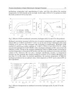
4. Environmental effects and performance limitations
RFID tag performance can be affected by many factors. In particular, the electrical properties
of objects near or in contact with the tag antenna will be changed. A tag is usually attached
directly to the object to be identified. Many common materials, including metals and liquids,
have strong effects on the performance of UHF tag antenna (Dobkin & Weigand, 2005). The
effect of different materials has been studied where the RFID tags can be placed in free space
(air), on cardboard, directly to metal, on plastic container filled with water and on wood
….etc. Figs. 26, 27 and 28 show the effect of some materials on the return loss of some
practical antennas which are mentioned before in this chapter.
Radio Frequency Identification Fundamentals and Applications, Design Methods and Solutions
108
Fig. 24. The Basic structure of IFA.
Fig. 24. Planar Inverted-F Antenna.
Fig. 25. Wire-type Inverted-F Antenna.
Antennas of RFID Tags
109
Fig. 26. Effect of different materials on Return loss of the Text Antenna.
Fig. 27. Effect of different materials on Return loss of the Proposed Fractal Dipole antenna
(P3).
Fig. 28. Effect of different materials on Return loss of the Proposed Fractal Loop Antenna.
Radio Frequency Identification Fundamentals and Applications, Design Methods and Solutions
110
The results showed that the performance of the fractal loop antenna is practically accepted
even if the antenna is attached to different materials and has better return loss with
attaching materials when compared with other types.
5. References
Andrenko A. S., (2005). Conformal Fractal Loop Antennas for RFID Tag Applications,
Proceedings of the IEEE International Conference on Applied Electromagnetics and
Communications, ICECom.
, Pages:1-6, Oct. 2008.
Baliarda, C. P.; Romeu J., & Cardama A., M. (2000), The Koch monopole: A small fractal
antenna.
IEEE Trans. on Antennas and Propagation, Vol.48, (2000) page numbers
(1773-1781).
Curty J. P., Declerdq M., Dehollain C. & Joehl N., (2007).
Design and Optimization Of Passive
UHF RFID Systems,
Springer, ISBN: 0-387-35274-0, New Jersey.
Dobkin D. M., Weigand S. M., (2005). Environmental Effects on RFID Tag Antennas,
Proceedings of IEEE Microwave Symposium Digest, June 2005.
Hirvonen M., Pursula P., Jaakkola K., Laukkanen K., (2003). Planar Inverted-F Antenna
For Radio Frequency Identification.
Electronics Letters,Vol. 40, No. 14, (July 2004),
Hunt V., Puglia A. & Puglia M., (2007).
RFID A Guide To Radio Frequency Identification, John
Wiley & Sons Inc., ISBN: 978-0-470-10764-5 ,New Jersey.
Nikitin P. V., Rao K. V. S.,(2006). Performance Limitations of Passive UHF RFID Systems,
Proceedings of IEEE Antennas and propagation Symposium, pp. 1011-1014, July 2006.
Rao K. V. S. , Nikitin P. V. & Lam S. F., (2005). Antenna Design For UHF RFID tags: A
review and a practical application,
IEEE Trans. On Antennas and Propagation.,
Vol
.53, No.12, Dec. 2005, pp. 3870-3876.
Salama A. M. A., Quboa K., (2008a). Text Antenna for Passive UHF RFID Tags,
Proceedings of
The 5
th
Congress of Scientific Research Outlook in the Arab World (Scientific Innovation
and sustained Development)
, Morocco, Oct. 2008, Fez.
Salama A. M. A., Quboa K., (2008b). Fractal Dipoles As Meander Lines Antennas For
Passive UHF RFID Tags,
Proceedings of The IEEE Fifth International Multi-Conference
on Systems, Signals and Devices (IEEE SSD'08)
, Page: 128, Jordan, July 2008.
Salama A. M. A., Quboa K., (2008c). A New Fractal Loop Antenna for Passive UHF RFID
Tags Applications,
Proceedings of the 3
rd
IEEE International Conference on Information
& Communication Technologies: from Theory to Applications (ICTTA'08)
, Page: 477,
Syria, April 2008, Damascus.
Ukkonen L., Sydanheimo L. & Kivikoski M., (2004a). A Novel Tag Design Using Inverted-F
Antenna for Radio Frequency Identification of Metallic Objects,
Proceedings of
IEEE/Sarnoff Symp. On Advances in Wired and Wireless Communication
, pp. 91-94,
April 2004.
Ukkonen L., Engels D., Sydanheimo L. & Kivikoski M., (2004b). Planar Wire-type Inverted-F
RFID Tag Antenna Mountable On Metallic Objects,
Proceedings of IEEE Int. Symp. on
AP-S, Vol. 1, pp. 101–104, June 2004.
Werner D. H. & Ganguly S. (2003). An Overview of Fractal Antenna Engineering Research.
IEEE Antennas and Propagation Magazine, Vol.45, No.1, (Feb. 2003), page numbers
(38-56).
Zhan J. Q., (2006).
RFID Tag Antennas Designed By Fractals and Manufactured By Printing
Technologies, Institute of Communication Engineering, Tatung University
, June 2006.
7
Near Field On Chip RFID Antenna Design
Alberto Vargas and Lukas Vojtech
Czech Technical University in Prague
Czech Republic
1. Introduction
This chapter deals with the designing strategy and process integration for a small On-Chip-
Antenna (OCA) with a small Radio Frequency Identification (RFID) tag on a chip-area 0.64 x
0.64 mm at 2.45 GHz for communication in near field. On the other hand, communication
between Reader device and set of OCA-Tag is based on inductive coupling.
Embedded antenna is an important step down into the route of miniaturisation. A special
micro-galvanic process that can take place on a normal CMOS wafer makes it possible. The
coil could be placed directly onto the isolator of the silicon chip in the form of a planar
(single layer) spiral arrangement and contacted to the circuit below by means conventional
openings in the passivation layer (e.g., Usami, 2004). Dimension of the conductor flows in
the range of 5-10 µm with a layer thickness of 15-30 µm (Finkenzeller, 2003).
Fig. 1. Embedded antenna structure of ultra-small RFID chip.
RF signal can be radiated effectively if the linear dimension of the antenna is comparable
with the wavelength of the operating frequency; however, the wavelength at 2.45 GHz is
12.24 centimetres. Due the size minimization of the transponder (reducing its area), a loop
antenna in the shape of a coil that is resonating have to be used. Since the operating read
range of these tags is relatively small compared to a wavelength, they operate in the near-
field radiation region. The tag made up of OCA is preferred to save a major portion of the
assembly cost in fabrication and it also enhances the system reliability.
Design strategy and communication principles are introduced by the description of its
equivalent circuit parameters. The next step is matching network design and simulation
0.64 mm
0.64 mm
Embedded RF Antenna
Ultra - Small RFID
Chip (µ-chip)
Radio Frequency Identification Fundamentals and Applications, Design Methods and Solutions
112
based on the complex impedance of real RFID chip EM4222 and silicon chip materials
constants. These preliminary steps are presented, the OCA structure design, simulation and
final dimension optimisation duties are performed.
The resulting OCA transponder with an integrated antenna implemented on the chip thus
requires only approx. 0.64 mm2 of silicone. Its small dimensions allow for expansion of
applications used for marking various miniature objects as e.g. minicontainers for chemical
or biological samples. Economical and application reasons force us to modify the existing
object marking technologies. One of the development trends is the miniaturization of
identifiers, and especially the reduction of their price. Low price and miniaturization allow
for production of new RFID technology applications.
2. Tag antenna design
The efficiency of the antenna is limited by its allowable area, which is simply determined by
the underlying tag chip area. The antenna for backscattering model is a far-field one (dipole,
slot or path antenna) and its typical dimension should be λ/2 or λ/4. Understanding a
symbol λ as wavelength. According to these, the size of the antenna should be around
several centimetres. Since the chip dimension is about micrometers, it is too small to use the
backscattering model although it is widely used in 2.45 GHz. In comparison, with an
inductive-coupling model, the dimension of the inductor coils can be very small as in mm
range. Therefore, OCA antenna becomes the best suitable technology to embed into Chip.
As magnetic-coupling model, OCA should be a coil on the Tag, a portion of the transformer,
constructed together with another coil of the Reader collectively, based on Inductive
Coupling technology as shown in figure 3. The tag either receives energy from the Reader or
communicates the signal to Reader through those two coils. High coupling efficiency, or
communication efficiency between the Reader and Tag, can be obtained by optimizing the
design of the antenna coils. In addition to these, OCA’s coil needs to be designed with a
large inductive reactance, in order to obtain a high electric potential induced under a given
intensity of magnetic field, generated by the Reader’s antenna.
Fig. 2. Model scheme of the circuit to design
Going in depth into the entire design of the receiver part or the Tag, as shown in figure 2,
antenna, matching network and doubler rectifier in series are implemented. The antenna
READER
Matching
Network
Rectifier
OCA
Due to obtaining a
high electric
induced potential,
OCA must
designed with
large X
L
.
Matching network
deliver the
maximum
obtainable energy to
the circuit.
CHIP
Near Field On Chip RFID Antenna Design
113
must be matched with the input impedance of the subsequent circuit, Z
RC
, in order to
deliver the maximum obtainable energy to the Chip. Furthermore, this Matching Network
has to be only constructed from capacitors since inductors will share the energy in OCA and
thus reduce the efficiency of the coil. On the other hand, selected Chip contains Doubler
Schottky rectifier (Prat, 1999) and internal capacitance, which are responsible for converting
AC signal into DC. Indeed, not only rectifier capacitance is usually assumed integrated, but
also parasitic capacitances of the Tag’s Chip material.
Fig. 3. Scheme of the Inductive Coupling Technology.
In terms of analysis, load process of the Chip is often modelled by a resistance at its highest
current usage (Atmel, 2002) at power-up reset or during an EEPROM write.
Keeping the resistance of the coil to the minimum permits to enhance the quality factor, Q,
of the antenna and increase the available energy to the Tag. In order to obtain the high
electric potential induced, OCA must be designed with a large inductive reactance.
Furthermore, OCA must be fabricated of a required Q-factor performance to satisfy the
matching, and a rate around 3 is assumed (Guo et al, 2006).
2.1 Parameters
Fig. 4. Schematic diagram of the Reader and the Tag.
Figure 4 shows the equivalent circuit where the Reader and the Tag antennas are magnetically
coupled via mutual inductance, M. The parallel resonant circuit of the antenna’s Tag includes
the inductance of the loop, L
OCA
,
and as well, its own impedance Z
OCA
(1).
Reader
Tag
Magnetic field H
Radio Frequency Identification Fundamentals and Applications, Design Methods and Solutions
114
Z
OCA
= R
OCA
+ j X
OCA
(1)
Voltage induced in the antenna, V
OCA
, involves both the Tag and the Reader coils in a linear
expresion, as it can be check in formula 2. J
reader
is the current throughout the Reader’s
antenna.
/V
OCA
/ = ω K √(L
reader
L
antena
) J
reader
(2)
Where ω is the circular frequency (ω = 2П f) and K is the coupling coefficient between OCA
and reader’s antenna. Power delivered to the Chip (3), understanding loading stage (figure
4) as the set of Matching network, Double rectifier, the Chip and its input voltage is
assumed as follows:
()( )
2
22
1
2
load
load OCA
load OCA load OCA
R
PV
RR XX
=
+++
(3)
()( )
load load
load OCA
OCA load OCA load
RjX
VV
RR jXX
+
=⋅
++ +
(4)
In terms of design process, when the Chip is properly matched with the antenna coil (5), the
maximum voltage (7) and power (6) is delivered to the load.
Z
OCA
=Z
load
*
(5)
22
max
11
88
OCA OCA
load
OCA load
VV
P
RR
== (6)
22
max
1
2
load OCA OCA OCA
OCA
VRXV
R
=+⋅ (7)
According to the Power maximum load and the theory of the
Q-factor in the resonant LC
circuit, detailed below in section 4.1, both factors can be expressed in function of each other.
Thus, the voltage supplied to the load depends on the voltage of the OCA. Achieving a higher
Q-factor is faced, and 3 is assumed optimal value as reported in the initial part of this section.
2
max
1
8
OCA
load OCA
OCA
V
PQ
R
=⋅ (8)
2
1
1
2
load OCA OCA
VQV=+ ⋅
(9)
Finally, signal amplitude on the Reader side, ΔVreader, which is sent back from the Tag to
the Reader is proportional to the current throughout the Reader’s antenna and the OCA’s
Q-
Value:
22
1
2
OCA
reader reader
OCA
MQ
VJ
X
ω
Δ= ⋅ (10)
Near Field On Chip RFID Antenna Design
115
3. Circuit modelling
The suggested design scenario starts with co-designing of the reader’s antenna (L
reader
) and
OCA (L
OCA
) based on the available fabrication technology to meet the required
specifications. Besides, Q-factor for the power conversion is specified on the based of three-
dimensional electromagnetic simulation would determine the Tag’s efficiency. Matching
Network between OCA and Chip takes an important stage and it is considered through
checking the input impedance of the circuit. Overall, goals must meet according to the
specifications provided by manufacturer of the Chip.
Fig. 5. Equivalent Schematic made by lumped elements
3.1 Design goals
Maximum power at the entrance of the Chip from the reader’s antenna takes an important
requirement to face within design process of the antenna. It is a full duplex system; this
means that Tag must be designed to receive and send data, allowing signal communication
between Reader and Chip. The RFID antenna receives signal from the reader’s antenna and
the signal is powering the Chip when OCA delivers voltage enough to wake up the
Integrated Chip. In transmitting mode, Chip is serving as a source and also responsible for
sending out its stored data through the RFID antenna. The most important and critical
design-procedure is transmitting part, to such an extend if the best results in this mode are
achieved, there are also the best outcomes in receiving mode.
The most important tag performance characteristic is read range. One limitation on the
range is the maximum distance from which the tag receives just enough power to turn on
from the reader. Another limitation is the maximum distance from which the reader can
detect this signal from the tag. The read range is the smaller of two distances (typically, the
first one since RFID reader sensitivity is usually high). Because reader sensitivity is typically
high in comparison with the tag, the read range is defined by the tag response threshold.
Read range is also sensitive to the tag orientation, the material of the tag is placed on, and to
the propagation environment. Theoretical read range depends on the power reflection
coefficient and can be calculated using the Friis free-space formula as:
(
)
2
max
1
4
ttr
th
PGG s
r
P
λ
π
−
= (11)
where λ is the wavelength, Pt is the power transmitted by the RFID reader, Gt is the gain of
the transmitting antenna ( PtGt is EIRP, equivalent isotropic radiated power), Gr is the gain
of the receiving tag antenna, Pth is the minimum threshold power necessary to power up
Z
CHIP
Reader
R
OCA
L
reader
L
OCA
Z
S
2
Z
S1
C
V
DC
Z
R
C