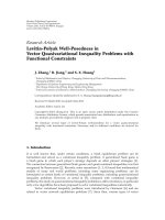
Báo cáo sinh học: " Research Article Efficient Lookup Table-Based Adaptive Baseband Predistortion Architecture for Memoryless Nonlinearity" pdf
Bạn đang xem bản rút gọn của tài liệu. Xem và tải ngay bản đầy đủ của tài liệu tại đây (973.35 KB, 10 trang )
Hindawi Publishing Corporation
EURASIP Journal on Advances in Signal Processing
Volume 2010, Article ID 379249, 10 pages
doi:10.1155/2010/379249
Research Article
Efficient Lookup Table-Based Adaptive Baseband Predistortion
Architecture for Memoryless Nonlinearity
Seydou N. Ba,
1
Khurram Waheed,
2
and G. Tong Zhou
1
1
School of Electrical and Computer Engineering, Georgia Institute of Technology, Atlanta, GA 30332-0250, USA
2
RF-CMOS Radio Design Group of the Wireless Terminals Business Unit, Texas Instruments, Inc., Dallas, TX 75243, USA
CorrespondenceshouldbeaddressedtoSeydouN.Ba,
Received 24 November 2009; Revised 23 March 2010; Accepted 14 May 2010
Academic Editor: Markus Rupp
Copyright © 2010 Seydou N. Ba et al. This is an open access article distributed under the Creative Commons Attribution License,
which permits unrestricted use, distribution, and reproduction in any medium, provided the original work is properly cited.
Digital predistortion is an effective means to compensate for the nonlinear effects of a memoryless system. In case of a cellular
transmitter, a digital baseband predistorter can mitigate the undesirable nonlinear effects along the signal chain, particularly
the nonlinear impairments in the radiofrequency (RF) amplifiers. To be practically feasible, the implementation complexity of
the predistorter must be minimized so that it becomes a cost-effective solution for the resource-limited wireless handset. This
paper proposes optimizations that facilitate the design of a low-cost high-performance adaptive digital baseband predistorter for
memoryless systems. A comparative performance analysis of the amplitude and power lookup table (LUT) indexing schemes is
presented. An optimized low-complexity amplitude approximation and its hardware synthesis results are also studied. An efficient
LUT predistorter training algorithm that combines the fast convergence speed of the normalized least mean squares (NLMSs) with
a small hardware footprint is proposed. Results of fixed-point simulations based on the measured nonlinear characteristics of an
RF amplifier are presented.
1. Introduction
High-efficiency RF amplifiers have nonlinear amplitude and
phase transfer characteristics, which distort the transmitted
signals, causing undesired out-of-band spectral regrowth
and an increase in error vector magnitude (EVM) and
bit error rate (BER). Digital baseband predistortion is an
effective means to reconcile the conflicting requirements of
linearity and power efficiency. For resource-limited low-cost
handsets, the implementation complexity of the predistorter
must be minimized. This paper proposes optimizations that
facilitate the design of a cost-effective and high-performance
adaptive digital baseband predistorter, while minimizing
expensive factory calibration requirements. These attributes
render this work highly desirable to meet the stringent linear-
ity requirements of the modern third and fourth generation
(3G/4G) wireless systems, which employ complex amplitude
and phase domain modulations to achieve superior spectral
efficiency [1].
While 2.5G EDGE and 3G WCDMA voice waveforms
used simpler modulation schemes that exhibited less than
3.5 dB of peak-to-average power ratio (PAPR), advanced
WCDMA (or HSPA) waveforms exhibit PAPRs in excess of
6 dB and modern 4G (LTE, WiMax) use more complex signal
constellations resulting in PAPRs of up to 12 dB [1]. Such a
high PAPR mandates higher linearity requirements from the
RF physical layer, which is in sharp contrast to the stronger
demand for increased power efficiency and maximization of
the handset battery life. These conflicting requirements can
be tamed by resorting to the use of RF front-end amplifiers
in their most power-efficient regime, while using signal
predistortion schemes to achieve the desired linearity.
The nonlinear gain and phase distortions of RF ampli-
fiers are a strong function of the envelope fluctuations in
an RF signal [2, 3]. Consequently, most digital baseband
predistorters are implemented as a function of the amplitude
of the baseband input. In the case of the complex-gain
lookup table (LUT) predistorter [4, 5], the most significant
bits (MSBs) of the signal magnitude can be directly used to
address the physical memory containing the LUT entries. For
example, the first seven MSBs can be used to address an LUT
with 128 entries [6]. The precise amplitude computation
2 EURASIP Journal on Advances in Signal Processing
requires a square-root operation, which is not directly
amenable to efficient hardware implementation, especially
at very high processing rates. A square-root approximation
proposed in [7] has a performance close to the ideal
amplitude calculation. But in addition to the squared magni-
tude computation, the square-root approximation requires
additional LUTs and a linear interpolation calculation.
Other practical digital baseband predistorters [4]havebeen
implemented as a function of the instantaneous envelope
power I
2
+ Q
2
,whereI is the inphase, Q is the quadrature
component of the complex baseband signal. The resulting,
but often unintended effect, is a concentration of the LUT
entries around the higher amplitude region [7, 8]. This
power indexing scheme is suitable for class-A and mild class-
AB amplifiers since their characteristics are mostly linear
until close to saturation. However, this is not well suited to
amplifiers with higher power efficiency, such as deep class-
AB, class-B, C, and E [9], which exhibit significant nonlinear
amplitude and phase distortions across the entire amplitude
range. A comparative performance analysis of the amplitude-
and power-indexing schemes will be presented in this paper.
A suitable low-complexity amplitude approximation for
digital baseband predistorters is then applied. The proposed
amplitude approximation has lower complexity than the
squared magnitude computation and a performance that is
close to the ideal amplitude-indexed LUT predistorter.
Furthermore, the nonlinear characteristics of power
amplifiers can display significant variations when the oper-
ating temperature fluctuates and as the device ages. To
maintain effectiveness of the predistorter and minimize
residual distortions as well as calibration requirements, an
adaptive predistorter [2, 10] must be used. This problem is
further exacerbated by the high PAPR of the modern 3G/4G
modulation waveforms. In this paper, an efficient least mean
squares (LMS)-based [11] adaptation technique for LUT
predistorters is presented as well as its optimization for low
complexity hardware implementation.
Section 2 presents a comparative performance analy-
sis between amplitude and power LUT indexing schemes
and studies the design and implementation of a suitable
amplitude approximation for digital baseband predistorters.
Section 3 presents a low-complexity training approach for
LUT-based complex-gain predistorters.
2. Performance of Amplitude and Power
LUT Indexing
The indexing of a predistorter LUT with the squared signal
magnitude is an attractive approach because of the relative
ease of computation of I
2
+ Q
2
. But it is reported in [7]
that the magnitude indexing generally results in significantly
better performance for a given LUT size. The performance
gap is further exacerbated when the source signal is scaled
for the purpose of power control. An LUT-based square-root
approximation proposed in [7]hasaperformancethatis
close to the ideal amplitude calculation. In this section, we
show that an accurate magnitude approximation for digital
baseband predistorters, with lower hardware footprint, can
be obtained directly from the inphase and quadrature
components of the input signal.
Simple amplitude approximation techniques have been
used for radar detection applications [12–15]. Most of the
methods presented result in relatively coarse approxima-
tions, even though their precision is within the tolerance
of the target applications. But since the digital baseband
predistorter is located in the direct transmit path, such large
amplitude approximation errors would severely limit the
performance of the predistorter, resulting in both residual
EVM degradation and spectral distortions.
The general approach to linear amplitude approximation
is explained in [13]. It consists of rotating the complex input
signal X
= I + jQ such that its phase lies in [0,π/4], then
computing a linear combination of the real and imaginary
parts of the rotated signal Y
= I
r
+ jQ
r
. The rotated signal Y
is given by
I
r
= max
(
|I|, |Q|
)
, Q
r
= min
(
|I|, |Q|
)
.
(1)
It can be easily observed that the magnitude of the rotated
vector Y is equal to the magnitude of the initial vector X:
R
=|Y|=
[
max
(
|I|, |Q|
)
]
2
+
[
min
(
|I|, |Q|
)
]
2
=
|I|
2
+ |Q|
2
=|X|.
(2)
The approximated amplitude is then obtained by evaluating
a linear combination of the real and imaginary parts of Y:
R = aI
r
+ bQ
r
with a, b ≥ 0.
(3)
In [13], the approximation accuracy is improved by
further dividing the angular interval [0, π/4] into two
intervals, and using two different sets of coefficients (a
k
, b
k
),
k
∈{1, 2}that are optimized for their corresponding angular
intervals.
This approach can be further extended to arbitrarily
improve the approximation accuracy by increasing the
number of angular intervals N. If the complex input falls
in the kth angular interval, the amplitude approximation is
given by
R
k
= a
k
I
r
+ b
k
Q
r
,forθ
k−1
≤ θ<θ
k
,
(4)
where θ
= arctan(Q
r
/I
r
), θ
k
and θ
k−1
are the threshold angles
delimiting the angular intervals, with θ
0
= 0andθ
N
= π/4.
Figures 1(a) and 1(b) illustrate the use of two and three equal
angular intervals, respectively.
The amplitude error in the kth angular interval can be
computed as
R
−
R
k
= R −
(
a
k
I
r
+ b
k
Q
r
)
= R
(
1 −a
k
cos θ −b
k
sin θ
)
.
(5)
The relative amplitude error in the kth interval ε
k
is given by
ε
k
=
R −
R
k
R
= 1 − a
k
cos θ −b
k
sin θ.
(6)
EURASIP Journal on Advances in Signal Processing 3
Q
I
π
4
θ
1
0
Region 2
Region 1
(a)
Q
I
π
4
θ
2
θ
1
0
Region 3
Region 2
Region 1
(b)
Figure 1: Linear amplitude approximations. (a) Two angular intervals. (b) Three angular intervals.
The amplitude error (6) is a function of the input angle.
The coefficients (a
k
, b
k
) must be chosen to minimize a given
error metric for each angular interval delimited by the angles
θ
k−1
and θ
k
. Assuming that the input angle θ is uniformly
distributed, we can obtain a closed-form solution for the
coefficients (a
k
, b
k
) that minimizes the mean square of the
relative amplitude error ε
k
. The mean squared error J
k
can
be evaluated as follows:
J
k
= E
ε
2
k
=
p
0
θ
k
θ
k−1
ε
2
k
dθ,
(7)
where p
0
= 1/(θ
k
− θ
k−1
). The optimal coefficients are
obtained by setting the partial derivatives of J
k
with respect
to the coefficients a
k
and b
k
to zero. Taking the partial
derivative of the mean squared error J
k
with respect to the
coefficient a
k
gives
∂J
k
∂a
k
= p
0
θ
k
θ
k−1
∂ε
2
k
∂a
k
dθ
= p
0
θ
k
θ
k−1
2ε
k
∂ε
k
∂a
k
dθ
= 2p
0
θ
k
θ
k−1
a
k
cos
2
θ + b
k
cos θ sin θ −cos θdθ
= p
0
θ
k
θ
k−1
a
k
(
1+cos2θ
)
+ b
k
sin 2θ − 2cosθdθ
=
p
0
2
a
k
(
2Δθ
k
+ α
k
)
+ b
k
β
k
−4c
k
,
(8)
where
α
k
= sin 2θ
k
−sin 2θ
k−1
, c
k
= sin θ
k
−sin θ
k−1
,
β
k
= cos 2θ
k−1
−cos 2θ
k
, Δθ
k
= θ
k
−θ
k−1
.
(9)
Similarly, taking the partial derivative with respect to b
k
gives
∂J
k
∂b
k
=
p
0
2
b
k
(
2Δθ
k
−α
k
)
+ a
k
β
k
−4d
k
, (10)
with
d
k
= cos θ
k−1
−cos θ
k
.
(11)
Setting the partial derivatives to zero yields
⎡
⎣
2Δθ
k
+ α
k
β
k
β
k
2Δθ
k
−α
k
⎤
⎦
⎡
⎣
a
k
b
k
⎤
⎦
=
4
⎡
⎣
c
k
d
k
⎤
⎦
. (12)
It should be noted that since 0
≤ θ
k
≤ π/4andθ
k
>θ
k−1
,
the coefficients α
k
, β
k
, c
k
and d
k
are all strictly positive. The
optimal coefficients for the kth angular interval are obtained
by solving the above system of linear equations (12),
⎡
⎣
a
k
b
k
⎤
⎦
=
2
h
k
⎡
⎣
(
2Δθ
k
+ α
k
)
c
k
−β
k
d
k
(
2Δθ
k
−α
k
)
d
k
−β
k
c
k
⎤
⎦
, (13)
with h
k
= 2Δθ
2
k
+cos(2Δθ
k
) − 1. For any angular interval
delimited by the angles θ
k−1
and θ
k
, the relatively simple
closed-form solution (13) can be evaluated to find the
optimal coefficients (a
k
, b
k
) in the mean squared error sense.
Figure 2 shows the mean squared and peak errors of ε as
the number of angular intervals is increased from N
= 1to
N
= 8.
These results show that the use of three angular intervals
is sufficient to decrease the mean square of the relative
amplitude error below
−50 dB. This ensures that there is
negligible transmit EVM and ACLR contribution due to the
predistorter implementation. As shown by these results, an
arbitrary amplitude approximation accuracy can be achieved
by selecting a large enough number of angular intervals.
But a larger number of angular intervals will result in a
more complex decision process and the approximation is
useful only if it is amenable to efficient implementation. It
should be noted that the optimal coefficients obtained here
are based on the assumption that the phase of the input signal
is uniformly distributed. This assumption applies very well
to most signal modulations. In the special case of a skewed
phase probability density, the true optimal coefficients can
be better approached using unequal angular intervals.
For practical implementation, the approximation based
on three angular intervals is chosen. The angular intervals
are equally spaced. The threshold angles are θ
1
= π/12, and
θ
2
= π/6. For each input sample (I
r
+ jQ
r
), the corresponding
4 EURASIP Journal on Advances in Signal Processing
Table 1: Amplitude approximation over three angular intervals:
amplitude approximation coefficients and resulting relative ampli-
tude errors for floating-point and fixed-point implementations.
Quantities Floating-point Fixed-point
[a
1
a
2
a
3
][0.994 0.927 0.796] [1 60/64 51/64]
[b
1
b
2
b
3
][0.131 0.384 0.610] [6/64 23/64 39/64]
tan(θ
1
)0.268 1/4
tan(θ
2
)0.577 9/16
ε
peak
(%) 0.572 0.712
ε
mean
(%) 0.001 0.082
ε
rms
(%) 0.256 0.306
ε
peak
= max |ε
m
|, ε
mean
= (1/M)
ε
m
,andε
rms
= (1/M)
ε
2
m
.
ε
m
istherelativeamplitudeerrorforthemth input.
M
= 1000 is the total number of test samples.
Table 2: EVM and ACLR performances of an LUT predistorter with
amplitude versus power indexing; the input is WCDMA.
DPD
Status
Indexing Scheme
EVM
(dB)
ACLR1
(dBc/Hz)
ACLR2
(dBc/Hz)
DPD OFF — −21.71 −32.18 −49.81
DPD ON Power
−44.71 −53.60 −53.86
DPD ON Amplitude approx
−61.57 −67.86 −69.95
DPD ON Amplitude ideal
−63.60 −68.99 −71.68
angular interval is determined by comparing Q
r
to I
r
tan(θ
k
)
since tan(
·) is a monotonic function in the interval [0, π/4]
θ<θ
k
=⇒ tan
(
θ
)
< tan
(
θ
k
)
=⇒ Q
r
<I
r
tan
(
θ
k
)
.
(14)
For efficient hardware implementation, we select tan(θ
1
) =
1/4 and tan(θ
2
) = 9/16. The coefficients obtained from
(13) are quantized to six bits of resolution. For best results,
the quantized coefficients a
k
are used to generate new
suboptimal coefficients b
k
, which are in turn quantized. This
two-step process results in a slightly better performance than
the direct quantization of the coefficients a
k
and b
k
.The
coefficients and error characteristics of the floating point
and quantized amplitude approximations are summarized
in Tab le 1 . We observe that the fixed-point approximation
has the advantage of being more practical with a smaller
hardware footprint, while achieving a performance that is
very close to that of the floating-point approximation. Note
that the difference in ε
rms
for the floating- versus fixed-
point implementation is caused by the round-off errors
implemented in the fixed-point hardware.
The performance of the fixed-point amplitude approx-
imation was simulated within a SIMULINK model of a
complete transmitter including predistortion. The amplifier
model is based on the extracted AM-AM and AM-PM
characteristics of a class-E amplifier [16, 17]. The real
and imaginary parts of the class-E amplitude-dependent
complex-gain g(
·) are shown in Figure 3 or three different
temperature settings. The nominal curve at 25
◦
Cisusedfor
the purpose of the present experiment.
−70
−60
−50
−40
−30
−20
Mean and peak error (dB)
12345678
Number of angular intervals
Peak error
MSE error
Figure 2: Mean squared and peak error (ε
k
) as a function of the
number of angular intervals N.
−2
−1
0
R[g(r)]
00.20.40.60.81
Amplitude
−1.5
−1
−0.5
0
[g(r)]
Imaginary gain
Real gain
−35
◦
C
25
◦
C
105
◦
C
Figure 3: Real and imaginary parts of a class-E amplifier nonlinear-
ity expressed as a complex-gain, over different temperature settings.
A linearly interpolated complex-gain LUT with 64 entries
was used to predistort the class-E amplifier. A WCDMA rel.
8 HSUPA-compliant 64QAM signal, with >6.5 dB composite
PAPR is used as input. The input signal (I/Q) resolution
was set to 13 bits and a 3 dB backoff was selected. The
EVM and adjacent channel leakage ratios (ACLRs) at 5 MHz
offset (ACLR1) and 10 MHz offset (ACLR2) are shown
in Ta bl e 2. The ACLR1 and ACLR2 are measured in dBc
across a 5 MHz channel bandwidth. The EVM resulting from
the use of the amplitude indexing is nearly 17 dB lower
than that of the power indexing, and only 2 dB higher
than that of the ideal amplitude indexing. The ACLR1 and
ACLR2 measurements show more than 14 dB improvement
when using the amplitude approximation instead of the
power indexing. Figure 4 shows the WCDMA power spectral
density (PSD) resulting from the above experiment. It is
observed that the spectral regrowth is effectively reduced by
the predistorters. The higher spectral floor resulting from
the power indexing scheme indicates its relatively strong
sensitivity to LUT quantization errors.
EURASIP Journal on Advances in Signal Processing 5
Table 3: Nand2-equivalent gate count for power index computa-
tion and amplitude approximation.
I/Q resolution (bits)
Gate count
Power indexing Amplitude approx
8 1135 1248
10 1884 1629
12 2778 1970
14 3853 2324
−70
−50
−30
−10
WCDMA PSD (dBc/Hz)
−10 −50 5 10
Frequency (MHz)
DPD OFF
Power-index
Ideal amp-index
Approx amp-index
Figure 4: PSD performances of an LUT predistorter using ideal
amplitude indexing, amplitude indexing with approximation, or
power indexing. Input signal is WCDMA.
The fixed-point coefficients and angular thresholds are
chosen to minimize the hardware implementation complex-
ity while maintaining an approximation error close to the
optimum. The diagram of Figure 5 illustrates a possible
implementation.
This design requires two conditional two’s complement
operations to implement the abs(
·) function, three compara-
tors, and four two-to-one multiplexers. The coefficients were
chosen to minimize the complexity of the scaling operations.
To achieve a fair comparison, the implementation complex-
ity of the amplitude approximation must be compared to
that of the instantaneous power computation (I
2
+ Q
2
).
Both options were implemented in VHDL and synthesized
with the Synopsys Design Compiler. The resulting nand2-
equivalent gate count is obtained for different resolutions
of the inphase/quadrature components (I/Q). The synthesis
results are summarized in Ta bl e 3.
It is clear from these results that the amplitude approx-
imation design results in lower gate count for the input
signal resolutions of interest (>10 bits). The gap between the
amplitude-indexing and power-indexing schemes increases
rapidly as the resolution is increased from 8 to 14 bits. For
input resolutions lower than 8 bits, the power computation
results in a slightly lower gate count. But at such low
resolutions, the performance is primarily limited by the
I/Q signal quantization error. In this case, the resolution
of the (a
k
,b
k
)coefficients can be reduced down to 5 or
4 bits to further reduce the gate count of the amplitude
approximation block. Typically, a baseband signal resolution
of more than 10 bits is required to meet the close-in spectrum
and waveform quality specifications over the entire power
control dynamic range as per the standard’s requirements.
Therefore, the proposed amplitude approximation design
has a clear advantage over the power indexing, both in terms
of total design area and performance.
3. Adaptation of Complex-Gain LUT
Predistorters
In [4], Cavers proposed the secant update for fast adap-
tation of complex-gain LUT predistorters. But its high
computational complexity makes it unsuitable for hardware
implementation.
The indirect learning architecture [18]isillustratedin
Figure 6. A replica of the feedforward predistorter is trained
in the feedback path as the postinverse of the amplifier
nonlinearity. The updated LUT is periodically copied to
the feedforward predistorter. This configuration has the
advantage of decoupling the transmit path from the update
branch. The transmitted signal is therefore isolated from any
impulse noise in the feedback path at the cost of replicating
the predistorter.
The LUT is an array of L complex-gain entries F
[n]
corresponding to the input amplitudes r
n
. If the LUT is not
interpolated, the nth LUT entry is selected for all feedback
signals y
k
in the interval defined by
r
n
+ r
n−1
2
≤
y
k
<
r
n
+ r
n+1
2
.
(15)
For every signal sample y
k
in this interval, an error signal e
k
is generated,
e
k
= z
k
−F
[n]
y
k
.
(16)
The nth entry F
[n]
can be updated using the LMS algorithm
as follows:
F
[n]
k+1
= F
[n]
k
−μ
∂e
∗
k
e
k
∂F
[n]
.
(17)
It should be noted that
|e
k
|
2
is not a holomorphic function
and therefore does not have a complex derivative. For the
purpose of the steepest-descent algorithm, the complex
gradient with respect to the complex gain F
[n]
can be defined
as the combination of the partial derivatives with respect to
the real and imaginary parts of F
[n]
[19]:
∂e
∗
k
e
k
∂F
[n]
=
1
2
∂e
∗
k
e
k
∂R
F
[n]
+ j
∂e
∗
k
e
k
∂I
F
[n]
, (18)
where R
{·} and I{·}, respectively, designate the real and
imaginary parts of the argument. Substituting (18) into (17)
and carrying out the partial derivatives yields
F
[n]
k+1
= F
[n]
k
+ μy
∗
k
e
k
.
(19)
6 EURASIP Journal on Advances in Signal Processing
I
abs
0
1
I
r
L
>
R
Q
abs
0
1
Q
r
1
4
×
9
16
L
>
R
L
>
R
×
0
1
1
60
64
0
51
64
1
×
R
+
×
6
64
23
64
39
64
0
1
0
1
Figure 5: Implementation of the amplitude approximation with three angular intervals.
Complex baseband input
x
×
|·|
τ
d
G
Nonlinearity
F
1/K
+
+
−
e
×
y
|·|
F
Periodic copy
z
y
Figure 6: Adaptation of complex-gain LUT predistorters using the
indirect learning architecture.
The gradient definition in (18) is equivalent to separately
deriving the LMS algorithm for the real and imaginary
parts of the complex-gain predistorter, respectively [20].
Considering one single interval at a time allows to simplify
the problem by reducing it to finding an approximate inverse
of the average amplifier complex gain within the considered
interval. For each incoming feedback sample, only the
corresponding entry that is addressed by its magnitude
is updated. This process is similar to the partial update
LMS [21, 22]. The update operation requires two complex
multiplies (one to compute the error e
k
and one to evaluate
the gradient), two additions and the scaling by μ, which can
be simplified if it is restricted to powers of two. The update
system is stable provided that 0 <μ<2/λ
2
n
[23], with λ
2
n
being equal to E[|y
k
|
2
]forally
k
falling in the nth interval.
If the LUT size is large, the samples y
k
can be assumed to
have a uniform distribution across the interval. In this case,
the expectation can be approximated by the square of the
average magnitude, which is the point located at the center
of the interval: λ
2
n
≈|y
n
|
2
.
If the regular LMS update equation (19) is used, the
convergence speed will vary across the table entries. The
upper entries will converge significantly faster than the lower
entries. To avoid this issue, the normalized LMS (NLMS)
algorithm [24, 25]canbeused,
F
[n]
k+1
= F
[n]
k
+
μ
y
k
2
y
∗
k
e
k
.
(20)
The NLMS update of (20) results in faster and uniform
convergence of the entries across the LUT. But its direct
implementation has two limitations.
(i) For very low values of
|y
k
| the system becomes
susceptible to noise in the feedback path, with a
potential to drive the update system into instability.
(ii) The scaling by the magnitude is an expensive
operation that is not directly amenable to efficient
hardware implementation.
An approximation of the NLMS similar to the clipped
LMS algorithm [26–28] is proposed. This approach, termed
low-complexity normalized LMS (LCNLMS), is suitable for
efficient hardware implementation and maintains the fast
convergence of the NLMS. First, the update equation of (20)
can be conveniently reformulated as follows:
F
[n]
k+1
= F
[n]
k
+
μ
y
k
y
∗
k
y
k
e
k
= F
[n]
k
+ μ
k
e
jφ
k
e
k
,
(21)
where φ
k
= ∠y
∗
k
is the complex argument of y
∗
k
and
μ
k
= μ/|y
k
|. It is clear from this incremental update that
the NLMS is equivalent to using a variable update coefficient
that is inversely proportional to the input amplitude
|y
k
|and
replacing the complex multiply with a rotation of the error by
φ
k
. The computational complexity of the rotation operation
can be greatly simplified by quantizing the angle φ
k
.Todo
EURASIP Journal on Advances in Signal Processing 7
Amplitude bits
MSB
a
11
a
10
a
9
a
8
a
7
a
6
a
5
Detects position of highest
amplitude bit
Base-two exponent
bits
η
k
b
0
b
1
b
2
MSB
One-hot vector to log
base-two encoder
Figure 7: Circuit that generates the base-two exponent η
k
.
so, let us define the sign function sgn(·) corresponding to
the sign bit in the two’s complement representation as
sgn
(
x
)
=
⎧
⎨
⎩
+1, if x ≥ 0,
−1, if x<0.
(22)
Let S
I
and S
Q
, respectively, be the signs of the real and
imaginary parts of the feedback signal y
k
,
S
I
= sgn
R
y
k
, S
Q
= sgn
I
y
k
.
(23)
Quantization of the angle φ
k
can be achieved by using the
following update equation:
F
[n]
k+1
= F
[n]
k
+ μ
k
S
I
− jS
Q
e
k
= F
[n]
k
+ μ
k
±1 ± j
e
k
= F
[n]
k
+
√
2μ
k
e
jmπ/4
e
k
,
(24)
with
m
= S
Q
(
S
I
−2
)
.
(25)
The phase φ
k
is therefore quantized to four possible values,
that is, φ
k
∈{±π/4,±3π/4},thuseffectively eliminating one
complex multiplier (or four real multipliers).
The amplitude-dependent coefficient μ
k
could be imple-
mented as a lookup table with one coefficient per table entry.
To minimize the required memory space and further reduce
the implementation costs, μ
k
canbeconstrainedtopowersof
two and generated from the magnitude
|y
k
| as follows:
u
k
= 2
η
k
with η
k
= min
−
log
2
y
k
, η
0
, (26)
where
· stands for the ceil(·) rounding function (round to
the nearest integer towards infinity) and η
0
is an arbitrary
integer. In the above expression, it is assumed without loss
of generality that the signal is normalized such that
|y
k
| < 1.
Forcing the maximum exponent to η
0
sets a maximum value
for μ
k
to prevent any instability caused by the sensitivity
to noise at low amplitudes. The base-two exponent η
k
can
be very efficiently generated with the simple combinatorial
circuit illustrated in Figure 7. The amplitude is represented
with 12 bits of resolution and the exponent η
k
is represented
with a three-bit binary word. This is equivalent to setting
η
0
= 7. The first stage of the circuit outputs a one-hot binary
vector (i.e., only one bit is set at a time) corresponding to the
position of highest nonzero amplitude bit. The second stage
encodes the position of the nonzero bit into a binary number,
effectively computing a rounded base-two logarithm of the
input amplitude. The scaling by μ
k
can be implemented by a
simple binary shifter.
The combinatorial logic implementation of the
amplitude-dependent update coefficient lacks flexibility
since the update speed cannot be changed. This issue can be
tackled by introducing an additional coefficient μ
a
that is
programmable,
F
[n]
k+1
= F
[n]
k
+ μ
a
μ
k
S
I
− jS
Q
e
k
.
(27)
It should be noted that this low complexity update is even
simpler to realize in hardware than the regular LMS, which
requires two complex multipliers and has a much slower
convergence speed.
This low-complexity update method (LCNLMS) was
simulated and compared to the LMS and the NLMS.
The previously described class-E amplifier is used in this
experiment and a 10 MHz LTE signal with a composite PAPR
of 8.5 dB is used to train the feedback LUT in the indirect
learning setup. The size of the complex-gain LUTs is set to
L
= 64 entries. The complex-gain LUT entries are initially
set to unity, which is functionally equivalent to bypassing the
8 EURASIP Journal on Advances in Signal Processing
−50
−40
−30
−20
−10
0
MSE
LUT
(dB)
5 101520253035404550
Iterations (K samples)
LMS
NLMS
LCNLMS
Figure 8: Convergence speed of LMS, NLMS, and LCNLMS.
predistorter. The resolution of the inphase and quadrature
(I/Q) signal components is set to 13 bits. To measure the
sensitivity of the adaptation to noise, the feedback signal is
corrupted by additive white Gaussian noise (AWGN) and has
an SNR of 33 dB. The LUT is updated at a rate of 30.76 MHz
and the overall simulation was run at a sampling rate of
61.52 MHz. The update coefficient μ for LMS and NMLS is
set to μ
= 1/16. Comparing (21)and(24) shows that the
LCNLMS intrinsically increases the update rate by a factor of
√
2. On the other hand, the biased quantization of η
k
in (26)
approximately compensates for this factor. Therefore, setting
μ
a
= 1/16 for the LCNLMS ensures a fair comparison.
Figure 8 compares the convergence of the regular LMS,
the NLMS, and the proposed LCNLMS. It shows the
instantaneous mean squared error MSE
LUT
between the
updated LUT F and an optimal reference LUT H obtained
via least-square approximations in each interval
MSE
LUT
=
1
L
L
n=1
F
[n]
−H
[n]
2
.
(28)
These results show that the convergence speed of the
proposed LCNLMS is close to that of the NLMS. It should
also be noted that the LCNLMS leads to an implementation
complexity even lower than the generic LMS.
The adaptation was disabled after 5 ms and the trained
LUT was used in the feedforward path. The resulting
output PSDs are shown in Figure 9. The LCNLMS has the
same performance as the NLMS. Despite the relatively long
training time, the lower entries of the LMS-trained LUT
did not converge, which explains the poor performance
compared to the NLMS and LCNLMS.
3.1. Updating a Linearly-Interpolated LUT. Linear interpo-
lation greatly reduces the LUT approximation errors and
enables significant reduction of the required LUT size [6, 29].
If linear interpolation is used, for each feedback sample
−70
−60
−50
−40
−30
−20
−10
0
LT E P S D ( d Bc / Hz )
−20 −15 −10 −50 5 101520
Frequency (MHz)
DPD OFF
LMS
NLMS
LCNLMS
Figure 9: PSD performances of a complex-gain LUT predistorter
trained using LMS, NLMS, and LCNLMS. Input signal is 10 MHz
LTE signal.
magnitude |y
k
| falling between addresses n and n + 1, the
interpolated complex-gain is
F
k
= F
[n]
+ γ
k
F
[n+1]
−F
[n]
, (29)
where γ
k
is the interpolation factor. For the purpose of prac-
tical implementation, the address n and the interpolation
factor γ
k
are readily obtained from the amplitude bits
y
k
=⇒
a
11
a
10
a
09
a
08
a
07
a
06
address bits (n)
a
05
a
04
a
03
a
02
a
01
a
00
interpolation factor (γ
k
)
.
(30)
It should be noted that for each input sample, two
consecutive LUT entries must be fetched from memory and
interpolated to compute the complex-gain. The hardware
implementation and the sequencing of operations can be
greatly simplified by using a dual-port memory. In general,
dual-port memories are more expensive and larger in size
than single-port memories of the same capacity. But in the
case of the LUT interpolation, the two entries to be fetched
are always located at consecutive addresses. Consequently,
a dual-port memory of size L can be emulated using two
single-port memory blocks of size L/2 and simple additional
logic. One of the blocks stores the entries located at even
addresses, and the other one stores the entries at odd
addresses. This process allows the implementation of a
pseudo dual-port memory at the same cost as a single-port
memory. The only limitation is that simultaneous read/write
operations require one address to be odd and the other
to be even. In the case of a linearly interpolated LUT, this
requirement is always satisfied because the addresses n and
n + 1 are consecutive. If linear interpolation is used in the
feedback path (or updated LUT), the error signal e
k
is given
by
e
k
= z
k
−F
k
y
k
= z
k
−
1 −γ
k
F
[n]
−γ
k
F
[n+1]
y
k
.
(31)
EURASIP Journal on Advances in Signal Processing 9
0.5
0.6
0.7
0.8
|LUT|
10 20 30 40 50 60
LUT index
LIN LUT
ZOH LUT
Figure 10: Converged LUT Predistorters using LCNLMS with
linear (LIN) and nearest-neighbor (ZOH) interpolation in the
feedback predistorter.
Since two entries are used to generate the interpolated
complex-gain, both entries should be updated with each new
data sample. The application of the same LMS algorithm
by alternatively computing the gradients with respect to F
[n]
and F
[n+1]
results in the following update equations:
F
[n]
k+1
= F
[n]
k
+
1 −γ
k
μy
∗
k
e
k
,
F
[n+1]
k+1
= F
[n+1]
k
+ γ
k
μy
∗
k
e
k
.
(32)
Similarly to (27), the LCNLMS can also be applied to the
linearly interpolated case, leading to the following update
equations:
F
[n]
k+1
= F
[n]
k
+
1 −γ
k
μ
a
μ
k
S
I
− jS
Q
e
k
,
F
[n+1]
k+1
= F
[n+1]
k
+ γ
k
μ
a
μ
k
S
I
− jS
Q
e
k
.
(33)
Figure 10 shows that both the nearest neighbor and linear
interpolation adaptations converge to the same solution.
For the same update coefficient μ
a
, the linearly interpolated
adaptation has lower LUT approximation errors and there-
fore, results in a slightly better steady state performance. The
steady state performance of the nearest neighbor adaptation
can generally be improved by decreasing the update coeffi-
cient, at the cost of slower convergence.
Figure 11 uses a 4G LTE 10 MHz single-carrier (orthog-
onal) frequency-division multiple access (SC-FDMA) input
stimulus with greater than 8.5 dB of composite PAPR to illus-
trate the resulting signal PSDs using the nearest neighbor and
the linearly interpolated adaptation schemes. The simulation
setup described in the previous section was reused, where the
root mean square level of the digital signal was adjusted to
account for the higher PAPR of the modulation waveform.
The feedforward predistorter is linearly interpolated in both
cases and the update coefficient is set to μ
a
= 1/16. It
is evident that the close-in performances achieved using
eitherschemearequitecomparable.Thespectralregrowth
is significantly reduced. The spectral floor using ZOH
−70
−60
−50
−40
−30
−20
−10
0
LT E P S D ( d Bc / Hz )
−15 −10 −50 5 1015
Frequency (MHz)
DPD OFF
LIN ADAPT
ZOH ADAPT
Figure 11: PSD performance of a complex-gain LUT predistorter
trained using LCNLMS with linear (LIN) and nearest-neighbor
(ZOH) interpolation in the feedback predistorter. Input waveform
is a 10 MHz LTE OFDM signal.
is 2 to 3 dB higher due to the intrinsic half-bit excess
quantization noise of the ZOH as compared to the linear
interpolation [29].
Therefore, even when the feedforward predistorter is
chosen to be linearly interpolated, the nearest neighbor
adaptation can be used in the update branch of the indirect
learning architecture, without much performance penalty.
Note that ZOH requires only one memory read and write
for each data sample. On the other hand, the linearly
interpolated adaptation requires two memory reads and
writes per data sample, placing more stringent timing
requirements on the adaptation hardware.
4. Conclusions
In this paper, an efficient LUT-based adaptive memoryless
predistorter configuration, with minimized chip area, has
been presented. An amplitude approximation scheme suit-
able for digital baseband predistorters is proposed. A closed-
form solution is derived to determine the optimal param-
eters for the amplitude approximation using any arbitrary
angular interval size. A quantized amplitude approximation
with three angular intervals is implemented in VHDL and
synthesized with the SYNOPSYS DESIGN COMPILER. The
predistorter performance using the proposed area-efficient
scheme is shown to be within 2 dB of the ideal amplitude
performance, while it outperforms the power-indexing in
both design area and rejection of residual distortions by a
wide margin.
An adaptation algorithm for complex-gain LUT predis-
torters based on the indirect learning architecture is also
presented. The proposed adaptation algorithm has been
optimized for efficient hardware implementation. It has a
convergence speed that is comparable to the normalized
10 EURASIP Journal on Advances in Signal Processing
LMS and lends itself to very efficient hardware implemen-
tation. The proposed optimized adaptive predistorter can be
extended to mitigate memory effects by adding a linear time-
invariant filter in cascade with the memoryless complex-gain
predistorter [5, 30].
References
[1] 3rd Generation Partnership Project, (3GPP), March 2010,
/>[2] R. J. P. de Figueiredo, L. Fang, and B. M. Lee, “Design of an
adaptivepredistorter for solid state power amplifier in wireless
OFDM systems,” Research Letters in Signal Processing, vol.
2009, Article ID 515797, 5 pages, 2009.
[3] K. Waheed and S. N. Ba, “Adaptive digital linearization of
a DRP based EDGE transmitter for cellular handsets,” in
Proceedings of the 50th IEEE International Midwest Symposium
on Circuits and Systems (MWCSAS ’07), pp. 706–709, August
2007.
[4] J. K. Cavers, “Amplifier linearization using a digital predis-
torter with fast adaptation and low memory requirements,”
IEEE Transactions on Vehicular Technology,vol.39,no.4,pp.
374–382, 1990.
[5] P. Jardin and G. Baudoin, “Filter lookup table method for
power amplifier linearization,” IEEE Transactions on Vehicular
Technology, vol. 56, no. 3, pp. 1076–1087, 2007.
[6] S. N. Ba, K. Waheed, and G. T. Zhou, “Efficient spacing
scheme for a linearly interpolated lookup table predistorter,”
in Proceedings of IEEE International Symposium on Circuits and
Systems (ISCAS ’08), pp. 1512–1515, May 2008.
[7] L. Sundstr
¨
om, M. Faulkner, and M. Johansson, “Quantization
analysis and design of a digital predistortion linearizer for RF
power amplifiers,” IEEE Transactions on Vehicular Technology,
vol. 45, no. 4, pp. 707–719, 1996.
[8] J. K. Cavers, “Optimum table spacing in predistorting ampli-
fier linearizers,” IEEE Transactions on Vehicular Technology,
vol. 48, no. 5, pp. 1699–1705, 1999.
[9] P. B. Kenington, High Linearity RF Amplifier Design,Artech
House Publishers, Norwood, Mass, USA, 2000.
[10] K. C. Lee and P. Gardner, “Comparison of different adap-
tation algorithms for adaptive digital predistortion based on
EDGE standard,” in Proceedings of IEEE MTT-S International
Microwave Symposium Digest, vol. 2, pp. 1353–1356, May
2001.
[11] B. Widrow and S. Stearns, Adaptive Signal Processing, Prentice
Hall, Englewood Cliffs, NJ, USA, 1985.
[12] M. Onoe, “Fast amplitude approximation yielding either
exact meanor minimum deviation for quadrature pairs,”
Proceedings of the IEEE, vol. 60, no. 7, pp. 921–922, 1972.
[13] A. E. Filip, “A baker’s dozen magnitude approximations and
their detection statistics,” IEEE Transactions on Aerospace and
Electronic Systems, vol. 12, no. 1, pp. 86–89, 1976.
[14] F. Braun and H. Blaser, “Digital hardware for approximating
the amplitude of quadrature pairs,” Electronics Letters, vol. 10,
no. 13, pp. 255–256, 1974.
[15] A. E. Filip, “Linear approximations to
x
2
+ y
2
having
equiripple error characteristics,” IEEE Trans Audio Electroa-
coust, vol. AU-21, no. 6, pp. 554–556, 1973.
[16] W. A. Tsou, W. S. Wuen, T. Y. Yang, and K. A. Wen, “Analysis
and compensation of the AM-AM and AM-PM distortion for
CMOS cascode class-E power amplifier,” International Journal
of Microwave Science and Technology, vol. 2009, Article ID
597592, 9 pages, 2009.
[17] P. Cruise, C M. Hung, R. B. Staszewski et al., “A digital-to-RF-
amplitude converter for GSM/GPRS/EDGE in 90-nm digital
CMOS,” in Proceedings of IEEE Radio Frequency Integrated
Circuits Symposium (RFIC ’05), vol. RMO1A-4, pp. 21–24,
June 2005.
[18] C. Eun and E. J. Powers, “A new volterra predistorter based on
the indirect learning architecture,” IEEE Transactions on Signal
Processing, vol. 45, no. 1, pp. 223–227, 1997.
[19] D. H. Brandwood, “A complex gradient operator and its
application in adaptive array theory,” IEE Proceedings F, vol.
130, no. 1, pp. 11–16, 1983.
[20] B. Widrow, J. McCool, and M. Ball, “The complex LMS
algorithm,” Proceedings of the IEEE, vol. 63, no. 4, pp. 719–720,
1975.
[21] S. C. Douglas, “Adaptive filters employing partial updates,”
IEEE Transactions on Circuits and Systems II,vol.44,no.3,pp.
209–216, 1997.
[22] P. Ramos, R. Torrubia, A. L
´
opez, A. Salinas, and E. Masgrau,
“Step size bound of the sequential partial update LMS
algorithm with periodic input signals,” EURASIP Journal on
Audio, Speech, and Music Processing, vol. 2007, Article ID
10231, 15 pages, 2007.
[23] B. Widrow and E. Walach, “On the statistical efficiency of the
LMS algorithm with nonstationary inputs,” IEEE Transactions
on Information Theory, vol. 30, no. 2, pp. 211–221, 1984.
[24] G. C. Goodwin and K. S. Sin, Adaptive Filtering Prediction and
Control, Prentice Hall, Englewood Cliffs, NJ, USA, 1984.
[25] T. Aboulnasr and K. Mayyas, “Complexity reduction of
the NLMS algorithm via selective coefficient update,” IEEE
Transactions on Signal Processing, vol. 47, no. 5, pp. 1421–1424,
1999.
[26] J. L. Moschner, Adaptive filtering with clipped input data,Ph.D.
dissertation, Stanford University, Stanford, Calif, USA, June
1970.
[27] M. Lotfizad and H. S. Yazdi, “Modified clipped LMS algo-
rithm,” EURASIP Journal on Applied Signal Processing, vol.
2005, no. 8, pp. 1229–1234, 2005.
[28] L. Crum and S. Wu, “Convergence of the quantizing learning
method forsystem identification,” IEEE Transactions on Auto-
matic Control, vol. 13, no. 3, pp. 297–298, 1968.
[29]S.N.Ba,K.Waheed,andG.T.Zhou,“Optimalspacingof
a linearlyinterpolated complex-gain LUT predistorter,” IEEE
Transactions onVehicular Technology, vol. 59, no. 2, pp. 673–
681, 2010.
[30] L. Ding, R. Raich, and G. T. Zhou, “A hammerstein predis-
tortion linearization design based on the indirect learning
architecture,” in Proceedings of IEEE International Conference
on Acoustic, Speech, and Signal Processing (ICASSP ’02), vol. 3,
May 2002.