Báo cáo hóa học: " On the Morphology, Structure and Field Emission Properties of Silver-Tetracyanoquinodimethane Nanostructures" pptx
Bạn đang xem bản rút gọn của tài liệu. Xem và tải ngay bản đầy đủ của tài liệu tại đây (652.02 KB, 6 trang )
NANO EXPRESS
On the Morphology, Structure and Field Emission Properties
of Silver-Tetracyanoquinodimethane Nanostructures
Chunnuan Ye
•
Kaibo Zheng
•
Wenlong You
•
Guorong Chen
Received: 22 April 2010 / Accepted: 7 May 2010 / Published online: 22 June 2010
Ó The Author(s) 2010. This article is published with open access at Springerlink.com
Abstract Silver-tetracyanoquinodimethane(Ag-TCNQ)
nanostructured arrays with different morphologies were
grown by an organic vapor-transport reaction under different
conditions. The field emission properties of nanostructured
arrays were studied systematically. Their morphology and
crystal structure were characterized by SEM and XRD,
respectively. It was found that the field emission properties
were strongly dependent on the reaction temperature and the
initial Ag film thickness. The lowest turn-on field with 10-nm-
thick silver film is about 2.0 V/lm, comparable to that of
carbon nanotubes. The film crystal structure and the mor-
phology are contributed to the final emission performance.
Keywords Organic semiconductor Á Nanostructures Á
Ag-TCNQ Á Field emission
Introduction
Field emission is of considerable interest over the past few
years. Especially, various kinds of conventional inorganic
semiconductors have been considered as promising field
emitters to fabricate field emission displays because of
their high enhancement factor, physical and chemical
properties and wide range of possible applications
[1]. However, organic nanostructured materials are
scarcely reported on the field emission properties. Tris
(8-hydroxyquinoline) aluminum (Alq) [2], copper hexa-
deca fluorophthalocyanine (F
16
CuPc) [3], CuPc [3],
copper/silver tetrafluoro tetracyanoquinodimethane (CuT-
CNQF
4
) and AgTCNQF
4
[4] have been reported. It is
especially notable for the M-TCNQF
4
nanostructures,
which exhibit tunable morphologies, high current density
and low turn-on field. But the growth temperature of
M-TCNQF
4
nanostructures is higher than 443 K. M-TCNQ
one-dimensional (1D) nanostructures grown at a lower
reaction temperature have attracted enormous attention due
to their electrical switching effect for memory device
application [5], and large area [6] and enhanced field
emission by a metal buffer layer [7] are reported. It is better
for device on those flexible substrates that the reaction
temperature is relatively low.
However, it is still elusive to understand the relations
between the growth conditions and the emission properties
due to the complex shape and crystalline structure; defects
and interface states. So in this paper, the dependence of
field emission from Ag-TCNQ nanowires on different
growth conditions including reaction temperature, starting
silver film thickness and reaction time span were studied
and discussed according to SEM and XRD characteriza-
tions of the Ag-TCNQ nanostructures in detail.
Experimental
The samples were produced via a vacuum vapor-transport
reaction method developed in our previous work [8]. First,
C. Ye (&)
College of Chemistry, Chemical Engineering and Materials
Science, Soochow University, 215123 Suzhou, People’s
Republic of China
e-mail:
K. Zheng Á G. Chen (&)
Department of Chemistry, Fudan University, 200433 Shanghai,
People’s Republic of China
e-mail:
W. You
School of Physical Science and Technology, Soochow
University, 215006 Suzhou, Jiangsu, People’s Republic of China
123
Nanoscale Res Lett (2010) 5:1307–1312
DOI 10.1007/s11671-010-9643-9
Ag film was thermal evaporated on substrate with base
pressure of 2 9 10
-3
Pa and thickness monitored by an in
situ microbalance of quartz crystal. The metal film on the
substrate together with TCNQ powder (98%, Aldrich) was
then placed in a quartz tube connected to a vacuum
chamber. After pumping down to 2 9 10
-3
Pa, the quartz
tube was sealed and thermal treated in the furnace. After
reacting for some time, the blue-colored film covered on
the substrate was prepared and then taken out for sub-
sequent experiments.
To study the field emission properties of Ag-TCNQ
nanostructures, the morphologies characterization for those
samples grown under different conditions is necessary. The
morphology is characterized by scanning electron micros-
copy (SEM, XL30FEG,PHILIPS, with a resolution of
2 nm). The structure of the as-grown nanostructures is by
X-ray diffraction (XRD, Rigaku D/Max-3C).
Field emission measurements were carried out in a
parallel-plate configuration with the base pressure of
5 9 10
-3
Pa in a vacuum chamber. The nanostructures
sample acted as the cathode, and a steel cylindrical elec-
trode acted as the anode. In this study, the turn-on field is
defined as the applied electric field that can generate a
current density of 10 lA/cm
2
. The cross-sectional area of
the anode is 0.498 cm
2
defined as the field emission area to
obtain the current density.
Results and Discussion
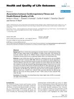
Figure 1 shows the typical top view of the as-deposited
Ag-TCNQ nanowires at 393 and 423 K. As a whole, most
of them are vertical to the substrate with a sharp tip. The
diameter varies from 50 to 150 nm.
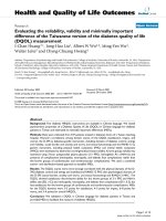
Figure 2 shows the top view for samples with 10, 30 and
50-nm-thick silver films. It is shown that the density of the
nanowires becomes larger, and the orientation perpendicular
to the substrate becomes more regular with the increase in
the film thickness. As shown in the left Fig. 2a, sparse
nanowires are aligned irregularly, reclining or lying. More
nanowires will grow and align more perpendicular to the
substrate due to the space limit effect in a thicker silver film.
For the samples with 30-nm-thick Ag film, the nanowires are
with obviously sharp tips, but the tips are not like that with
50-nm Ag film. Because thicker Ag film will give more and
smaller particles upon heating, and higher rate of diffusion
dominates, the nanowires grow seemingly in succession
without obvious tips on the surface.
In addition, the thickness of silver film greatly influ-
ences the length of as-obtained nanowires. Actually, the
length of the nanowire depends on the thickness as well as
the growth time. Given that the growth reaction is com-
pleted, we observe that the thickness of the pre-deposited
Ag film actually dominates the length of Ag-TCNQ
nanowires from the side-view SEM image of as-obtained
nanowires. First, as the Ag
?
source for nanowire growth is
derived from the pre-deposited Ag film, the thicker film
will provide larger amount of Ag source, which would
extend the reaction time in the process of nanowire growth,
thus Ag-TCNQ with larger length could form. In short, the
thickness of the pre-deposited film is proportional to the
length of as-obtained nanowire. However, when the
thickness is rather high (etc. lm order), the film is unlikely
to melt into molten droplets within the thermal treatment.
Therefore, the VS growth process would be inhabited
resulting in the absence of nanowire to synthesize. The
same results can also be obtained with regard to Cu-TCNQ
counterpart.
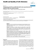
In our experiments, XRD patterns of the as-prepared Ag-
TCNQ at different reaction temperature are shown in Fig. 3.
Those patterns for samples grown at 363 K are indexed
similar to that orthorhombic structure [9] with a = 6.975 A
˚
,
b = 16.686 A
˚
, c = 17.455 A
˚
and V = 2031.5 A
˚
3
, named
phase II. In the sample grown at 373 K, most of phase I is
Fig. 1 SEM top-view images of
Ag-TCNQ nanowires, with
30 nm Ag film at 393 and
423 K, respectively
1308 Nanoscale Res Lett (2010) 5:1307–1312
123
consisted with three preferential growth directions and still
mixed some phase II. And the other samples grown at a
temperature higher than 393 K are indexed to that tetragonal
cell with a = b = 12.142 A
˚
, c = 17.049 A
˚
and
V = 2513.7 A
˚
3
, named phase I, whose structure remains
constant but the preferential growth direction changes a little
from larger to smaller diffraction angle with the reaction
temperature from 393 to 413 K. These results indicate that
the growth of Ag-TCNQ crystals is sensitive to the reaction
temperature.
Because the Ag-TCNQ nanowires with 30-nm-thick Ag
film are with regular array and proper structure of tips, their
field emission properties dependence on the other growth
conditions are first studied in detail. Figure 4 shows the
characteristics of emission current density versus applied
field for them grown under the reaction temperature of 373,
393 and 413 K with 30-nm-thick Ag film, respectively, and
other conditions are the same. With the temperature
increasing, the turn-on field is 2.0, 5.5 and 7.0 V/lm,
respectively. The turn-on field for the former one is lower
than that of the latter two, mainly because they consist of
different crystalline structures recognized by the XRD
analysis shown in Fig. 3. The former one belongs to phase
II mixed with some of phase I and the others completely to
phase I. From this point, we can conclude that the phase I
grown under higher temperature has higher resistivity than
the phase II for the former one.
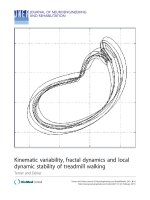
Because high preferential growth happens under high
reaction temperature, the field emission tests for those
Ag-TCNQ nanowires grown under 413 K with 10, 30 and
50-nm-thick Ag film are shown in Fig. 5a, b, respec-
tively. It is shown that the turn-on field is 11.5, 9.3 and
13.5 V/lm, respectively, with the increasing of thickness.
Since the samples are grown under the same temperature,
the crystal structure is the same phase I. The difference in
field emission mainly depends on the morphology of nano-
wires array. From the corresponding SEM images in Fig. 2
maybe some defects exist on the side of the nanowires in
Fig. 2a. No enough tips are contributed to the field emission.
While too many nanowires align parallel in Fig. 2c, the field
enhancement factor is smaller resulting from the reduced
local field on the tips, due to the screening effect. So we can
conclude that both the morphology and proper density of
Fig. 2 SEM top-view images of Ag-TCNQ nanowires, with 10, 30 and 50-nm-thick Ag film at 413 K, respectively
5 10152025303540
+phase I
phase I
phase II
Intensity(a.u.)
2 Theta (de
g
)
90
°
C
100
°
C
150
°
C
120
°
C
Fig. 3 XRD patterns of Ag-TCNQ nanostructures on Si, substrate
under different temperatures, respectively
0123456789
-10
0
10
20
30
40
50
60
phase I
phase II
+phase I
30 nm Ag film
Curent Density (µ
A/cm
2
)
Applied field (V/µm)
100
°
C
120
°
C
140
°
C
Fig. 4 J–E curves of field emission for Ag-TCNQ nanowires, grown
at different temperature
Nanoscale Res Lett (2010) 5:1307–1312 1309
123
nanowires are contributed to the lowest turn-on field for the
samples in Fig. 2b.
In order to analyze the origin of field emission from
nanostructures, the revised Fowler–Nordheim(F–N) model
is often used. If the plot of (ln (J/E
2
) vs. 1/Eorln (I/V
2
) vs.
1/V) yields a straight line, it implies that a quantum tun-
neling process is responsible for the field emission. The
slope of the F–N plot can be expressed as [10]:
slope ¼À
BU
3=2
b
ð1Þ
or
slope ¼À
BU
3=2
d
b
ð2Þ
where B is the constant of 6.83 9 10
3
, d is the vacuum gap
distance between electrodes. Three F–N plots of Ag-TCNQ
nanowires grown with different thickness of Ag film are
given in Fig. 5a corresponding to the J-E curves in Fig. 5b.
In the middle curve for sample with the 10-nm-thick Ag
film, the nonlinearity is obvious; but both of the others
show a good line with almost the same slope. The fol-
lowing are the reasons for the nonlinearity. First, from the
corresponding SEM images in Fig. 2a, there are many
nanowires lying on the substrate. The side of Ag-TCNQ
nanowire acts as emitters, some defects (adsorbates) on the
side may first emit the electrons. Its field enhancement
factor is different from the tip of nanowires in the other two
samples. Second, different enhancement factors appear in
different field regions. In the low field region, these defects
have larger enhancement factor, resulting in a lower slope.
With the increase in the field, the defects become less and
at the same time some nanowires with smaller factor than
that of those defects contribute to the emission current. As
a result, higher slope appears in this field region. With the
field further increasing, smaller slope results from both
lying and vertical wires with little defects. Semet [11]
reported that the linearity of F–N plot can be obtained by
desorbing by applying the field for long time. It can be
reduced that the defects (adsorbate) in the body of emitters
result in the emission current and then the nonlinear F–N
plot. Other nonlinearity in nanomaterials is reported either
and discussed [12, 13].
Allowing for the switching effect for single M-TCNQ
nanowires at the order of V/lm[13], identical to the
applied field for emission, it is necessary to consider the
effect during the field emission process. To study the
process of field emission for Ag-TCNQ nanostructured
arrays, XRD analysis was used to characterize the crystal
structure of the samples after the field emission test. It is
shown in Fig. 6a. From comparison with the patterns for
samples as-grown in Fig. 1, this sample after emission at
the high field regions gives XRD peaks locating at 2theta
equal to 38.52 and 44.60 indexing for Ag(111) and
(200), i.e., showing the same switching effect from single
Ag-TCNQ nanowire. After the applied field reaches the
value of turn-on field, the switching happens, and as a
result the lower resistivity of the nanostructured array
shows good field emission property with higher current
density.
Figure 6b, c shows the I-E curves and corresponding
F–N plots for sweeping emission from Ag-TCNQ nano-
wires with 30-nm-thick Ag film. The I-E curves in Fig. 6b
almost remain coincident, but the corresponding F–N plots
for them are not in complete agreement especially in low
field region shown in Fig. 6c. These F–N plots are sepa-
rated with low and high field regions for each sweeping
process. The intercedes of the F–N plots in y-axis are
equal, suggesting that the emission area in this high field
region not changed, and the stability of field emission is
high. The slopes and intercedes of these plots in the high
field region are the same, showing the effective emission
area and the emission for the Ag-TCNQ nanowires con-
stant and stable.
6 7 8 9 10 11 12 13 14 15 16 17
0
10
20
30
40
50
60
70
80
Applied field (V/µm)
Curent Density (
µ
A/cm
2
)
50nm
30nm
10nm
d=600 m
140
°
C
0.00010 0.00015 0.00020 0.00025 0.00030
-21
-20
-19
-18
-17
-16
-15
-14
-13
k=61459,
beta=150 or 120
k=96442,
beta=100
ln(I/V
2
) ( AV
-2
)
1/V (V
-1
)
50nm
30nm
10nm
Linear Fit of Data1_30nm
Linear Fit of Data1_50nm
(a)
(b)
°
Fig. 5 a J–E curves of field emission for Ag-TCNQ nanowires
grown with 10, 30 and 50-nm-thick Ag film, the gap distance between
electrodes d is 600 lm, b Field emission corresponding F–N curves
for Ag-TCNQ nanowires, with different Ag film thickness
1310 Nanoscale Res Lett (2010) 5:1307–1312
123
Those different nanostructures array with some certain
morphology have different field enhancement factor and
effective work function. From the Eq. 2, we can estimate
the work function by supposing properly a given field
enhancement factor and evaluating the slope of the F–N
plots in Fig. 6c. For those grown with 30-nm-thick Ag
films in Fig. 2, the length maximum of nanowires is sup-
posed to be about 10 lm, and the diameter is about 100 nm
combined with SEM images.
Allowing for the electrical switching effect, the first
decreasing the field is the process of recovery of Ag-TCNQ
with high competence. If the field enhancement factor
being 150 and 120 for Ag-TCNQ nanowires, respectively,
the local effective work function for Ag-TCNQ nanowires
in form of phase I can be derived to be 1.71 and 1.48 eV,
respectively according to the slope of plot 3 in Fig. 6c. The
work function for Ag-TCNQ nanowires grown with the
initial 50-nm-thick Ag film is derived similarly to be
1.77 eV with the value of field enhancement factor being
100 in Fig. 5b. So the work function for the Ag-TCNQ
nanowires array is smaller than 1.77 eV.
Properties comparison of field emission from other
organic materials is listed in the Table 1 for comparison.
Although the turn-on field is higher in our tests, but the
lower work function shows the potential application in
Organic FEDs. The lower temperature will produce the Ag-
TCNQ phase II with lower turn-on field. And the main
point for good field emission lies on the high conductivity
and the regular array density. Further work needs to be
done to verify the difference between two phases and to
improve the field emission property of Ag-TCNQ. Perhaps,
copper tetra-cyanoquinodimethane(Cu-TCNQ) nanowires
are worth to be studied because much higher conductivity
in bulk materials exists [14]. Moreover, recent work on the
single Cu-TCNQ nanowire shows that the threshold field
for the switching effect is about 1.2 V/lm[5], which
is lower than that of single Ag-TCNQ nanowire being
9.3 V/lm[15].
5 101520253035404550
Ag-TCNQ on Si (111)
after field emission
Intensity (a.u.)
2 Theta (deg)
28.43
Si(111)
38.52 Ag(110)
44.60
Ag(200)
27.27
32.09
35.40
14.94
6789101112
-5
0
5
10
15
20
25
30
35
40
Emission Current (
µ
A)
Applied field (V/ m)
1 in
2 in
3 de
4 in
30nmAg 140
°
C
d=600
m
0.00015 0.00018 0.00021 0.00024 0.00027 0.00030
-21
-20
-19
-18
-17
-16
-15
-14
-13
ln(I/V
2
) (
AV
-2
)
1/V (V
-1
)
30 nm Ag, 140
°
C
d=600
µm
1
2
3
4
(a)
(b) (c)
Fig. 6 a XRD patterns for Ag-
TCNQ nanowires after field
emission, b I-E curves of field
emission for Ag-TCNQ
nanowires by sweeping field
tests, c F–N curves for Ag-
TCNQ nanowires corresponding
to b
Nanoscale Res Lett (2010) 5:1307–1312 1311
123
Conclusions
In conclusion, the field emission properties for Ag-TCNQ
nanostructured array were dependent on the structure and
morphology determined by the reaction temperature and
the initial Ag film thickness. The turn-on field to generate a
density of 10 lA/cm
2
increases with the growth tempera-
ture from 373 to 413 K, and the lowest turn-on field
obtained is about 2.0 V/lm for phase II. The deviation
from the F–N linear relation may result from the difference
of field enhancement factors at high and low field region,
not excluding the emission from the surface defects in the
nanowires in the low field region. The effective work
function of Ag-TCNQ phase I nanowires array is estimated
to be about 1.77 eV at most, which is lower among the
organic materials.
Acknowledgment This work is supported financially both by NSFC
(60471010, 60976050) and Postdoctoral Science Foundation of
Jiangsu (0901082C).
Open Access This article is distributed under the terms of the
Creative Commons Attribution Noncommercial License which per-
mits any noncommercial use, distribution, and reproduction in any
medium, provided the original author(s) and source are credited.
References
1. X. Fang, Y. Bando, U.K. Gautam, C. Ye, D. Golberg, J. Mater.
Chem. 18, 509 (2008)
2. J.J. Chiu, C.C. Kei, T.P. Perng, W.S. Wang, Adv. Mater. 15, 1361
(2003)
3. W.Y. Tong, Z.X. Li, A.B. Djurisic, W.K. Chan, S.F. Yu, Mater.
Lett. 61, 3842 (2007)
4. C. Ouyang, Y. Guo, H. Liu, Y. Zhao, G. Li, Y. Li, Y. Song, Y. Li,
J. Phys. Chem. C. 113, 7044 (2009)
5. K.B. Zheng, H.T. Shen, C.N. Ye, J.L. Li, D.L. Sun, G.R. Chen,
Nano-Micro. Lett. 1, 23–26 (2009)
6. H. Liu, Q. Zhao, Y. Li, Y. Liu, F. Lu, J. Zhuang, S. Wang,
L. Jiang, D. Zhu, D. Yu, J. Am. Chem. Soc. 127, 1120 (2005)
7. K. Zheng, X. Li, X. Mo, G. Chen, Z. Wang, G. Chen, Appl. Surf.
Sci. 256, 2764 (2010)
8. Y. Chun-Nuan, C. Guan-Ying, M. Xiao-Liang, F. Fang, X. Xiao-
Yan, C. Guo-Rong, S. Da-Lin, Chin. Phys. Lett. 21, 1787 (2004)
9. S.A. O’Kane, R. Cle
´
rac, H. Zhao, X. Ouyang, J.R. Gala
´
n-Mas-
caro
´
s, R. Heintz, K.R. Dunbar, J. Solid. State. Chem. 152, 159
(2000)
10. R.G. Forbes, K.L. Jensen, Ultramicroscopy 89(1–3), 17 (2001)
11. V. Semet, V.T. Binh, P. Vincent, D. Guillot, K. Teo, M. Chho-
walla, G. Amaratunga, W.I. Milne, P. Legagneux, D. Pribat,
Appl. Phys. Lett. 81, 343 (2002)
12. Y. Chen, S.Z. Deng, N.S. Xu, J. Chen, X.C. Ma, E.G. Wang,
Mater. Sci. Eng. A 327, 16 (2002)
13. N.S. Xu, J. Chen, S.Z. Deng, Appl. Phys. Lett. 76, 2463 (2000)
14. R.A. Heintz, H. Zhao, X. Ouyang, G. Grandinetti, J. Cowen, K.R.
Dunbar, Inorg. Chem. 38, 144 (1999)
15. Z.Y. Fan, X.L. Mo, G.R. Chen, J.G. Lu, Rev. Adv. Mater. Sci. 5,
72 (2003)
Table 1 Properties comparison of some organic materials for field emission
Materials Vacuum gap (lm) (thickness) Turn-on field (V/lm) Work function (eV) Ref.
Ag-TCNQ 600 (50 nm Ag) 13.5 1.77 Our work
Ag-TCNQ 600 (30 nm Ag) 9.3 1.71 or 1.48 Our work
Ag-TCNQ (foil) 2.58 1.19 Ref. [6]
Cu-TCNQ (foil) 3.13 2.77 Ref. [6]
F16CuPc 9.3,9.8,12.7 5.1 Ref. [3]
CuPc 8.7(alfa) 8.1(beta) 9.7(alfa ? beta) 4.62 Ref. [3]
F4TCNQ-Ag 300 (foil) 5.21 1.07 Ref. [4]
F4TCNQ-Cu 300 (foil) 5.48 2.39 Ref. [4]
AlQ3 10 3 Ref. [2]
1312 Nanoscale Res Lett (2010) 5:1307–1312
123