Báo cáo hóa học: "Research Article Efficient Transmission Schemes for Multiuser MIMO Downlink with Linear Receivers and Partial Channel State Information" potx
Bạn đang xem bản rút gọn của tài liệu. Xem và tải ngay bản đầy đủ của tài liệu tại đây (737.83 KB, 12 trang )
Hindawi Publishing Corporation
EURASIP Journal on Wireless Communications and Networking
Volume 2010, Article ID 572675, 12 pages
doi:10.1155/2010/572675
Research Article
Efficient Transmission Schemes for Multiuser MIMO Downlink
with Linear Receivers and Partial Channel State Information
Mohsen Eslami
1, 2
and Witold A. Krzymie
´
n
1, 2
1
Electrical & Computer Engineering, University of Alberta, Edmonton, Alberta, Canada T6G 2V4
2
TRLabs, Edmonton, Alberta, Canada T5K 2M5
Correspondence should be addressed to Witold A. Krzymie
´
n,
Received 18 August 2009; Accepted 10 May 2010
Academic Editor: Alex B. Gershman
Copyright © 2010 M. Eslami and W. A. Krzymie
´
n. This is an open access article distributed under the Creative Commons
Attribution License, which permits unrestricted use, distribution, and reproduction in any medium, provided the original work is
properly cited.
Downlink of a multiuser MIMO system is considered, in which the base station (BS) and the user terminals are both equipped with
multiple antennas. Efficient transmission schemes based on zero-forcing (ZF) linear receiver processing, eigenmode transmission,
and partial channel state information (CSI) at the BS transmitter are proposed. The proposed schemes utilize a handshaking
procedure between the BS and the users to select (schedule) a subset of users and determine the precoding matrix at the BS. The
advantage of the proposed limited feedback schemes lies in enabling relatively low-complexity user scheduling algorithms and high
sum-rate throughput, even for a small pool of users. For large user pools and when the number of antennas at each user terminal
is at least equal to the number of antennas at the BS, we show that the proposed scheme is asymptotically optimum.
1. Introduction
Increasing demand for broadband wireless services calls for
much higher throughputs in future wireless communication
systems. It has been shown that with the use of multiple
antennas at the transmitter (Tx) and the receiver (Rx), the
capacity of a point-to-point communication link increases
linearly with min
{M, N} where M is the number of Tx
antennas and N is the number of Rx antennas [1, 2].
Recently, there has been a great interest in multiuser
multiple-input multiple-output (MU-MIMO) systems and
transmission strategies that would enable similar capacity
gains in multiuser environment [3–5]. In a multiuser down-
link with the base station (BS) equipped with multiple anten-
nas, multiple users can be served simultaneously. In fact, it
has been shown that to obtain the MU-MIMO downlink
sum capacity, transmitting to several users simultaneously
must be considered [6]. Since the number of users in the
system is usually greater than the maximum number that can
be served simultaneously through spatial multiplexing, user
selection is required. User selection (or scheduling) favours
users, which experience better propagation condition while
being sufficiently separated in space. Such user scheduling
leads to multiuser diversity gain [7, 8], which increases with
increasing number of users awaiting transmission.
It has been shown that the capacity of the MU-MIMO
downlink can be achieved by dirty paper coding (DPC) [6],
which is a transmitter multiuser encoding strategy based on
interference presubtraction. DPC requires nonlinear search
for optimal precoding matrices as well as noncausal channel
coding for these users, which is practically impossible in real-
time systems. Therefore, suboptimum transmission strate-
gies such as different forms of beamforming have been con-
sidered in the literature. In MU-MIMO beamforming, linear
or nonlinear transmitter precoding algorithms together with
user scheduling are designed to maximize the system’s
sumrateorsomeotherrelatedobjectivefunction(e.g.,
sum rate under fairness constraint). Unfortunately, most
beamforming algorithms considered assume availability of
perfect channel state information at the transmitter, which
presents a big challenge to their practical implementation
(references [9, 10] and references therein contain an overview
of the subject).
To overcome this challenge, suboptimal MU-MIMO
downlink transmission based on partial channel state infor-
mation (CSI) has been studied in the literature. Some of
2 EURASIP Journal on Wireless Communications and Networking
the proposed approaches can be applied to systems with
only single antenna user terminals [11–16], while some
accommodate multiple antenna user terminals [17–23].
When multiple antenna user terminals are considered, often
it is assumed that all user terminals have the same number
of antennas. This might not be true in practice. However,
schemes which rely on this assumption may use antenna
selection to meet the requirement. Most of the existing MU-
MIMO downlink schemes using partial CSI fall under three
main categories.
(1) Transmission schemes based on availability of quan-
tized channel state information at the BS: the quan-
tized CSI is used to utilize a variant of beamforming
at the BS. See [12] and references therein for further
details.
(2) User scheduling and precoder selection from a codebook
of vectors/matrices known a priori to both the BS and
the users based on partial CSI : the scheme proposed
in [17] called transmit beam matching (TBM) is
one example, which extends the per-user unitary
rate control (PU
2
RC) [12, 24] approach to multi-
ple antenna users. PU
2
RC is Samsung Electronic’s
proposal to the 3rd Generation Partnership Project
(3GPP). The proposed approach is characterized by
the relatively low complexity structure of PU
2
RC,
and it uses channel matrix pseudoinverse operation
in order to minimize interstream interference at
each user’s terminal. However, when users have
fewer antennas than the base station, the pseu-
doinverse operation can not completely eliminate
interstream interference, which leads to some per-
formance degradation. A similar approach called
random precoding has been introduced in [19].
(3) Eigenmode transmission with limited feedback:One
example is [20], which employs singular value
decomposition (SVD) of user channel matrices and
data transmission on the eigenmode with the largest
gain. Another example is [25], in which the authors
propose a combination of zero-forcing beamforming
(ZF-BF) with eigenmode transmission.
All schemes mentioned above use precoding at the BS. In
addition to precoding at the BS, multiple antenna users can
use their antennas to process their received signal vector
using relatively low-complexity linear schemes such as zero-
forcing (ZF) and minimum mean squared error (MMSE)
processingandsendbacksomesortofchannelquality
indicator (CQI), for example, SINR or rate, to the BS. One
example is [21], in which a MIMO downlink scheme with
opportunistic feedback is proposed. In this scheme users
use ZF linear processors and send back the quality indicator
for each spatial channel to the base station according to an
opportunistic feedback protocol. The main contribution of
[21] lies in its feedback protocol and not the transmission
scheme itself.
In this paper, we present a transmission scheme for
MU-MIMO downlink using eigenmode transmission, and
ZF linear processing, which only requires partial CSI and
falls under the third category mentioned above. We assume
that all users have the same number of Rx antennas. With
this assumption and the number of Rx antennas of each
user terminal being less or greater than the number of
transmit antennas, two transmission strategies are proposed.
For systems where the number of Rx antennas is greater
than or equal to the number of Tx antennas, one user is
selected to receive data through eigenmode transmission and
its right eigenvector matrix is used for precoding, while other
selected users use ZF linear processing. When the number of
Rx antennas of each user terminal is less than the number of
Tx antennas at the base station, partial CSI at the base station
is used to design a precoding matrix such that the number
of interfering streams at the selected user terminals (after Rx
preprocessing) is reduced to the number of Rx antennas, and
ZF receiver processing can be efficiently applied. Analytical
expressions and approximations are derived for the sum
rate of the proposed scheme and also for time division
multiplexing (TDM) with eigenmode transmission.
For the case of N
≥ M (N denotes the number of Rx
antennasateachuserterminal;M denotes the number of
Tx antennas at the BS), our work is distinct from [20]in
the following aspects. (1) In our proposed scheme the users
do not need to send back their channel singular vectors as
required in the scheme of [20]; only one user is asked to
send back its right singular vector matrix. (2) The scheme
presented here results in zero interuser and interstream
interferences, whereas the scheme of [20] does not. (3) In
our scheme user selection criterion is straightforward and
there is no need for a greedy search algorithm to select users
as required by the scheme introduced in [20]. Compared to
[25], what distinguishes our work is the use of ZF receiver
processing and the lower complexity of our user scheduling
and eigenmode assignment to selected users compared to the
high complexity of exhaustive search to find the threshold
value (denoted by t in [25]).Partsofthisworkhavebeen
presented in [26, 27]. Nevertheless, this paper generalizes our
proposed scheme to any number (greater than one) of Tx (at
the BS) and Rx (at each user terminal) antennas and provides
further analysis on the proposed scheme’s sum rate.
The paper is organized as follows. In Section 2, the system
model for multiuser MIMO downlink is described. Two
well-known transmission schemes based on limited feedback
are briefly outlined in Sections 3 and 4. Section 5 describes
the proposed transmission techniques along with asymptotic
analysis for the case of N
≥ M. Numerical results are
provided in Section 6,andSection 7 concludes the paper.
Throughout this paper, upper case and lower case bold
characters denote matrices and vectors, respectively. (
·)
H
denotes the conjugate transpose of the matrix argument.
E
{·} is the expectation operation. Tr(·) denotes the trace of
the matrix argument.
2. System Model
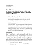
Figure 1 shows the block diagram of a MU-MIMO downlink.
Consider a Gaussian MIMO broadcast channel where the
base station is equipped with M antennas, and there are
K homogeneous users each equipped with N antennas.
EURASIP Journal on Wireless Communications and Networking 3
User 1 data
User K data
Scheduling
and
Tx
processing
1
M
1
N
User 1
Rx
User K
Rx
1
N
Feedback channel
Feedback channel
Figure 1: Block diagram of an MU-MIMO downlink.
A quasistatic Rayleigh flat fading model is assumed for
the channel where the channel gains do not change within
a frame and change independently from frame to frame
following complex Gaussian distribution. The kth user
receives the following signal vector:
y
k
= H
k
x + n
k
,
(1)
where H
k
∈ C
N×M
is the downlink channel gain matrix
between the base station and the kth user, and n
k
∈ C
N×1
is the noise vector. Both H
k
sandn
k
sareassumedto
have independently and identically distributed (i.i.d.) zero
mean unit variance complex Gaussian elements, CN (0, 1).
The vector x is the transmitted signal vector such that
Tr(E[xx
H
]) = P
T
. Hence, the average signal-to-noise ratio
(SNR) equals P
T
, which also defines the average power
constraint of the base station. The data symbol vector s is
asizeM
× 1 vector. When precoding is used, the precoding
matrix is denoted by Ψ where x
= Ψs, and in case of spatial
multiplexing Ψ
= I
M×M
. Let the total (sum) rate delivered by
the base station to the users during one time slot be R. Then
the expected throughput of the system is obtained by taking
ensemble average of R over H
k
s, that is, R
Ave
= E
H
1
, ,H
K
{R}.
Throughout the paper, the terms system throughput and
sum rate are used interchangeably.
3. Eigenmode Transmission
Consider the singular value decomposition (SVD) of the kth
user’s channel gain matrix
H
k
= U
k
Σ
k
V
H
k
(2)
where U
k
= [u
(k)
1
··· u
(k)
N
]andV
k
= [v
(k)
1
··· v
(k)
M
]are
N
× N left singular vector and M × M right singular vector
unitary matrices, respectively. The matrix Σ
k
is an N × M
diagonal matrix with nonnegative numbers (singular values)
on its diagonal. Consider data transmission to only one user
at any given time. When the transmitter has the knowledge
of H
k
, it precodes the transmitted signal by V
k
, while the kth
receiver uses U
H
k
as its receive processing matrix. Therefore,
the channel is diagonalized into parallel interference-free
channels, also called eigenchannels [28], where the gain of
each channel equals its corresponding singular value. In this
case, the rate delivered to user k (in bits/s/Hz) is obtained as
R
k
=
M
m=1
log
2
1+ρ
m
λ
(k)
m
,
(3)
where λ
(k)
m
= σ
(k)
2
m
is the mth eigenvalue of H
H
k
H
k
while σ
(k)
m
is
the mth singular value of H
k
. ρ
m
denotes the power given to
the mth data stream and
M
m
=1
ρ
m
= P
T
.Theoptimumpower
distribution over the spatial channels is obtained through
water-filling [28]. For the case of equal power allocation
we have ρ
m
= P
T
/M. This transmission scheme has been
considered within the context of time-division multiplexing
(TDM) where the users send back their achievable rate,
R
k
, to the base station and the base station selects the
user with the largest achievable transmission rate in each
time slot. Compared to multiuser MIMO schemes in which
multiple users are served simultaneously, this scheme is very
suboptimal as it does not take full advantage of multiuser
diversity, which implies that some of the eigenmodes of the
selected user’s channel matrix might be very weak.
4. Zero-Forcing Receiver Processing and
Scheduling based on Partial Side Information
In case of N ≥ M, with spatial multiplexing at the base
station when an independent data stream is transmitted
from each Tx antenna and ZF receiver processing is used at
each user terminal, the scheduled users can detect their data
without interstream interference.
ZF receiver processing at the kth user is applied by
multiplying the received signal by
G
k
=
H
H
k
H
k
−1
H
H
k
.
(4)
The postprocessing SNR of the mth data stream at user k is
then given as [29]
γ
(k)
m
=
ρ
H
H
k
H
k
−1
mm
.
(5)
where ρ
= P
T
/M and [A]
mm
denotes the mth diagonal
term of the matrix A. Once the base station is informed of
postprocessing SNR of a specific data stream by all users,
it will assign that data stream to the user with the highest
postprocessing SNR. Therefore, the sum rate (in bits/s/Hz)
will be given by
R
ZF
=
M
m=1
log
2
1+γ
(
k
m
)
m
,
(6)
4 EURASIP Journal on Wireless Communications and Networking
where
k
m
= argmax
k
γ
(k)
m
. While this scheme is asymptotically
optimal [30], that is,
lim
K →∞
E{R
ZF
}
E{R
DPC
}
=
1,
(7)
where R
DPC
is the sum rate of the DPC scheme, for a small
pool of users it achieves a relatively poor sum rate.
5. The proposed Transmission Scheme:
Eigenmode Transmission with Zero-Forcing
Receiver Processing
In the next subsections our proposed transmission scheme is
presented for two scenarios. In the first scenario, each user
terminal has the number of antennas at least equal to that of
the base station (M
≤ N), and in the second scenario the base
station has more antennas than each user terminal (M>N).
5.1. Case N
≥ M: Precoding with Right Singular Vector
Matrix. The proposed scheme is presented in an algorithmic
form as follows.
(1) All the users perform SVD of their own channel and
report back a single rate value evaluated according to
r
k,L
=
L
i=1
log
2
1+ρλ
(k)
i
,
(8)
where ρ
= P
T
/M. The parameter L is evaluated
beforehand based on the system parameters and will
be discussed in the next subsection. λ
(k)
i
s are the
ordered eigenvalues of the matrix W
k
= H
H
k
H
k
which
is a complex Wishart matrix [31]. λ
(k)
1
is the largest
eigenvalue.
(2) The base station scheduler selects the user with the
largest r
k,L
(user k
s
) and asks that user to send its V
k
s
matrix to the BS. The matrix V
k
s
is obtained through
the SVD of the selected users’ channel matrix. The
matrix V
k
s
is then used as the precoding matrix,
Ψ
= V
k
s
. User k
s
will receive its data through
the first L(L<M) data streams (encompassing
data symbols s
1
, s
2
, , s
L
), using U
H
k
s
as its receiver
processing matrix (eigenmode transmission).
(3) User u (u
/
= k
s
) will estimate its equivalent channel,
which at this stage is
H
u
= H
u
V
k
s
. Then all users
(except user k
s
) will apply ZF linear processing using
the estimated equivalent channel and send back the
postprocessing SNR of data streams L +1toM to the
base station.
(4) For each of the remaining M
− L data streams,
the base station selects the user with the highest
postprocessing SNR.
5.1.1. Finding the Optimum Number of Eigenmodes (L). Since
the precoding matrix, Ψ, in this case is a unitary matrix,
the statistics of the equivalent channel
H
k
= H
k
Ψ do not
change. Assuming that the first L data symbols have been
assigned to user k
s
and the remaining M − L to users with
ZF receivers, which have the highest postprocessing SNR, the
average sum rate is obtained by taking the ensemble average
of the rate contribution from eigenmode transmission on the
first L eigenmodes, R
eig
(L), and the rate contribution from
the remaining M
− L data streams using linear ZF receiver
processing, R
ZF
(M − L), over a large number of channel
realizations:
R
Ave
= E
R
eig
(
L
)
+ E{R
ZF
(
M
− L
)
}
=
E
⎧
⎨
⎩
L
l=1
log
2
1+ρλ
(k
s
)
l
⎫
⎬
⎭
+ E
⎧
⎨
⎩
M
m=L+1
log
2
1+ρξ
m,v
∗
⎫
⎬
⎭
,
(9)
where ξ
m,v
∗
= 1/[(
H
H
v
∗
m
H
v
∗
m
)
−1
]
mm
,and[·]
mm
denotes the mth
diagonal term of its matrix argument. The user v
∗
m
is the user
which has the largest postprocessing SNR for the mth data
stream among K
− 1 users (user k
s
has been subtracted out
from the set
{1, , K}), that is,
v
∗
m
= arg max
k,k
/
= k
s
ξ
m,k
, L<m≤ M.
(10)
The probability density function (pdf) of ξ
m,v
∗
m
for a square
system M
= N is obtained using order statistics and is given
by [29]
f
ξ
m,v
∗
m
(
x
)
=
(
K
− 1
)(
1 − e
−x
)
K−2
e
−x
,
L<m
≤ M, x ≥ 0
(11)
which is independent of data stream’s index, m.Fora
nonsquare system (N>M), the exponential functions in
(11) are replaced with chi-square distribution functions with
2(N
− M + 1) degrees of freedom [29]. Using (11), the
expected throughput contribution from ZF Rx processing is
obtained as
E
{R
ZF
(
M
− L
)
}=
(
M
− L
)
∞
0
log
2
1+ρx
f
ξ
m,v
∗
m
(
x
)
dx
(12)
which for the case of M
= N is further simplified to [29]
E
{R
ZF
(
M
− L
)
}
=
(
M
− L
)(
K − 1
)
ln
(
2
)
×
K−2
q=0
1
q +1
K − 2
q
(
−1
)
q
exp
q +1
ρ
E
1
q +1
ρ
(13)
EURASIP Journal on Wireless Communications and Networking 5
where E
1
(·) is the exponential integral function [32]. To
obtain the expected throughput of the eigenmode transmis-
sion, the pdf of ordered eigenvalues of W
k
is required. The
joint pdf of the ordered eigenvalues is given by [33]
p
λ
(
λ
1
, , λ
M
)
= K
c
e
−
M
i
=1
λ
i
M
i=1
λ
N−M
i
1≤i<j≤M
λ
i
− λ
j
2
,
(14)
where K
−1
c
=
M
i=1
Γ(M − i +1)Γ(N − i + 1) is the product of
2M Gamma functions.
For L>1, a closed form analytical expression for the
average throughput contribution from eigenmode transmis-
sion, E
{R
eig
(L)}, is very complicated to evaluate. However, a
close approximation for E
{R
eig
(L)} can be obtained using the
following proposition.
Proposition 1. For a Gaussian MIMO broadcast channel with
M transmit antennas and K users each equipped with N
≥ M
receive antennas, a close approximation to the average sum rate
of eigenmode transmission on the first L(
≤ M) eigenmodes is
E
R
eig
(
L
)
≈
σ
r
k,L
0.1975
0.5264
0.135/K
− (1 − 0.5264
1/K
)
0.135
+ μ
r
k,L
,
(15)
where
σ
2
r
k,L
=
L
i=1
L
j=1
E
R
(k)
λ
i
R
(k)
λ
j
−
E
R
(k)
λ
i
E
R
(k)
λ
j
,
μ
r
k,L
=
L
l=1
∞
0
log
2
1+ρx
p
λ
λ
(k)
l
(
x
)
dx,
(16)
and R
(k)
λ
i
= log
2
(1 + ρλ
(k)
i
) is the achievable rate on the ith
eigenmode.
Proof. See the appendix.
In summary, to find the optimum L, one has to find the
smallest eigenvalue, λ
t
,forwhichE{R
eig
(t)} >E{R
ZF
(M −
t)}. Then the optimum value for L is L = t.ToobtainR
eig
(t),
the marginal pdf, CDF, and joint pdfs of λ
(k)
l
,1≤ l ≤ t
are required, which can be obtained using (14). E
{R
eig
(t)}
is then approximated using (15). Based on (12)and(15),
the optimum L value depends on M, N, ρ and K.Fora
system with specific number of Tx and Rx antennas, L can
be evaluated for different values of ρ and K beforehand and
stored in a lookup table to be used later.
5.1.2. Scaling Law of Sum Rate of the Proposed Scheme. In this
subsection, the asymptotic behaviour of the average sum rate
of the proposed scheme described in 5.1 is investigated for
systems with a large number of users. First we start with the
following lemma,
Lemma 1. For fixed M, N,andρ one has,
lim
K →∞
E
R
eig
(
L
)
L ln
[
ln
(
K
)
]
≤ 1,
(17)
where ln(
·) is the natural logarithm.
Proof. An upper bound for r
k,L
is
r
k,L
=
L
l=1
log
2
1+ρλ
(k)
l
≤
L log
2
1+ρλ
(k)
1
≤
L log
2
⎛
⎝
1+ρ
M
m=1
λ
(k)
m
⎞
⎠
=
L log
2
1+ρ Tr
(
W
k
)
.
(18)
Using the definition of the trace of a matrix,
Tr
(
W
k
)
= Tr
H
H
k
H
k
=
N
n=1
M
m=1
h
(k)
n,m
2
(19)
which is a chi-square random variable with 2MN degrees of
freedom. Since R
eig
(L) = arg max
1≤k≤K
r
k,L
, according to [30,
34]wehave
lim
K →∞
E
R
eig
(
L
)
L ln
[
ln
(
K
)
]
≤ lim
K →∞
log
2
1+ρ Tr
(
W
k
)
ln
[
ln
(
K
)
]
= 1, (20)
and that completes the proof.
As the sum capacity (achievable with DPC) for L data
streams asymptotically increases with L ln[ln(LK)] [35],
R
eig
(L), in general is not asymptotically optimum. However,
for the case of L
= 1 we present the following theorem.
Theorem 1. TheproposedschemewithL
= 1 is asymptotically
optimal
lim
K →∞
R
Ave
E{R
DPC
}
=
1.
(21)
Proof. For L = 1wehave
R
Ave
= E
R
eig(1)
+
(
M − 1
)
E{R
ZF
(
M
− 1
)
}. (22)
When K is very large, referring to Lemma 1, and according
to [36]
E
{R
DPC
}≤ME
log
2
1+ρλ
1,max
=
ME
R
eig
(
1
)
,
(23)
where λ
1,max
= max
k=1, ,K
λ
(k)
1
. Also [30]
lim
K →∞
E{R
ZF
(
M
− 1
)
}
E{R
DPC
}
=
1
M
.
(24)
6 EURASIP Journal on Wireless Communications and Networking
Considering (23)and(24),
lim
K →∞
R
Ave
E{R
DPC
}
≥
1
M
+
M
− 1
M
= 1
(25)
and since DPC has the optimum scaling sum rate, the ratio
in the above equation can not be greater than one.
The above lemma and theorem make one expect that
as the number of users increases, the optimum L value
will decrease to one, which is confirmed by simulations in
Section 6.
5.2. Case M>N: Null Space Precoding with Singular Vector
Selection. In this section, the general algorithm proposed for
this case is presented, before a novel scheme for the specific
case of M
= 3TxandN = 2 Rx antennas is discussed.
Assume the precoding matrix to consist of M vectors each
selected from the right singular vector matrix of a selected
user (there is a possibility that one user contributes more
than one vector) given in general form by
Ψ
=
v
(k
1
)
p
1
··· v
(k
M
)
p
M
. (26)
where k
i
∈{1, , K} and p
i
∈{1, , M}. The signal vector
at the kth user, k
∈{k
1
, , k
M
},aftereigenmodeRxpre-
processing (multiplying the received signal vector by U
(k)
H
)
is
z
k
= Σ
k
V
H
k
Ψ
Δ
k
x + n
k
.
(27)
Considering the fact that the last M
−N columns of Σ
k
are all
zero columns, and also for i
/
= j, v
(i)
H
k
v
(j)
k
= 0, it can be shown
that when Ψ contains M
− N rightmost vectors of V
k
, then
the nonzero terms of Δ
k
form the following submatrix:
Δ
k
=
Σ
k
V
H
k
Ψ
,
(28)
where
Δ
k
is an N ×N matrix,
Σ
k
is an N ×N square diagonal
matrix with N singular values on its diagonal,
V
k
contains
only the first N columns of V
k
,and
Ψ contains N vectors
that belong to V
k
i
swherek
i
∈{k
1
, , k
M
} and k
i
/
= k. In this
case, (27)canberewrittenas
z =
Δ
k
x + n
k
,
(29)
where
x is a size N vector and is obtained by eliminating M −
N terms from x. Then user k uses G
k
=
Δ
−1
k
as its receiver
processing matrix to detect N out of the total M transmitted
data streams.
For the kth receiver to be able to detect its data using ZF
receiver processing, the number of interfering data streams
(after Rx pre-processing) must not be greater than N.In
other words, the matrix Δ
k
must have M − N zero columns.
This further implies that the precoding matrix needs to
contain M
− N basis vectors of the null space (space spanned
by the rightmost M
− N vectors of V
k
) of each selected
user’s channel matrix. Therefore,
M/(M − N) users can
be served simultaneously (
· denotes floor of its argument).
Therefore, to be able to take greater advantage of multiuser
diversity, N should be as close as possible to M with the best
case being N
= M − 1. When N<M/2thisschemebecomes
identical to TDM.
Since the postprocessing SNR of each data stream
in this case depends on the precoding matrix and each
selected user’s Σ and V matrices, finding users with channel
conditions that maximize the sum rate based on partial CSI
turns out to be not straightforward. Nevertheless, a heuristic
approach would be to adopt a two-stage user selection, where
in the first stage a set of users is selected based on a channel
quality indicator (CQI), for example, the largest singular
value. In the next stage, the selected users send back their
full CSI to the BS, and the BS broadcasts their CSI to all
users. Then, knowing the CSI of the selected users, each
user (outside of the set of selected users) substitutes itself
sequentially for each of the selected users and evaluates the
resulting sum rate for each substitution. If a user finds that
by substituting itself for one of the selected users, the sum
rate increases, it will inform the BS of it. The BS will update
the user set according to the suggestion of the user which has
reported the maximum increase in the sum rate. Our results
show that the sum rate obtained by adopting this scheme and
user selection based on the largest eigenvalue achieve a higher
sum rate compared to TDM, while the gap between the sum
rate of this scheme and the optimum DPC increases as the
number of antennas increases. In the following subsection
we present an efficient transmission scheme for the special
case of M
= 3andN = 2.
The Case of M
= 3 and N = 2. Considering the general
idea discussed for null space precoding based on eigenvector
selection, in this case we consider two possibilities for the
precoding matrix. One possibility is to construct Ψ using
three vectors each taken from right singular vector matrix
of a distinct user’s channel matrix. Therefore, three users
can be served and each user sees only one interfering data
stream. However, in order to find the best set of users
which maximizes the sum rate, either the base station
requires full channel state information of all users which
results in a considerably increased complexity compared to
limited feedback schemes, or an approach similar to the one
discussed in the previous section can be applied. The second
option is to construct Ψ using right singular vectors of two
selected user channel matrices. Assume that users k
s
and k
p
where k
s
, k
p
∈{1, , K} are the indexes of users that will
be ultimately scheduled by the proposed algorithm. In the
proposed scheme which is based on a heuristic approach the
precoding matrix is assumed to be
Ψ
=
v
(k
s
)
3
v
(k
p
)
3
v
(k
p
)
2
. (30)
The reasoning behind this choice of precoding matrix will be
clarified once the algorithm is presented. Here are the steps
of the proposed algorithm.
EURASIP Journal on Wireless Communications and Networking 7
(1) Each user performs the SVD of its channel matrix and
sends back σ
(k)
1
to the base station.
(2) The base station selects the user with the largest σ
(k)
1
,
user k
s
, and asks that user for V
k
s
matrix. To detect its
data, user k
s
uses U
H
k
s
as its receiver processing matrix,
z
k
s
= U
H
k
s
y
k
s
= U
H
k
s
U
k
s
Λ
k
s
V
H
k
s
Ψx + U
H
k
s
n
k
s
=
⎡
⎣
0 λ
(k
s
)
1
χ
1
λ
(k
s
)
1
χ
2
0 λ
(k
s
)
2
χ
3
λ
(k
s
)
2
χ
4
⎤
⎦
x + n
k
s
,
(31)
where χ
1
= v
(k
s
)
1
v
(k
p
)
3
, χ
2
= v
(k
s
)
1
v
(k
p
)
2
, χ
3
= v
(k
s
)
2
v
(k
p
)
3
,
and χ
4
= v
(k
s
)
2
v
(k
p
)
2
.Asseenin(31), the interference
caused by the first data stream to the second and third
data streams after Rx processing at user k
s
has been
canceled. Therefore, a ZF linear receiver can be used
and for the second data stream we have [29]
γ
(k
s
)
2
=
ρλ
(k
s
)
1
Ω
H
Ω
−1
11
,
(32)
where Ω
=
χ
1
χ
2
χ
3
χ
4
. Thus, the achievable rate for this
user will be log
2
(1 + γ
(k
s
)
2
).
(3) The base station broadcasts V
k
s
and σ
(k
s
)
1
to all users.
(4) For now, let us assume that user k is the second
selected user. Then the precoding matrix will be
Ψ
=
v
(k
s
)
3
v
(k)
3
v
(k)
2
. (33)
User k once selected uses U
H
k
as its receiver processing
matrix which will result in
z
k
= U
H
k
y
k
= U
H
k
U
k
Σ
k
V
H
k
Ψs
x
+ U
H
k
n
k
=
⎡
⎣
σ
(k)
1
α
k
00
σ
(k)
1
β
k
0 σ
(k)
2
⎤
⎦
⎡
⎢
⎣
s
1
s
2
s
3
⎤
⎥
⎦
+ n
k
,
(34)
where z
k
= [z
(k)
1
z
(k)
2
]
T
, α
k
= v
(k)
H
1
v
(k
s
)
3
,andβ
k
=
v
(k)
H
2
v
(k
s
)
3
. It is evident that the interfering effect of s
2
on the other data streams is canceled, and the first
data stream can be detected using a matched filter,
which results in γ
(k)
1
= ρλ
(k)
1
|α
k
|
2
as postprocessing
SNR for the first data stream (λ
(k)
1
=|σ
(k)
1
|
2
).
To detect the third data stream, the effect of the
first detected data stream is subtracted out, that is,
z
(k)
2
= z
(k)
2
− σ
(k)
1
β
k
s
1
(s
1
denotes the first detected
data symbol). Canceling the effect of the the first data
stream is possible due to the knowledge of v
(k
s
)
3
at user
k which enables it to evaluate β
k
. The SNR for the
third data stream, s
3
, after interference cancelation
and matched filtering, is obtained as γ
(k)
3
= ρλ
(k)
2
(ignoring error propagation).
Considering (32) and the third step of the algorithm,
user k has all the required information to evaluate
the rate of user k
s
as well as its own rate. Therefore,
it will send back a sum rate value, R
k
= log
2
(1 +
γ
(k)
1
) + log
2
(1 + γ
(k)
3
) + log
2
(1 + γ
(k
s
)
2
), that is achieved
by scheduling data transmission to itself and user k
s
.
(5) The base station selects the second user, user k
p
,
which has the largest R
k
and asks that user to send
back v
(k
p
)
2
and v
(k
p
)
3
vectors.
At this stage data transmission to the selected users
begins. User k
p
will receive its data from the first and
third Tx antennas, and user k
s
will receive its data
from the second Tx antenna.
6. Numerical Results
In this section, the expected throughputs of the proposed
schemes are compared to limited feedback MIMO-downlink
techniques using transmit beam matching (TBM) [17],
which is a modified version of PU
2
RC for multiple antenna
users, zero-forcing beamforming (ZF-BF) using channel
vector quantization (CVQ) [18, 37, 38], spatial multiplex-
ing with zero-forcing receiver processing, and TDM with
eigenmode transmission for different numbers of antennas,
users, and SNR values. The throughput of the DPC scheme
is also given as an upper bound on the sum rate. The sum
rate curves for DPC have been obtained using the iterative
water-filling algorithm introduced in [39]. In the following,
we consider two case examples, in which M
= N,andone
example for the case M>N.
TheCaseofM
= 2 and N = 2. In this case, we find
the optimum choice for L in terms of maximizing the
average sum rate. Using (14) it can easily be shown that the
distributions of the ordered eigenvalues, λ
1
and λ
2
,are
p
λ
(
λ
1
)
=
λ
2
1
− 2λ
1
+2
e
−λ
1
− 2e
−2λ
1
, λ
1
≥ 0,
p
λ
(
λ
2
)
= 2e
−2λ
2
, λ
2
≥ 0,
(35)
respectively. The cumulative distribution functions (CDF) of
the eigenvalues are then as followss
F
λ
(
λ
1
)
=
2cosh
(
λ
1
)
− 2 − λ
2
1
e
−λ
1
, λ
1
≥ 0,
F
λ
(
λ
2
)
= 1 − e
−2λ
2
, λ
2
≥ 0.
(36)
To schedule users in this case we consider three possibilities.
(i) The proposed scheme with L
= 1.
8 EURASIP Journal on Wireless Communications and Networking
The average rate for this scheme is obtained as:
R
Ave
= E
R
eig
(
1
)
+ E{R
ZF
(
1
)
},
R
Ave
=
∞
0
K log
2
1+ρλ
1
[
F
λ
(
λ
1
)
]
K−1
p
λ
(
λ
1
)
dλ
1
+
∞
0
log
2
1+ρx
f
ξ
m,v
∗
m
(
x
)
dx.
(37)
(ii) Selecting user k which has the largest r
k,2
(8)and
only serving that user in each time slot (TDM with
eigenmode transmission).
According to Proposition 1, the average sum rate for
this scheme can be approximated by
R
Ave
≈
σ
r
k,2
c
1
c
c
2
/K
3
− (1 − c
1/K
3
)
c
2
+ μ
r
k,2
,
(38)
where σ
r
k,2
and μ
r
k,2
are obtained using (16).
(iii) ZF receiver Rx processing with partial CSI.
Theaveragesumrateforthisschemeisobtainedas
R
Ave
= 2
∞
0
log
2
1+ρx
f
ξ
m,v
∗
m
(
x
)
dx.
(39)
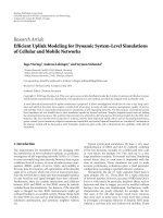
According to Figure 2, the proposed scheme with L
= 1
achieves a considerably higher sum rate compared to ZF
linear processing and TDM. Furthermore, Figure 2 compares
the average sum rate of the proposed scheme with that of
TBM. For the TBM scheme, a codebook size of 4 has been
considered, where each codebook consists of a 2
× 2 unitary
matrix and it is assumed that each user sends back to the
base station 8 SNR values, corresponding to all vectors of
all unitary matrices in the codebook. As the figure shows,
even for a very small user pool, for example, K
= 5
users, the proposed scheme has a great sum rate advantage
over the sum rate of other limited feedback schemes, which
are plotted. Sum rate curves obtained using the analytical
expressions of (37), (38), and (39) are in good agreement
with the simulation results.
The case of M
= 3 and N = 3. We consider four possibilities
for this case.
(i) The proposed scheme with L
= 1.
Theaveragesumrateforthisschemeisobtainedas
R
Ave
= E
R
eig
(
1
)
+ E{R
ZF
(
2
)
},
R
Ave
=
∞
0
Klog
2
1+ρλ
1
[
F
λ
(
λ
1
)
]
K−1
p
λ
(
λ
1
)
dλ
1
+2
∞
0
log
2
1+ρx
f
ξ
m,v
∗
m
(
x
)
dx
(40)
6.5
7
7.5
8
8.5
9
9.5
10
10.5
11
11.5
Average sum rate (bps/Hz)
10
1
10
2
10
3
Number of users (K)
DPC
Proposed scheme, L
= 1
TBM, codebook size
= 4
ZF Rx processing
TDM
Analytical
Figure 2: Sum rate of the proposed scheme compared to a number
of multiuser MIMO techniques for M
= 2TxandN = 2Rx
antennas at 10 dB SNR.
with the pdf and CDF of λ
1
given as follows
p
λ
(
λ
1
)
= 0.25e
−λ
1
12 − 24λ
1
+24λ
2
1
− 8λ
3
1
+ λ
4
1
−
2
12 − 12λ
1
+6λ
2
1
+2λ
3
1
+ λ
4
1
e
−λ
1
+12e
−2λ
1
,
F
λ
(
λ
1
)
= 1 − 0.25e
−λ
1
12 + 12λ
2
1
− 4λ
3
1
+ λ
4
1
−
12 + 12λ
2
1
+4λ
3
1
+ λ
4
1
e
−λ
1
+4e
−2λ
1
, λ
1
≥ 0.
(41)
(ii) The proposed scheme with L
= 2
In this case the average sum rate is obtained as
R
Ave
= E
R
eig
(
2
)
+ E{R
ZF
(
1
)
},
R
Ave
≈ σ
rk,2
Φ
−1
0.5264
1/K
+ μ
r
k,2
+
∞
0
log
2
1+ρx
f
ξ
m,v
∗
m
(
x
)
dx,
(42)
where σ
r
k,2
and μ
r
k,2
are obtained using (16), and
marginal and joint eigenvalue distributions are given
by
EURASIP Journal on Wireless Communications and Networking 9
p
λ
(
λ
2
)
= e
−3λ
2
−
6+0.5e
λ
2
×
12 − 12λ
2
+6λ
2
2
+2λ
3
2
+ λ
4
2
, λ
2
≥ 0,
p
λ
(
λ
3
)
= 3e
−3λ
3
, λ
3
≥ 0,
p
λ
(
λ
1
, λ
2
)
= 0.25
24 − 12λ
1
+2λ
2
1
− 12λ
2
+8λ
1
λ
2
− 2λ
2
1
λ
2
+2λ
2
2
− 2λ
1
λ
2
2
+ λ
2
1
λ
2
2
− 2e
−λ
2
12 − 6λ
1
+ λ
2
1
+6λ
2
− 2λ
1
λ
2
+ λ
2
2
×
(
λ
1
− λ
2
)
2
e
−(λ
1
+λ
2
)
.
(43)
(iii) Selecting user k which achieves the largest rate and
only serving that user in each time slot (TDM with
eigenvalue distribution). The average sum rate in this
case is approximated by (15)withL
= M = 3and
using [40] where more simplified expressions (for
case M
= L)havebeengivenforσ
r
k,3
and μ
r
k,3
.
(iv) ZF receiver processing scheme using partial side
information.
Theaveragesumrateforthisschemeisobtainedas
R
Ave
= 3
∞
0
log
2
1+ρx
f
ξ
m,v
∗
m
(
x
)
dx.
(44)
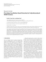
The average sum rates of the four cases considered above
are compared in Figure 3. As seen in the figure, the proposed
scheme with L
= 2 achieves a higher average sum rate
compared to the case of L
= 1 while there are up to K = 12
users in the system. When there are more users in the system,
the proposed scheme with L
= 1achievesahighersumrate.
The intersection of the average sum rate curves for L
= 1
and L
= 2 can be explained by considering the fact that for
asmallpoolofusersitislesslikelythatasubsetofusers
with high ZF postprocessing SNR (good channel conditions)
exist in the system, and therefore transmitting on the first two
noninterfering eigenmodes to one user leads to a higher sum
rate. For larger user pools and in agreement with Theorem 1
due to multiuser diversity it is more likely that a user subset
can be found such that it achieves higher sum rate than
eigenmode transmission on the first two eigenmodes to one
user. According to Figure 3, the proposed scheme achieves
a considerably higher sum rate compared to ZF receiver
processing. For transmit beam matching (TBM), a codebook
size of 4 has been considered, where each codebook consists
of a 3
× 3 unitary matrix and it is assumed that each user
sends back 12 SNR values to the base station. Sum rate curves
obtained using the analytical expressions given above are in
good agreement with the simulation results.
In Ta bl e 1 , the optimum L values for M
= 4to
M
= 7 antennas have been given for systems with equal
8
9
10
11
12
13
14
15
16
Average sum rate (bps/Hz)
10
1
10
2
10
3
Number of users (K)
DPC
Proposed scheme, L
= 1
Proposed scheme, L
= 2
TBM, codebook size
= 4
ZF Rx processing
TDM
Analytical
Figure 3: Sum rate of the proposed scheme for L = 1 and 2
compared to a number of multiuser MIMO techniques for M
= 3
Tx and N
= 3 Rx antennas at 10 dB SNR.
Table 1: Optimum L values and the percentage increase of the
proposed scheme’s sum rate over ZF and TDM schemes for different
numbers of antennas.
M(= N) 4567
Optimum L 2344
Percentage increase over ZF (%) 20.60 24.68 29.07 33.86
Percentage increase over TDM (%) 20.60 19.69 17.89 17.59
numbers of Tx and Rx antennas along with the percentage
sum rate increase achieved by using the proposed scheme
over the transmission schemes using ZF receiver processing
and TDM, when there are K
= 30 users available in
the system and at ρ
= 10 dB SNR. The gain of the
proposed scheme over ZF receiver processing and TDM with
eigenmode transmission schemes (TDM in brief) have been
normalized to the sum rate of these schemes, respectively
(i.e., (R
Ave
− E{R
ZF
(M)})/(E{R
ZF
(M)}) × 100 for the case of
ZF Rx processing). As seen in Ta bl e 1 , the proposed scheme
provides a significant sum rate increase over ZF receiver
processing and TDM for different numbers of antennas. For
example for the case of M
= 6TxandN = 6 Rx antennas,
the proposed scheme exceeds the sum rate of that achieved
by ZF receiver processing scheme by about 29 %.
TheCaseofM
= 3 and N = 2. This case example was
explained in detail in Section 5.2. Figure 4 shows the average
sum rate advantage of the proposed scheme over two well-
known limited feedback schemes. As seen in the figure, the
proposed scheme achieves a higher sum rate compared to
TBM and zero-forcing beamforming (ZF-BF) with channel
vector quantization (CVQ). The proposed scheme has over
10 EURASIP Journal on Wireless Communications and Networking
4
6
8
10
12
14
16
Average sum rate (bps/Hz)
10
1
10
2
10
3
Number of users (K)
DPC
Proposed scheme
PU
2
RC, codebook size = 4
ZF-BF using CVQ
TDM
Figure 4: Sum rate of the proposed scheme compared to multiuser
MIMO techniques using TBM (modified PU
2
RC), ZFBF with CVQ,
and TDM with eigenmmode transmission for M
= 3TxandN = 2
Rx antennas at 10 dB SNR.
1 bit/s/Hz advantage over TBM and ZF-BF with CVQ for
even small user pools (K<10).
6.1. Comparison of Feedback Requirement for Different
Schemes. In limited feedback schemes, there is usually a
tradeoff between the sum rate and feedback load. An example
of this tradeoff is seen in the PU
2
RC scheme where there
are two feedback modes. In one mode which achieves higher
average sum rate, the SINRs of all codewords are sent back
to the base station, and in the other mode only the largest
SINR and the index of its corresponding codeword are sent
back to the base station. In ZF-BF with CVQ each user
sends back the index of a selected quantization vector along
with its corresponding SINR lower bound [18, 37]. In the
transmission scheme based on spatial multiplexing at the
base station with linear receiver processing at each user
terminal, each user sends back M SNR values to the base
station. In TDM with eigenmode transmission, each user
sends back only one real value (a rate value), before the user
with the highest reported rate is asked to send back its right
singular matrix, which for a system with M
= N has 2M
2
real
terms.
In our proposed scheme and for the case of N
≥ M,users
send back information in three stages. At the first stage all
users send back a single rate value, in the second stage one
user sends back an N
× N matrix of complex values, and in
the third stage all users except one send back M
− L SNR
values. This amount of feedback is larger than the amount
required in TDM with eigenmode transmission, yet it is
comparable to PU
2
RC and spatial multiplexing at the base
station with ZF receiver processing schemes at user terminals
described in Section 4.
For the proposed scheme in case of M
= 3andN = 2,
each user needs to feedback only one real value to the base
station in the first stage. In the second stage, one user needs to
send back a 2
×2 matrix, and in the third stage all users except
one need to send back one rate value. Finally, the second
selected user sends back two vectors to the base station. This
amount of feedback is larger than the amount required in
TDM with eigenmode transmission. Yet, it is less than ZF-BF
with CVQ [37], since except for the two users, all other users
send back only two real values in two stages.
7. Conclusion
We have proposed limited-feedback MIMO downlink trans-
mission schemes for a system in which the base station
and each user terminal are equipped with M(> 1) and
N(> 1) antennas, respectively. For the case of N
≥ M,
one user receives data through eigenmode transmission on
its L strongest eigenmodes (L<Mis a predetermined
value, which maximizes the average sum rate) while each
of the remaining M
− L data streams is assigned to a user
with the highest ZF receiver postprocessing SNR. We have
shown that in this case the average sum rate of the proposed
scheme scales with ln[ln(MK)] (K is the number of users
in the system), which is asymptotically optimal. In case of
M>N, the precoding matrix consists of right singular
vectors of at least two and at most M users such that the
number of interfering streams at each selected user terminal
is reduced to the number of its receive antennas, and hence,
the interstream interference can be effectively removed using
ZF receiver processing. The results show that the proposed
schemes lead to a higher average sum rate compared to a
number of well-known limited feedback schemes, especially
for a small pool of users.
Appendix
Let r
k,L
=
L
l=1
R
(k)
l
where R
(k)
l
= log
2
(1 + ρλ
(k)
l
). Then, as
in [40], the pdf of r
k,L
can be approximated by a Gaussian
distribution. However, the parameters of the distribution are
different from those given in [40] as in this case only the
first L largest eigenvalues are considered. To obtain the mean
value for this Gaussian approximation, the marginal pdfs of
the first L eigenvalues are required, which can be obtained
from (14). The mean value is then obtained as
μ
r
k,L
=
L
l=1
∞
0
log
2
1+ρx
p
λ
λ
(k)
l
(
x
)
dx.
(A.1)
The variance of r
k,L
is obtained by evaluating
σ
2
r
k,L
=
L
i=1
L
j=1
Cov
R
(k)
i
R
(k)
j
,
(A.2)
where Cov(x) denotes the covariance of x.Equation(A.2)is
further simplified to
σ
2
r
k,L
=
L
i=1
L
j=1
E
R
(k)
λ
i
R
(k)
λ
j
−
E
R
(k)
λ
i
E
R
(k)
λ
j
.
(A.3)
EURASIP Journal on Wireless Communications and Networking 11
The cross-correlation terms in (A.3) require evaluating
the joint distribution of pairs of the eigenvalues, p
λ
(λ
i
, λ
j
),
which is done by integrating (14)overallL eigenvalues,
except the ith and the jth ones. In case of L
= M, a further
simplified expression for σ
2
r
k,M
is given in [40].
By approximating the pdf of r
k,L
as Gaussian,
N (μ
r
k,L
, σ
2
r
k,L
), E{R
eig
}=E{max
k
r
k,L
} will be the mean
value of maximum of K Gaussian distributed terms, which
itself is approximated by [41]
E
R
eig
≈
σ
r
k,L
Φ
−1
0.5264
1/K
+ μ
r
k,L
. (A.4)
The function Φ(
·) is the standard normal CDF. Φ
−1
is well
approximated by [42]
Φ
−1
(
x
)
≈
1
c
1
x
c
2
−
(
1
− x
)
c
2
,
(A.5)
where c
1
= 0.1975 and c
2
= 0.135. Substituting (A.5) into
(A.4) completes the proof.
Acknowledgments
Funding for this work has been provided by TRLabs, Huawei
Technologies, the Rohit Sharma Professorship, and the Nat-
ural Sciences and Engineering Research Council (NSERC) of
Canada.
References
[1] G. J. Foschini and M. J. Gans, “On limits of wireless com-
munications in a fading environment when using multiple
antennas,” Wireless Personal Communications,vol.6,no.3,pp.
311–335, 1998.
[2] E. Telatar, “Capacity of multi-antenna Gaussian channels,”
European Transactions on Telecommunications,vol.10,no.6,
pp. 585–595, 1999.
[3] G. Caire and S. Shamai, “On the achievable throughput of a
multiantenna Gaussian broadcast channel,” IEEE Transactions
on Information Theory, vol. 49, no. 7, pp. 1691–1706, 2003.
[4] S. Vishwanath, N. Jindal, and A. Goldsmith, “Duality,
achievable rates, and sum-rate capacity of Gaussian MIMO
broadcast channels,” IEEE Transactions on Information Theory,
vol. 49, no. 10, pp. 2658–2668, 2003.
[5] W. Yu and J. M. Cioffi, “Sum capacity of Gaussian vector
broadcast channels,” IEEE Transactions on Information Theory,
vol. 50, no. 9, pp. 1875–1892, 2004.
[6] H. Weingarten, Y. Steinberg, and S. Shamai, “The capacity
region of the Gaussian MIMO broadcast channel,” in Pro-
ceedings of the IEEE International Symposium on Information
Theory (ISIT ’04), p. 174, Chicago, USA, June-July 2004.
[7] P. Viswanath, D. N. C. Tse, and R. Laroia, “Opportunistic
beamforming using dumb antennas,” IEEE Transactions on
Information Theory, vol. 48, no. 6, pp. 1277–1294, 2002.
[8] M. Sharif and B. Hassibi, “A comparison of time-sharing,
DPC, and beamforming for MIMO broadcast channels with
many users,” IEEE Transactions on Communications, vol. 55,
no. 1, pp. 11–15, 2007.
[9] Q.H.Spencer,C.B.Peel,A.L.Swindlehurst,andM.Haardt,
“An introduction to the multi-user MIMO downlink,” IEEE
Communications Magazine, vol. 42, no. 10, pp. 60–67, 2004.
[10] D. Gesbert, M. Kountouris, R. W. Heath Jr., C B. Chae, and T.
S
¨
alzer, “Shifting the MIMO Paradigm,” IEEE Signal Processing
Magazine, vol. 24, no. 5, pp. 36–46, 2007.
[11] T. Yoo, N. Jindal, and A. Goldsmith, “Multi-antenna downlink
channels with limited feedback and user selection,” IEEE
Journal on Selected Areas in Communications,vol.25,no.7,pp.
1478–1491, 2007.
[12] K. Huang, J. G. Andrews, and R. W. Heath Jr., “Performance of
orthogonal beamforming for SDMA with limited feedback,”
IEEE Transactions on Vehicular Technology,vol.58,no.1,pp.
152–164, 2009.
[13] W. Zhang and K. B. Letaief, “MIMO broadcast scheduling
with limited feedback,” IEEE Journal on Selected Areas in
Communications, vol. 25, no. 7, pp. 1457–1467, 2007.
[14]W.Choi,A.Forenza,J.G.Andrews,andR.W.Heath
Jr., “Opportunistic space-division multiple access with beam
selection,” IEEE Transactions on Communications, vol. 55, no.
12, pp. 2371–2380, 2007.
[15] M. Trivellato, F. Boccardi, and F. Tosato, “A random precoding
technique for the downlink of multiuser MIMO systems,” in
Proceedings of the IEEE Vehicular Technology Conference (VTC
’07), pp. 2089–2093, Dublin, Ireland, April 2007.
[16] M. Kountouris, R. de Francisco, D. Gesbert, D. Slock, and
T. Salzer, “A random precoding technique for the downlink
of multiuser MIMO systems,” in Proceedings of the IEEE
International Conference on Acoustics, Speech, and Signal
Processing (ICASSP ’07), pp. 109–112, Honolulu, USA, April
2007.
[17] H. K. Tae, R. W. Heath Jr., and S. Choi, “Multiuser MIMO
downlink with limited feedback using transmit-beam match-
ing,” in Proceedings of the IEEE International Conference on
Communications (ICC’08), pp. 3506–3510, Beijing, China,
May 2008.
[18] G. Dietl and G. Bauch, “Linear precoding in the downlink
of limited feedback multiuser MIMO systems,” in Proceedings
of the 50th Annual IEEE Global Telecommunications Confer-
ence (GLOBECOM ’07), pp. 4359–4364, Washington, USA,
November 2007.
[19] E. Bala and L. J. Cimini Jr., “A random precoding technique for
the downlink of multiuser MIMO systems,” in Proceedings o f
the IEEE Conference on Information Sciences and Systems (CISS
’06), pp. 750–754, Princeton, USA, March 2006.
[20] F. Boccardi, H. Huang, and M. Trivellato, “Multiuser eigen-
mode transmission for MIMO broadcast channels with lim-
ited feedback,” in Proceedings of the IEEE Workshop on Signal
Processing Advances in Wireless Communications (SPAWC ’07),
pp. 1–5, Helsinki, Finland, June 2007.
[21] T. Tang, R. W. Heath Jr., S. Cho, and S. Yun, “Opportunistic
feedback for multiuser MIMO systems with linear receivers,”
IEEE Transactions on Communications, vol. 55, no. 5, pp. 1020–
1032, 2007.
[22] C. Wang and R. D. Murch, “MU-MIMO decomposition
transmission with limited feedback,” in Proceedings of the IEEE
Wireless Communications and Networking Conference (WCNC
’07), pp. 1109–1114, Hong Kong, China, March 2007.
[23] M. A. Maddah-Ali, M. A. Sadrabadi, and A. K. Khandani,
“Broadcast in MIMO systems based on a generalized QR
decomposition: signaling and performance analysis,” IEEE
Transactions on Information Theory, vol. 54, no. 3, pp. 1124–
1138, 2008.
[24] Samsung Electronics, “Downlink MIMO for EUTRA,” 3GPP
TSG RAN WG1 R1-060335, Febuary 2006.
12 EURASIP Journal on Wireless Communications and Networking
[25] A. Bayesteh and A. K. Khandani, “On the user selection for
MIMO broadcast channels,” IEEE Transactions on Information
Theory, vol. 54, no. 3, pp. 1086–1107, 2008.
[26] M. Eslami and W. A. Krzymie
´
n, “Scheduling for MIMO
broadcast channels with linear receivers and partial channel
state information,” in Proceedings of the IEEE Vehicular
Technology Conference (VTC ’08), pp. 2467–2471, Singapore,
May 2008.
[27] M. Eslami and W. A. Krzymie
´
n, “Downlink limited feed-
back transmission schemes for asymmetric MIMO channels,”
in Proceedings of the IEEE Vehicular Technolog y Conference
(VTC ’08), Calgary, Canada, September 2008.
[28] D. Tse and P. Viswanath, Fundamentals of Wireless Communi-
cations, Cambridge University Press, New York, USA, 2005.
[29] C J. Chen and L C. Wang, “Performance analysis of schedul-
ing in multiuser MIMO systems with zero-forcing receivers,”
IEEE Journal on Selected Areas in Communications, vol. 25, no.
7, pp. 1435–1445, 2007.
[30] M. Airy, R. W. Heath Jr., and S. Shakkottai, “Multi-user
diversity for the multiple antenna broadcast channel with
linear receivers: asymptotic analysis,” in Proceedings of the IEEE
Conference on Signals, Systems and Computers, vol. 1, pp. 886–
890, Pacific Grove, USA, 2004.
[31] A. M. Tulino and S. Verdu, Random Matrix Theory and
Wireless Communications, Now Publishers, Hanover, USA.
[32] M. Abramowitz and I. A. Stegun, Handbook of Mathematical
Functions with Formulas, Graphs, and Mathematical Tables,
Dover, New York, USA, 1972.
[33] A. Edelman, Eigenvalues and condition numbers of random
matrices, Ph.D. dissertation, MIT, Cambridge, USA, 1989.
[34] M. Sharif and B. Hassibi, “On the capacity of MIMO broadcast
channels with partial side information,” IEEE Transactions on
Information Theory, vol. 51, no. 2, pp. 506–522, 2005.
[35] M. Sharif and B. Hassibi, “A comparison of time-sharing,
DPC, and beamforming for MIMO broadcast channels with
many users,” IEEE Transactions on Communications, vol. 55,
no. 1, pp. 11–15, 2007.
[36] N. Jindal and A. Goldsmith, “Dirty-paper coding versus
TDMA for MIMO broadcast channels,” IEEE Transactions on
Information Theory, vol. 51, no. 5, pp. 1783–1794, 2005.
[37] N. Jindal, “MIMO broadcast channels with finite-rate feed-
back,” IEEE Transactions on Information Theory, vol. 52, no.
11, pp. 5045–5060, 2006.
[38] Philips, “Comparison between MU-MIMO codebook-based
channel reporting techniques for LTE downlink,” 3GPP TSG
RAN WG1, October 2006.
[39] N. Jindal, W. Rhee, S. Vishwanath, S. A. Jafar, and A. Gold-
smith, “Sum power iterative water-filling for multi-antenna
Gaussian broadcast channels,” IEEE Transactions on Informa-
tion Theory, vol. 51, no. 4, pp. 1570–1580, 2005.
[40] P. J. Smith and M. Shafi, “On a Gaussian approximation to
the capacity of wireless MIMO systems,” in Proceedings of the
International Conference on Communications (ICC ’02),pp.
406–410, New York, USA, May 2002.
[41] C C. Chen and C. W. Tyler, “Accurate approximation to the
extreme order statistics of Gaussian samples,” Communica-
tionsinStatisticsPartB, vol. 28, no. 1, pp. 177–188, 1999.
[42] H. Shore, “Enhancement for two commonly-used approxi-
mations for the inverse cumulative function of the normal
distribution,” Communications in Statistics Part B, vol. 26, no.
3, pp. 1041–1047, 1997.