báo cáo hóa học:" Research Article On Optimizing Gateway Placement for Throughput in Wireless Mesh Networks" docx
Bạn đang xem bản rút gọn của tài liệu. Xem và tải ngay bản đầy đủ của tài liệu tại đây (1.93 MB, 12 trang )
Hindawi Publishing Corporation
EURASIP Journal on Wireless Communications and Networking
Volume 2010, Article ID 368423, 12 pages
doi:10.1155/2010/368423
Research Article
On Optimizing Gateway Placement for Throughput in
Wireless Mesh Networks
Ping Zhou,
1
Xudong Wang,
2
B. S. Manoj,
3
and Ramesh Rao
3
1
QCT Modem Technology Systems, Qualcomm, Inc., San Diego, CA 92121, USA
2
UM-SJTU Joint Institute, Shanghai Jiao Tong University, Shanghai 200240, China
3
Department of Electrical and Computer Engineering, University of California, San Diego, La Jolla, CA 92093, USA
Correspondence should be addressed to Xudong Wang,
Received 4 November 2009; Accepted 24 February 2010
Academic Editor: Xinbing Wang
Copyright © 2010 Ping Zhou et al. This is an open access article distributed under the Creative Commons Attribution License,
which permits unrestricted use, distribution, and reproduction in any medium, provided the original work is properly cited.
An innovative gateway placement scheme is proposed for wireless mesh networks (WMNs) in this paper. It determines the location
of a gateway based on a new performance metric called multihop traffic-flow weight (MTW). The MTW computation takes into
account many factors that impact the throughput of WMNs, that is, the number of mesh routers, the number of mesh clients, the
number of gateways, traffic demand from mesh clients, locations of gateways, and possible interference among gateways. Thus,
the proposed gateway placement scheme provides a framework of significantly improving throughput of WMNs through proper
placement of gateways. To evaluate the performance of the new gateway placement scheme, a nonasymptotic throughput of WMNs
is derived by considering TDMA scheduling. The derivations also provide a guideline for designing scheduling schemes of WMNs.
Numeric results show that the proposed gateway placement scheme constantly outperforms other schemes by a large margin.
1. Introduction
A wireless mesh network (WMN) consists of mesh routers
and mesh clients. Mesh routers form an infrastructure
network, called mesh backbone, to support the network
access of mesh clients. They are powerful devices without
constraints of energy, computing power, and memory and
are usually distributed in a static and deterministic manner.
WMNs offer all the advantages of ad hoc wireless networks
plus many extra benefits from the infrastructure architecture.
Wireless mesh backbone can be rapidly deployed with mini-
mal cost and provides a robust, efficient, reliable, and flexible
system that supports the network access for mesh clients.
Mesh backbone can also provide mesh clients with various
services and resources through their gateway and bridging
functions. With infrastructure support, the complexity of
communication protocols in mesh clients can be reduced
significantly. All these advantages reinforce WMNs as a
promising wireless technology for numerous applications,
for example, broadband home networking, community and
enterprise networking, public Internet access, and so on.
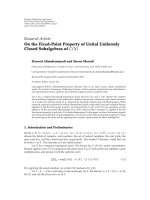
Figure 1 presents an example of a WMN in today’s digital
world.
Many research problems still remain open in WMNs
[1]. Among them, gateway placement is one of the most
challenging but problem. There are some analogous research
results in wired or cellular networks. For example, a number
of studies have been carried out to place web proxies
or server replicas to optimize clients’ performance [2–4].
Another example is the base station placement problem
in cellular networks [5–7]. However, when wireless links
replace wired links and multi-hop communications replace
single-hop communications, a more comprehensive traf-
fic modeling scheme is required to solve the backbone
nodes placement problem in multi-hop wireless networks.
More recently, Bejerano [8] studied gateway placement in
multi-hop wireless networks where network nodes were
partitioned into minimal number of disjoint clusters that
satisfied throughput and delay constraints. Various gateway
or backbone nodes placement algorithms were proposed for
WMNs [9–12]. However, all the above investigation has been
focused on network connectivity of WMNs by deploying the
minimum number of backbone nodes.
Throughput is one of the most critical parameters that
ensure the services of WMNs to meet the requirements of
2 EURASIP Journal on Wireless Communications and Networking
Internet
Internet
accessing
gateway
Internet accessing
gateway
Mesh router / gateway
Mesh clients
Figure 1: A typical WMN.
customers. Unlike all the above research work, in this paper,
given a certain number of gateways, we aim to develop
a gateway placement algorithm to significantly enhance
throughput performance of WMNs. A very similar problem
was addressed in [13], but in that study gateway locations are
either prefixed or searched on a preselected grid in a brutal-
force way. Moreover, uneven distributed traffic demand has
not been studied. In our paper, optimal gateway locations can
be quickly chosen by an intelligent algorithm, which applies
for all the traffic distribution scenarios.
To develop a throughput-oriented gateway placement
algorithm, we first derive a new performance metric called
multi-hop traffic-flow weight (MTW) to take into account
major factors that impact throughput of WMNs. Such
factors include the number of mesh routers, mesh clients,
and gateways as well as traffic demands from mesh clients,
locations of gateways, and interference among gateways.
Based on MTW, an iterative algorithm is proposed to
determine the best location of a gateway. Each time a gateway
is chosen to colocate with the mesh router that has the
highest MTW.
To evaluate the performance of the MTW-based gate-
way placement scheme, a throughput computation model
needs to be derived. However, throughput analysis of
wireless networks is an extremely challenging research topic.
Throughput capacity of multi-hop wireless networks has
been studied in other papers. Gupta and Kumar [14, 15]
derived the per-node throughput capacity for static ad
hoc networks. The throughput capacity of mobile ad hoc
networks was analyzed by Grossglauser and Tse [16]. The
capacity of hybrid ad hoc networks was investigated in [17–
19]. All such results of throughput analysis cannot be applied
to WMNs, because the network architecture of WMNs is
much different from either conventional ad hoc networks
or hybrid ad hoc networks. The work of asymptotic analysis
on the capacity of WMNs has been initiated in [20]where
asymptotic throughput results are obtained by assuming that
the size of the network goes to infinity. Since real networks
always have limited size, these asymptotic results provide
very limited information for practical network design. Thus,
in this paper a nonasymptotic analytical model is derived
to calculate the throughput of WMNs. TDMA scheduling is
assumed to coordinate packet transmissions in mesh clients,
mesh routers, and gateways.
Numerical results based on the throughput computation
model show that the new gateway placement algorithm
greatly enhances the throughput performance of WMNs.
Comparison study is also carried out in this paper to
compare the proposed scheme with other schemes such as
random placement, regular placement, and busiest router
placement. Results illustrate that our proposed gateway
placement algorithm outperforms all these schemes by a
large margin.
The rest of this paper is organized as follows. In Section 2,
a typical WMN model is described and two throughput
metrics for gateway placement are formulized. The new
gateway placement algorithm is proposed in Section 3, while
the throughput computation model needed by this algorithm
is derived in Section 4. The numeric results are obtained
in Section 5 to evaluate the performance of the proposed
algorithm. This paper is concluded in Section 6.
2. System Model and Problem Formulation
2.1. Network Topology. A typical WMN model for Internet
accessing is proposed as follows and is illustrated in Figure 2.
N
c
mesh clients are assumed to be distributed on a square
R
= [0,l]
2
. R is partitioned evenly into (l/l
s
)
2
small cells
R
j
s
= [0,l
s
]
2
(j = 1···(l/l
s
)
2
), and a mesh router is placed
in the center of each cell. Let N
r
denote the number of mesh
routers, then N
r
= (l/l
s
)
2
. In what follows, we will limit the
case of interests to that where 1 <N
r
≤ N
c
, that is, there
are more than one mesh routers and the number of mesh
routers is smaller than that of mesh clients. Mesh routers
constitute a wireless mesh backbone providing a wireless
infrastructure for mesh clients. In each cell, mesh clients are
connected to the mesh router like a star topology; that is,
no direct communication is available among mesh clients,
and the mesh router works as a hub for mesh clients. Such
a WMN is referred as an infrastructure WMN in [1], which
is expected to be very popular in future WMN applications.
Among all the mesh routers, there are N
g
routers wired to
Internet, working as gateways. It is obvious that 1
≤ N
g
≤ N
r
;
that is, the number of gateways cannot exceed the number
of mesh routers. We chose the square grid topologies mainly
because the recent studies on the deployment issues [21]
have shown that square grid topologies are more realistic in
delivering the desired network performance.
Each mesh client is a data source and a data destination.
All mesh clients are equivalent such that they always have
the same amount of packets to send or receive during a
certain time. Unlike mesh clients, mesh routers are neither
EURASIP Journal on Wireless Communications and Networking 3
Mesh router with gateway function
Mesh router without gateway function
Mesh client
l
l
s
Figure 2: Network topology of an infrastructure WMN with
gateways.
data source nor data destination; they only route and forward
data for mesh clients. All traffic is assumed to go through
gateways. Each mesh router is associated with its nearest
gateway such that it relays packets to or from it. Assuming
that the shortest path routing is applied, the nearest gateway
of a mesh router is defined as the gateway that the mesh
router can access to by the minimal number of hops. In
the situation that a mesh router has more than one nearest
gateways, the router will load its traffictoallitsnearest
gatewaysbyroundrobin.Ameshclientissaidtobe
associated with a gateway if its connected router is associated
with the gateway. Hence, traffic load of a mesh client will also
be shared by all its potentially associated gateways.
In this paper the following definitions of communica-
tionswillbefrequentlyused.
(i) Local communications: it is referred as the communi-
cationsbetweenameshrouterandameshclient.
(ii) Backbone communications: it is referred as the
communications between two mesh routers, which
includes the communications between a gateway and
ameshrouter.
(iii) Downlink communications: it is referred as the com-
munications from a gateway to a mesh client, in
which a data packet is first relayed among mesh
routers in backbone communications and is then sent
by a mesh router to one of its connected mesh clients.
(iv) Uplink communications: it is referred as the commu-
nications from a mesh client to a gateway, in which
a data packet is sent in the exact reverse direction as
described in downlink communications.
2.2. Transmission Model. To help elaborate the new gateway
placement scheme and its throughput computation, a trans-
mission model is specified as follows.
Each mesh router is equipped with two radio interfaces:
one transmitting at W
1
bits/s for backbone communications
and the other transmitting at W
2
bits/s for local commu-
nications. Each mesh client transmits at W
2
bits/s in local
communications. We assume that W
1
and W
2
are orthogonal
so that local communications do not interfere with backbone
communications. It should be noted the two radio interfaces
of a mesh router can be two physical radio interfaces or two
virtual radio interfaces. In the later case, only one physical
radio interface is needed for a mesh router and switching
channels in time slots for backbone or local communications
achieves two virtual interfaces.
Moreover, mesh routers can receive packets from only
one sender at a time. The same constraint is imposed on
mesh clients. Transmission and reception can occur in either
time-division duplex (TDD) or frequency division duplex
(FDD), depending on how the physical and MAC layers are
implemented.
In either local communications or backbone communi-
cations, simultaneous transmissions are coordinated by the
Protocol Model as defined in [14]; that is, if a transmission
from node S
i
to S
j
is successful, then the following conditions
must be satisfied: (1)
|S
i
− S
j
|≤r
i
; (2) for every other
transmitting node S
k
, |S
k
− S
j
|≥(1 + Δ)r
k
,wherer
i
and r
k
correspond, respectively, to the transmission range of node
S
i
and S
k
and Δ is a fixed positive constant that represents a
guard zone in the Protocol Model.
2.3. Throughput. In order to evaluate the performance of
gateway placement algorithms, the aggregate throughput and
the worst-case per-client throughput need to be derived. In
this subsection, two problems of throughput maximization
are formulized, which leads to the definitions of two
throughput metrics. The actual framework of computing the
nonasymptotic value of these throughput metrics will be
provided in Section 4.
Problem 1. Optimal gateway placement for maximizing aggre-
gate throughput of WMNs, that is, in the above WMN model,
given N
c
, N
r
, N
g
, W
1
, W
2
and specific clients’ distribution,
routers’ distribution, transmission, scheduling and routing
protocols, N
g
gateways are chosen among N
r
mesh routers
such that
N
c
i=1
TH
i, N
g
(1)
is maximized, where TH(i, N
g
) denotes the per-client
throughput of the ith mesh client when N
g
gateways are
deployed.
Problem 2. Optimal gateway placement for maximizing the
worst-case per-client throughput in the WMN, that is, in the
above WMN model, given N
c
, N
r
, N
g
, W
1
, W
2
and specific
clients’ distribution, routers’ distribution, transmission, and
scheduling and routing protocols, N
g
gateways are chosen
among N
r
mesh routers such that
N
c
min
i=1
TH
i, N
g
(2)
is maximized.
4 EURASIP Journal on Wireless Communications and Networking
3. Multihop Traffic-Flow Weight
Gateway Placement
Adding new gateways can increase throughput in backbone
communications by effectively reducing the average number
of hops each packet needs to access to gateways and reducing
the traffic load on existing gateways. However, the above
benefits can dramatically diminish due to inappropriate
gateway placement, since new gateways will also result in
more interference to existing gateways. Therefore, the best
gateway placement algorithm should not only relieve traffic
load in the network but also introduce minimal interference.
In general a gateway placement scheme must be adaptive
to the deployed number of gateways. A relative small number
of deployed gateways mean a large number of hops that a
packet needs to traverse to gateways, which results in huge
traffic load. Therefore, geometry-balanced placement algo-
rithms, for example, regular placement, may achieve fairly
good results since they can effectively reduce the average
number of hops. In the opposite case, when a relatively large
number of gateways are planned for deployment, placing the
gateways in the areas with the most trafficloadmaybesimply
the best solution.
In this section, an innovative gateway placement algo-
rithm is proposed. It holds all the above-mentioned benefits.
In the algorithm, a traffic-flow weight, denoted by MTW(j),
is calculated iteratively on the mesh router R
j
, j = 1 ···N
r
.
Each time a new gateway will be placed on the router with
the highest weight. The weight computation is adaptive to
the following factors: (1) the number of mesh routers and the
number of gateways, that is, N
r
and N
g
;(2)traffic demands
from mesh clients; (3) the location of existing gateways in
the network; and (4) the interference from existing gateways.
Howfactors(1)to(3)arecapturedinMTWwillbediscussed
in Section 3.1, and the relationship between factor (4) and
MTW will be discussed in Section 3.2. The MTW-based
gateway placement algorithm will be explained while the
MTW is derived in Sections 3.1 and 3.2.
3.1. Adaptive Multihop Traffic-Flow Weight. In the first step
of the algorithm, a variable called gateway radius,denotedby
R
g
, is decided. R
g
is the number of hops from a gateway to its
farthest mesh router. In this paper, (1) is used to estimate R
g
:
R
g
= round
⎛
⎝
N
r
2
N
g
⎞
⎠
. (3)
The rationale of this estimation can be explained as follows.
Considering that a square is divided equally by N
r
cells and
N
g
cells, respectively, then drawing a horizontal line across
the square will statistically meet
N
r
cells and
N
g
cells. For
each N
g
-cell, the line will cross
N
r
/
N
g
N
r
-cells. Therefore,
if a gateway is placed in the center of each N
g
-cell and
a mesh router is placed in the center of each N
r
-cell, we
can estimate that a gateway needs
N
r
/2
N
g
hops to reach
its farthest mesh router. It should be noted that (1) only
provides an estimation, which may not be always precise for
every combination of N
r
and N
g
.
12 6
3
5
5
7
6610
10
10
10
11
10 8
8
888
9
9
4
99
9
(a)
159 202 215 210 162
261201
222
212
160 206 212 202
275 217
237
293
293 316 302
265
165
218266284
(b)
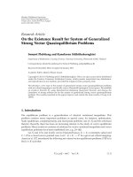
Figure 3: An example of multi-hop traffic-flow weight.
In the second step, local trafficdemandoneachmesh
router, denoted by D(j), j
= 1···N
r
, is calculated. Since
D(j) is actually the traffic demand from all the mesh clients
connected to R
j
and all mesh clients are assumed to be
equivalent in our WMN model, D(j)canberepresented
by the number of mesh clients connected to R
j
. Figure 3(a)
shows an example of D(j) when 200 mesh clients are
uniformly distributed and 25 mesh routers are placed on a
5-by-5 regular grid.
In the third step, MTW( j) is calculated with D( j)andR
g
as follows:
MTW
j
=
R
g
+1
×
D
j
+ R
g
×
trafficdemandonall1−hop neighbors of R
j
+
R
g
−1
×
trafficdemandonall2−hop neighbors of R
j
+
R
g
−2
×
trafficdemandonall3−hop neighbors of R
j
+ ···.
(4)
With MTW( j), the first gateway will be placed on the
router with the highest weight. An example in Figure 3
shows how D(j)andR
g
are combined to determine gateway
placement according to MTW. In this example, there is only
one gateway to be deployed, so N
g
= 1. From (3), we have
R
g
= 3. Therefore, based on D(j)inFigure 3(a), the MTW
is calculated as shown in Figure 3(b). Therefore, the gateway
will be placed in the center mesh router of the WMN that has
the highest MTW weight.
If more than one gateway is to be placed, two additional
steps are needed. Firstly, D(j), j
= 1···N
r
will be
readjusted with R
g
. Assuming that the gateway is placed at
R
j
, the traffic demand value of R
j
and all its neighbors within
(R
g
− 1) hops away will be set as 0, and the value of R
j
’s R
g
-
hop neighbors will be reduced to half. In this way, another
gateway is less likely to be placed in a location near the
existing gateway. Secondly, interfere among gateways should
be counted in the computation of MTW, as discussed in the
next subsection.
EURASIP Journal on Wireless Communications and Networking 5
1
2
3
4
5
6
7
(a)
(1)
(2)
(3)
(4)
1
23
45
67
(b)
0.625
0.375 0.25
0.25 0. 25
0.250.375
(c)
Time slot number 1: 136
Time slot number 2: 27
Time slot number 3: 14
Time slot number 4: 156
Time slot number 5: 27
Time slot number 6: 14
Time slot number 7: 136
Time slot number 8: 25
(d)
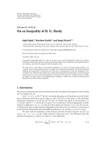
Figure 4: Obtaining the optimal sharing efficiecy on gateways.
3.2. Sharing Efficiency of Gateways. Two gateways interfere
with each other if they are within the distance of Int D-
hops. Int D is defined as Interfering Distance of gateways.
Interfering gateways have to share the same wireless channel
in the backbone communications. An algorithm is developed
in this subsection to derive the sharing efficiency of gateways.
The algorithm holds the two distinct features: (1) full fairness
among gateways will be guaranteed; (2) under the condition
of (1), the efficiency for each gateway will be maximized.
In the first step, the table of nonoverlapping interfering
groups is constructed as follows: (1) each interfering group
appears as a single row in the table and contains a set of
gateways, any two of which interfere with each other; (2) the
group with more gateways always has a smaller row number,
that is, it appears earlier in the table; (3) a group appearing
later must have at least one gateway that is not included by all
the previous groups. For example, seven gateways deployed
on a 5-by-5 mesh backbone grid are shown in Figure 4(a).
When Int D
= 2, the corresponding table of nonoverlapping
interfering groups is illustrated in Figure 4(b) andlistedin
Ta bl e 1 .
In the second step, each gateway is assigned a percentage
value according to the following procedure. (1) Initially all
gateways are assigned with a value of 100%. (2) The table of
non-overlapping interfering groups is searched from the top
row to the last row at a pace of one row per step. (3) In each
step, all gateways in a specific row are split into 2 groups by
a threshold value of (1/the number of gateways in the row).
The first group contains the gateways with a larger value than
the threshold and the second group contains the rest of the
gateways in this row. (4) All gateways in the first group will
then be reassigned a new percentage value calculated as
1
−sum of all the percentage value in the second group
the number of the gateways in the first group
,
(5)
if the new one is smaller than its current value. (5) The
procedures of (3) and (4) are repeated until the end. In
the example shown in Figure 4 and Ta bl e 1 ,gateways3,
4, 5, and 7 are reassigned a percentage value of 25% in
the computation of the first row; gateway 2 is reassigned a
percentage value of 50% in the computation of the second
row; gateways 2 and 6 are reassigned a percentage value of
37.5% in the computation of the third row; gateway 1 is
reassigned a percentage value of 62.5% in the computation
of the fifth row. The final results are shown in Figure 4(c).
The final percentage value assigned to each gateway in the
above algorithm is defined as the optimal sharing efficiency,
denoted by G
eff
(k), k = 1 ···N
g
, because, firstly, it guar-
antees a full fairness among all the gateways, and secondly
it always guarantees the existence of a traffic scheduling
scheme for all the gateways, since in each interfering group,
the sum of the sharing efficiency is always equal or smaller
than 100%. In the scheduling scheme, time slots in backbone
communications are assigned to all gateways such that
successful simultaneous transmissions can be always carried
out in each time slot. Each gateway can be guaranteed to have
a number of time slots, which is equal to the total number
of time slots multiplying the sharing efficiency. Figure 4(d)
shows a TDMA scheduling scheme for the above example.
By taking into account the interference of gateways
via the sharing efficiency, a new gateway can be placed
into the network with the following procedures: (1) from
previous steps in Section 3.1, choosing the router with
the highest weight as a potential location for gateway
placement; (2) reconstructing the table of non-overlapping
interfering groups by adding the potential location into the
consideration; (3) computing the sharing efficiency for the
potential gateway location; (4) readjusting the highest weight
by multiplying the sharing efficiency, that is, MTW
(j) =
MTW(j) × G
eff
(j); and (5) if the new weight is still larger
than the second highest weight, then place the gateway in the
location. otherwise, repeat the above steps from (1) to (5)
until obtaining the location.
4. Traffic Scheduling for
Throughput Computation
In this section, a TDMA scheme is applied for traffic
scheduling. One key benefit of using TDMA is that it
guarantees collision free transmissions. In fact, various
TDMA scheduling schemes are actually used in a few wide
area wireless mesh network testbeds and network standards
such as WiMAX. Based on TDMA scheduling, we provide
a framework of non-asymptotic throughput derivation for
WMNs.
The WMN model indicates that all wireless mesh routers
contend for the same wireless channel of capacity W
1
in
6 EURASIP Journal on Wireless Communications and Networking
Table 1: Optimal sharing efficiency calculation.
Row no. Non-overlapping interfering group
Sharing efficiency
1 2 345 6 7
100% 100% 100% 100% 100% 100% 100%
(1) 3 4 5 7 100% 100% 25% 25% 25% 100% 25%
(2) 2 3 4 100% 50% 25% 25% 25% 100% 25%
(3) 2 4 6 100% 37.5% 25% 25% 25% 37.5% 25%
(4) 1 2 62.5% 37.5% 25% 25% 25% 37.5% 25%
backbone communications, and all mesh routers and mesh
clients contend for capacity W
2
in local communications.
Therefore, the throughput of the ith mesh client when N
g
gateways are deployed, denoted by TH(i, N
g
), is generally
constrained by both W
1
and W
2
. Since W
1
and W
2
are
orthogonal, TH(i, N
g
) can be obtained by computing the
throughput constrained by W
1
and the throughput con-
strained by W
2
separately, that is,
TH
i, N
g
=
min
TH
W
1
i, N
g
,TH
W
2
(
i
)
, i = 1 ···N
c
.
(6)
Here TH
W
1
(i, N
g
) is defined as the throughput of the ith
mesh client in backbone communications when there are
N
g
gateways in the WMN and TH
W
2
(i) is defined as the
throughput of the ith mesh client in local communications.
Note that TH
W
2
(i) is independent of N
g
in the WMN model.
(2) indicates that a feasible per-client throughput can be
achieved by taking the smaller one of TH
W
1
(i, N
g
)and
TH
W
2
(i).
Since W
1
and W
2
should be split for uplink and
downlink communications, respectively, it is assumed that
c
1
W
1
and c
2
W
2
are assigned to downlink communications,
and (1–c
1
)W
1
and (1–c
2
)W
2
are assigned to uplink commu-
nications, where c
1
and c
2
aresomeconstantsbetween0and
1. Generally, throughput of a mesh client should be obtained
as the sum of uplink throughput and downlink throughput.
Choosing the value of c
1
and c
2
requires knowledge on
actual applications running on clients, which is beyond the
objectives of this paper. It is assumed in the following of
this paper that downlink traffic is dominant in the WMN.
Therefore, most of W
1
and W
2
will be assigned to downlink
communications and throughput is decided by downlink
throughput, which is constrained by c
1
W
1
and c
2
W
2
. This
is not an uncommon case in today’s applications of WMNs,
for instance, in the application of Internet access. We shall
note that the methodology proposed in this section can
actually be used to obtain throughput of WMNs when both
uplink traffic and downlink trafficarepresent.However,
with the above simplified model, we can focus on the
illustration of the key ideas without being distracted by trivial
discussions.
4.1. Throughput in Backbone Communications. Time slots
in backbone communications are first assigned to gateways
so that no gateways interfere with each other. The TDMA
scheduling scheme on gateways is assumed to satisfy the
following two conditions: (1) time slots are assigned to each
gateway with full fairness; (2) under the condition of (1),
each gateway should have as much as possible time slots
for successful transmissions. In Section 3.2, an algorithm to
obtain the optimal sharing efficiency on all the gateways,
denoted by G
eff
(k), k = 1 ···N
g
,isprovidedandatraffic
scheduling scheme satisfying the above two conditions is
also constructed. In the scheme, the kth gateway can be
guaranteed to have a number of time slots, which is equal
to the total number of all time slots times G
eff
(k). Hence, the
kth gateway is guaranteed to have an aggregate throughput of
G
eff
(k) × c
1
W
1
in backbone communications. By the TDMA
scheme, interfering gateways share the same wireless channel
while noninterfering gateways can transmit simultaneously.
In the next step, time slots of a gateway will be further
split into small time slots to have the following two proper-
ties: (1) each mesh client associated with the specific gateway
should have separate small time slots for “interference free”
transmissions; (2) each of such mesh clients should achieve
a common throughput in backbone communications, that
is, TH
W
1
(i
1
, N
g
) = TH
W
1
(i
2
, N
g
), if mesh clients i
1
and i
2
are associated with the same gateway. It is assumed that a
mesh router R
j
has N
C
(j)-connected mesh clients and it
located N
hop
(j) hops away from its associated gateway. The
second property requires that R
j
be assigned N
C
(j)×N
hop
(j)
small time slots if there are no simultaneous transmissions
along the way from the gateway to R
j
. Figure 5. shows that
simultaneous transmissions can be scheduled, if R
j
is more
than SRD-hops away from its gateway. SRD is defined as Slot
Reuse Distance, for instance, SRD
= 3inFigure 5. Therefore,
the actual time slot that an R
j
-connected mesh client needs
to meet the second property, denoted by N
hop
(j), has the
following relationship with N
hop
(j):
N
hop
j
= N
hop
j
,ifN
hop
j
< SRD;
N
hop
j
=
SRD, if N
hop
j
≥
SRD.
(7)
With the first property all mesh clients associated with
a specific gateway require total
l
(N
C
(l) × N
hop
(l)) small
time slots for “interference free” transmissions in backbone
communications. Hence, the kth gateway can guarantee the
EURASIP Journal on Wireless Communications and Networking 7
Gateway
R
j
1
2
3
12
3
Figure 5: A TDMA scheduling scheme in backbone communica-
tions with SRD
= 3.
following per-client throughput for all its associated mesh
clients in backbone communications:
TH
g
(
k
)
=
G
eff
(
k
)
×c
1
W
1
l=all associated routers
with the kth gateway
N
C
(
l
)
×N
hop
(
l
)
.
(8)
With the consideration that a mesh router may have more
than one potentially associated gateways and it will use all
these gateways by round robin for fairness, the mesh router
will assign all its time slots equally to its associated gateways.
Therefore, the per-client throughput on the kth gateway can
be modified to
TH
g
(
k
)
=
G
eff
(
k
)
×c
1
W
1
l=all associated routers
with the kth gateway
N
C
(
l
)
×N
hop
(
l
)
÷N
g
(
l
)
,
(9)
where N
g
(l) denotes the number of the associated gateways
with the mesh router R
l
.
Assuming that the ith mesh client is connected with the
mesh router R
j
, finally, the per-client throughput of the ith
mesh client in backbone communications is the averaged
throughput over all its associated gateways:
TH
W
1
i, N
g
=
k=all the associated gateways
with the mesh router R
j
TH
g
(
k
)
N
g
j
. (10)
An example is illustrated in Figure 6 for the throughput
computation in backbone communications. In the example,
there are 5 mesh routers, 2 of which are also gateways,
denoted by G
1
and G
2
. It is assumed that both gateways
have 50% sharing efficiency and all the mesh routers have
10 mesh clients. In the model, the mesh routers R
1
and R
3
are associated with G
1
and G
2
,respectively;R
2
is associated
with both G
1
and G
2
and it uses both the gateways by round
robin. Thus, we have
N
C
(
1
)
= N
C
(
2
)
= N
C
(
3
)
= 10,
N
hop
(
1
)
= N
hop
(
2
)
= N
hop
(
3
)
= 1,
N
g
(
1
)
= N
g
(
3
)
= 1, N
g
(
2
)
= 2.
(11)
R
1
G
1
R
2
G
2
R
3
Figure 6: An example of traffic scheduling in backbone communi-
cations.
By (9), we obtain
TH
g
(
1
)
= TH
g
(
2
)
=
0.5c
1
W
1
15
=
c
1
W
1
30
. (12)
Finally, by (10), we obtain that each of the 30 mesh clients
associated with R
1
, R
2
,andR
3
,respectively,canachieve
throughout of c
1
W
1
/30 bp sin the backbone communica-
tions.
The TDMA traffic scheduling scheme actually guarantees
the full fairness among mesh clients for each gateway. Note
that farther mesh clients from gateways are reserved more
time slots for transmission so that their throughput is not
throttled by closer ones.
The per-client throughput in backbone communications
will be compared with the per-client throughput in local
communications to decide the per-client throughput in the
WMN. Note that if a mesh client is connected directly to
a gateway, its throughput is decided only by the per-client
throughput in local communications.
4.2. Throughput in Local Communications. Separate time
slots are first assigned to different mesh routers so that
simultaneous transmissions can only be carried out in cells
that have enough distance in between; that is, simultaneous
transmissions can only exist in cells that are (
√
CRF −1) cells
apart, where CRF is defined as Cell Reuse Factor.Hence,in
downlink communications, each mesh router can only have
one slot every CRF time-slots, as depicted in Figure 7,here
CRF
= 4.
The above slot is further split into separate small-slots.
Being assigned a different small-slot, each mesh client is
guaranteed to obtain successful reception from its associated
mesh router. Therefore,
TH
W
2
(
i
)
=
c
2
W
2
CRF × N
c
j
, i = 1 ···N
c
.
(13)
With the above TDMA scheme, all the mesh clients
associated with the same mesh router will have the same
throughput in local communications, that is, TH
W
2
(i
1
) =
TH
W
2
(i
2
), if clients i
1
and i
2
are associated with the same
mesh router.
8 EURASIP Journal on Wireless Communications and Networking
12
34
12
34
12
34
12
34
12
34
12
34
12
34
12
34
12
34
Figure 7: A TDMA scheduling scheme in local communications
with CRF
= 4.
4.3. Feasible Throughput in WMN. Combining (6)–(13), a
feasible non-asymptotic throughput of the ith mesh client in
the WMN can be obtained as follows:
TH
i, N
g
=
min
⎧
⎪
⎪
⎪
⎪
⎪
⎨
⎪
⎪
⎪
⎪
⎪
⎩
⎛
⎜
⎜
⎜
⎜
⎜
⎝
k =all the associated gateways
with the mesh router R
j
×
G
eff
(
k
)
×c
1
W
1
l =all associated routers
with the kth gateway
N
C
(
l
)
×N
hop
(
l
)
÷N
g
(
l
)
⎞
⎟
⎟
⎟
⎟
⎟
⎠
/N
g
j
,
c
2
W
2
CRF × N
c
j
⎫
⎪
⎪
⎪
⎪
⎪
⎬
⎪
⎪
⎪
⎪
⎪
⎭
,
(14)
and here ith mesh client is assumed to be connected with
the mesh router R
j
. It is important to note that this non-
asymptotic throughput estimation is more realistic than the
asymptotic throughput that is estimated when the number of
nodes approaches infinity.
When all mesh routers are chosen as gateways, that
is, N
g
= N
r
, throughput of the ith mesh client is only
constrained by local communications, that is, TH(i, N
r
) =
TH
W
2
(i). Therefore, an upper bound is obtained for the
aggregate throughput:
N
c
i=1
TH
i, N
g
≤
N
c
i=1
TH
W
2
(
i
)
=
c
2
W
2
CRF
×
N
r
j=1
u
j
,
(15)
10 10 10
10
1030
3030
60
Figure 8: An example of uneven nodes’ distribution.
where u(j) = 1, if R
j
has at least one connected client; u(j) =
0, if R
j
has no connected client. And an upper bound is also
obtained for the worst-case per-client throughput:
min
i
TH
i, N
g
≤
min
i
TH
W
2
(
i
)
= min
j
c
2
W
2
CRF × N
c
j
=
c
2
W
2
CRF × max
j
N
c
j
.
(16)
The above upper bounds are independent of N
g
.Actu-
ally they are the maximal values that
N
c
i=1
TH(i, N
g
)and
min
i
TH(i, N
g
) can achieve for any number of gateways.
It should be noted that the throughput computation
method is applicable to any gateway placement algorithm;
that is, as long as a gateway placement is given, the
results derived in this section can be used to calculate the
throughput of WMNs.
5. Numeric Results and Discussion
Using the framework of throughput computation derived
in Section 4, throughput of this WMN is studied. In all the
experiments we assume N
c
= 200, N
r
= 36, and l = 1000 m;
that is, there are 200 mesh clients distributed in a square
region of 1000 m
× 1000m; the square is split evenly into 36
small square cells and a mesh router is placed in the center
of each cell. In addition, we assume CRF
= 4, SRD = 3, and
Int D
= 2.
Comparison study is conducted between the proposed
algorithm (MTWP) and the other three gateway placement
algorithms.
(i) Random Placement (RDP): N
g
gateways choose their
placement location randomly on N
r
mesh routers.
(ii) Busiest Router Placement (BRP): N
g
gateways choose
their placement location on the N
r
mesh routers
with the highest trafficdemanddefinedbyD( j), j
=
1 ···N
r
.
EURASIP Journal on Wireless Communications and Networking 9
1614121086420
The number of gateways
Upper bound
W
1
= 10
W
1
= 15
W
1
= 20
W
1
= 25
0
1
2
3
4
5
6
7
8
9
×10
7
The aggregate throughput (bps)
Figure 9: The aggregate throughput by changing the number of
gateways with different channel capacity of mesh routers.
1086420
The number of gateways
Upper bound
MTWP
RDP
BRP
RGP
0
1
2
3
4
5
6
7
8
9
×10
7
The aggregate throughput (bps)
Figure 10: The comparison of the aggregate throughput with
uniformly distributed mesh clients.
(iii) Regular Placement (RGP): as many as possible gate-
ways are placed based on regular patterns and the
rest of them choose their placement location on the
same number of mesh routers with the highest traffic
demand defined by D(j), j
= 1 ···N
r
. Ta b le 2 gives
an example of RGP on a 6-by-6 regular grid.
Given a certain placement algorithm, a number of gate-
ways will be placed on the top of the best-fit mesh routers.
For each algorithm, per-client throughput is calculated based
1086420
The number of gateways
Upper bound
MTWP
RDP
BRP
RGP
0
0.5
1
1.5
2
2.5
×10
5
The worst case of per client throughput (bps)
Figure 11: The comparison of the worst-case per-client throughput
with uniformly distributed mesh clients.
on (14). Then the aggregate throughput and the worst-
case per-client throughput are obtained as described in
Section 2.3. The upper bounds of the above two throughputs
are calculated based on (15)and(16), respectively. Since
mesh clients in all cases follow a random distribution, the
results in all plots are obtained as an average over 200
iterations.
In the first case, we study the relationship between
channel capacity of mesh routers and the number of
gateways. We assume that all mesh clients are uniformly
distributed and each of them can transmit at 10 Mbps in
downlink communications, that is, c
2
W
2
= 10 Mbps. The
aggregate throughput of the WMN versus the number of
gateways is shown in Figure 9, where gateways are placed
by the proposed MTWP algorithm and the channel capacity
ofmeshroutersvariesfrom10Mbpsto25Mbpswith
an increment of 5 Mbps. Our results confirm the fact
that the number of gateways can be dramatically reduced
by using more powerful mesh routers in the backbone;
for example, 6 gateways with mesh router transmitting
at 25 Mbps can achieve much better throughput perfor-
mance than 15 gateways with mesh router transmitting at
10 Mbps.
In the second case, as shown in Figures 10 and 11,we
compare throughput performance of four gateway place-
ment algorithms in the WMN. We assume that all mesh
clients are uniformly distributed and each mesh client
and mesh router can transmit at 10 Mbps and 20 Mbps,
respectively. The results show that the proposed MTWP
algorithm clearly outperforms the other algorithms in both
the aggregate throughput and the worst case throughput.
The regular placement algorithm achieves the second best
results because it is a geometry-balanced algorithm which
10 EURASIP Journal on Wireless Communications and Networking
Table 2: An example for RGP on a 6-by-6 regular grid.
N
g
Gateway placement
1
Choose the busiest router from the location of (3,3), (3,4), (4,3), and (4,4)
2
∼4
Choose the N
g
busiest routers from the location of (2,2), (2,5), (5,2), and (5,5)
5
∼7
Choose the first 4 gateways at the location of (2,2), (2,5), (5,2), and (5,5) and choose the rest on the other
routers with the highest trafficdemand
8
36 routers are split into 4 groups. In each group, any two routers are at least 2-hops away, for example, (1,1),
(1,3), (1,5), (3,2), (3,4), (3,6), (5,1), (5,3), and (5,5) are in one group. Choose the first gateway on the busiest
router and choose the rest 7 gateways on the next 7 busiest routers in the same group with the first one
≥9
36 routers are split into 4 groups as above. Choose the first gateway on the busiest router, then choose the next 8
gateways on the other routers in the same group with the first one, and choose the rest on the other routers with
the highest trafficdemand
1614121086420
The number of gateways
Upper bound
MTWP
RDP
BRP
RGP
0
2
4
6
8
10
12
14
16
18
×10
7
The aggregate throughput (bps)
Figure 12: The comparison of the aggregate throughput with
unevenly distributed mesh clients.
can effectively reduce the average distance between a gateway
and its associated mesh routers.
In the third case, as shown in Figures 12 and 13,we
compare throughput performance of four gateway place-
ment algorithms when mesh clients are distributed unevenly
in the network, as depicted in Figure 8. Note that in each
of the nine regions in Figure 8, nodes are still uniformly
distributed; however, nodes density is very different among
the nine regions. In this case, MTWP algorithm outperforms
the other three algorithms in every single case. Here we
double the channel capacity of mesh clients assuming
that mesh clients and mesh routers can both transmit at
20 Mbps. Otherwise, improvements by gateway placement
algorithms may not be observed since very low throughput
of local communications becomes the major constraint for
throughput performance of the whole WMN, which results
from very high node density in some regions.
In both the second and third cases, as shown in
Figures 10–13, the MTWP algorithm has the biggest
1614121086420
The number of gateways
Upper bound
MTWP
RDP
BRP
RGP
0
0.5
1
1.5
2
2.5
3
×10
5
The worst case of per client throughput (bps)
Figure 13: The comparison of the worst-case per-client throughput
with unevenly distributed mesh clients.
improvement in throughput when the number of gateways
is chosen from five to eight. An explanation is given
as follows: with more than four gateways in a 6-by-6
grid backbone network, gateways start to interfere with
each other. Comparing with the other three algorithms,
MTWP algorithm has a unique mechanism to mitigate such
interference among gateways. Thus, countering interference
among gateways is very critical for a gateway placement
algorithm.
An important problem that WMN service providers
face is the deployment cost involved in setting up the
gateways. Thus, a performance metric to evaluate the cost
of a gateway placement algorithm can be the aggregate
throughput per gateway. Corresponding to Figure 10, the
gateway placement costs are reflected in Figure 14. These
results indicate that there exist an optimal number of
gateways that achieve best tradeoff between the gateway
cost and throughput. More importantly, it is illustrated that
MTWP is the most cost-efficient scheme, since each gateway
EURASIP Journal on Wireless Communications and Networking 11
1086420
The number of gateways
MTWP
RDP
BRP
RGP
0
2
4
6
8
10
12
14
16
×10
6
The aggregate throughput per gateway (bps)
Figure 14: The comparison of the aggregate throughput per
gateway with uniformly distributed mesh clients.
1614121086420
The number of gateways
MTWP
RDP
BRP
RGP
0
0.2
0.4
0.6
0.8
1
1.2
1.4
1.6
1.8
2
×10
7
The aggregate throughput per gateway (bps)
Figure 15: The comparison of the aggregate throughput per
gateway with unevenly distributed mesh clients.
achieves the highest aggregate throughput. For unevenly-
distributed mesh clients, results of throughput per gateway
versus the number of gateways are shown in Figure 15.Again
the MTWP algorithm is the most cost-effective.
6. Conclusion
The problem of gateway placement in WMNs for enhanc-
ing throughput was investigated in this paper. A gateway
placement algorithm was firstly proposed based on multi-
hop traffic weight. A non-asymptotic analytical model was
also derived to determine the achieved throughput by a
gateway placement algorithm. Based on such a model, the
performance of the proposed gateway placement algorithm
was evaluated. Numerical results illustrated the proposed
algorithm achieved much better performance than other
schemes. It was also proved to be a cost-effective solution.
It should be noted that the MTWP algorithm proposed
in this paper did not consider the cross-optimization
between gateway placement and throughput of WMNs.
Thus, the throughput achieved by MTWP is not necessarily
optimal and can be lower than the maximum throughput.
Optimizing gateway placement together with throughput
maximization is our next research goal.
References
[1] I. F. Akyildiz, X. Wang, and W. Wang, “Wireless mesh
networks: a survey,” Computer Networks,vol.47,no.4,pp.
445–487, 2005.
[2] S. Jamin, C. Jin, A. R. Kurc, D. Raz, and Y. Shavitt, “Con-
strained mirror placement on the Internet,” in Proceedings
of the Annual Joint Conference of the IEEE Computer and
Communications Societies (INFOCOM ’01), vol. 1, pp. 31–40,
2001.
[3] B. Li, M. J. Golin, G. F. Italiano, X. Deng, and K. Sohraby, “On
the optimal placement of web proxies in the Internet,” in Pro-
ceedings of the IEEE Conference on Computer Communications
(INFOCOM ’99), vol. 3, pp. 1282–1290, 1999.
[4]L.Qiu,V.N.Padmanabhan,andG.M.Voelker,“Onthe
placement of Web server replicas,” in Proceedings of the Annual
Joint Conference of the IEEE Computer and Communications
Societies (INFO COM ’01), vol. 3, pp. 1587–1596, 2001.
[5] S. V. Hanly, “Algorithm for combined cell-site selection and
power control to maximize cellular spread spectrum capacity,”
IEEE Journal on Selected Areas in Communications, vol. 13, no.
7, pp. 1332–1340, 1995.
[6] R. Mathar and T. Niessen, “Optimum positioning of base
stations for cellular radio networks,” Wireless Networks, vol. 6,
no. 6, pp. 421–428, 2000.
[7] K. Tutschku, “Demand-based radio network planning of
cellular mobile communication systems,” in Proceedings of
IEEE Conference on Computer Communications (INFOCOM
’98), vol. 3, pp. 1054–1061, 1998.
[8] Y. Bejerano, “Efficient integration of multi-hop wireless and
wired networks with QoS constraints,” in Proceedings of the
8th Annual International Conference on Mobile Computing and
Networking (MOBICOM ’02), September 2002.
[9] A. Srinivas, G. Zussman, and E. Modiano, “Mobile backbone
networks—construction and maintenance,” in Proceedings of
the International Symposium on Mobile Ad Hoc Networking and
Computing (MobiHoc ’06), pp. 166–177, 2006.
[10] A. So and B. Liang, “Minimum cost configuration of relay
and channel infrastructure in heterogeneous wireless mesh
networks,” in Proceedings of the International IFIP-TC6 Net-
working Conference, pp. 275–286, 2007.
[11]J.Wang,B.Xie,K.Cai,andD.P.Agrawal,“Efficient mesh
router placement in wireless mesh networks,” in Proceedings
of IEEE International Conference on Mobile Adhoc and Sensor
Systems (MASS ’07), 2007.
[12] B. He, B. Xie, and D. P. Agrawal, “Optimizing the internet gate-
way deployment in a wireless mesh network,” in Proceedings
12 EURASIP Journal on Wireless Communications and Networking
of IEEE International Conference on Mobile Adhoc and Sensor
Systems (MASS ’07), 2007.
[13] F. Li, Y. Wang, and X Y. Li, “Gateway placement for through-
put optimization in wireless mesh networks,” in Proceedings of
IEEE International Conference on Communications (ICC ’07),
pp. 4955–4960, 2007.
[14] P. Gupta and P. R. Kumar, “The capacity of wireless networks,”
IEEE Transactions on Information Theory ,vol.46,no.2,pp.
388–404, 2000.
[15] P. Gupta and P. R. Kumar, “Internets in the sky: the capacity
of three dimensional wireless networks,” Communications in
Information and Systems, vol. 1, no. 1, pp. 33–49, 2001.
[16] M. Grossglauser and D. Tse, “Mobility increases the capacity
of ad-hoc wireless networks,” in Proceedings of the Annual
Joint Conference of the IEEE Computer and Communications
Societies (INFO COM ’01), vol. 3, pp. 1360–1369, 2001.
[17] B. Liu, Z. Liu, and D. Towsley, “On the capacity of hybrid
wireless networks,” in Proceedings of the 22nd Annual Joint
Conference of the IEEE Computer and Communications Soci-
eties (INFOCOM ’03), vol. 2, pp. 1543–1552, 2003.
[18] U. C. Kozat and L. Tassiulas, “Throughput capacity of random
ad hoc networks with infrastructure support,” in Proceedings
of the Annual International Conference on Mobile Computing
and Networking (MOBICOM ’03), pp. 55–65, 2003.
[19] A. Zemlianov and G. De Veciana, “Capacity of ad hoc
wireless networks with infrastructure support,” IEEE Journal
on Selected Areas in Communications, vol. 23, no. 3, pp. 657–
667, 2005.
[20]P.Zhou,X.Wang,andR.Rao,“Asymptoticcapacityof
infrastructure wireless mesh networks,” IEEE Transactions on
Mobile Computing, vol. 7, no. 8, pp. 1011–1024, 2008.
[21] J. Robinson and E. W. Knightly, “A performance study of
deployment factors in wireless mesh networks,” in Proceedings
of IEEE International Conference on Computer Communica-
tions (INFOCOM ’07), pp. 2054–2062, May 2007.