Advances in Optical and Photonic Devices 2011 Part 5 ppt
Bạn đang xem bản rút gọn của tài liệu. Xem và tải ngay bản đầy đủ của tài liệu tại đây (5.27 MB, 25 trang )
Optical Injection-Locking of VCSELs
91
4. Experiments using multimode lasers
4.1 Multimode Edge Emitting Lasers (EELs)
Optically injection-locked lasers are known to overcome many fundamental limitations of
free-running systems. One of the very important improvements proposed by the
employment of the optical injection-locking technique is the side-mode suppression of a
multimode laser (Iwashita and Nakagawa, 1982). Fig. 12 presents the superimposed optical
spectra of a free-running and an injection-locked laser diode. The Fabry-Pérot modes, visible
in the free-running regime, undergo approximately 35 dB suppression when injection-
locked using a DFB laser diode.
Fig. 12. The super-imposed spectra of a free running and an injection locked Fabry-Pérot
EEL. Mode suppression can be observed in the injection locked spectrum.
In the stable locking regime the follower laser frequency is locked to the master laser lasing
frequency. The injection-locked Fabry-Pérot mode therefore becomes dominant and the
unlocked modes are suppressed. Iwashita et. al demonstrated the utilization of this method
for the suppression of mode-partition noise [1]. The employment of optical-injection locking
for side-mode suppression in VCSELs however is not very effective. This is due to the
difference in the side-mode generation mechanism between the EELs and the VCSELs. A
detailed analysis of side-mode generation is presented in the following section.
Single-mode operation of the follower laser however is highly desirable due to another very
important reason. As presented in figure 3.2, the locking-range of an injection-locked laser,
in the “stable operation region”, is dependent on the injected optical power. This effective
locking-range is exploitable only if the follower laser is single-mode. If the follower laser is
multimode, the achievable detuning frequency is limited by the Free Spectral Range (FSR) of
the follower laser. At large detuning frequencies, the master laser might come closer to an
adjacent longitudinal mode and in that case, it will lock the adjacent longitudinal mode
instead of sweeping the entire locking range with previously locked mode. This mode-
hopping reduces the effective “locking” and hence “operation range” of an injection-locked
system.
4.2 Multimode VCSELs
Fig. 13 presents the optical spectrum of a multimode VCSEL. The VCSEL in question is
manufactured by Vertilas with a threshold current of 6 mA and peak output optical power
Advances in Optical and Photonic Devices
92
of 20 mW. The VCSEL chip was powered-up using a probe-station. The master laser is
single-mode Vertilas VCSEL emitting in the 1.55μm range. A comparison with Fig. 14 shows
that optical injection-locking fails to produce an effect similar to that demonstrated
previously on multimode EELs. Although nominal side-mode suppression is observed in
the injection-locked follower VCSEL spectrum, the emission spectrum rests multimode.
Fig. 13. Optical spectrum of an Vertilas multimode “Power” VCSEL. The VCSEL threshold
current is about 6 mA.
Fig. 14. Spectrum of an optically injection-locked multimode Vertilas VCSEL. The threshold
current is about 6 mA. Very feeble side-mode suppression is observed due to injection-locking.
4.3 Experiments using single-mode VCSELs
This can be explained by developing an understanding of the side-mode generation
phenomena in VCSELs. The active region of a VCSEL is very short as compared to that of an
EEL, essentially of the order of the emission wavelength. Consequently, only one Fabry-
Pérot mode exists in the VCSELs, since the physical dimensions of the cavity eliminate the
Optical Injection-Locking of VCSELs
93
possibility of longitudinal multi-mode lasing action. Therefore VCSELs are fundamentally
single-mode emission devices. However, the confinement and guiding of the optical field
thus generated is made very difficult due to a very peculiar VCSEL structural characteristic.
VCSEL design suggests the sharing of a common path for photons and carriers, moving
through the DBRs. This leads to the heating of the DBRs due to carrier flow and results in a
variable refractive index distribution inside the VCSEL optical cavity. The creation of non-
uniform refractive index zones inside the optical cavity leads to different optical paths and
has an overall dispersive effect. This phenomenon is known as “Thermal Lensing”.
The electrons passing through the DBRs tend to concentrate on the edge of the active zone
due to the oxide aperture-based carrier guiding. A higher carrier concentration at the fringes
of the active zone translates into higher photon generation at the edges of the active zone.
Instead of being concentrated in the centre of the optical cavity, in the form of a single
transverse mode, the optical energy is repartitioned azimuthally inside the optical cavity.
The creation of non-uniform refractive index zones within the VCSEL optical cavity,
changes the effective optical path inside the cavity which manifests itself in the form of
undesired side-modes. Since the VCSEL sidemodes are a consequence of spatial energy
distribution, they are referred to as “Spatial” or “Transverse Modes”. Higher bias currents
therefore imply high optical power and in consequence a higher number of transverse
modes. An oxide-aperture is employed in order to achieve optimal current confinement and
to block unwanted transverse modes. The oxide-aperture diameter determines the
multimode or single mode character of a VCSEL. VCSELs having oxide aperture diameters
greater than 5μm exhibit a multimode behaviour.
It can also be inferred from the above discussion that for the type of VCSELs employing the
oxide-aperture technology for optical confinement, single mode VCSELs almost always
have emission powers less than those of multimode VCSELs. Since the Vertilas VCSEL used
here is a high power device, it has a Buried Tunnel Junction (BTJ) diameter of 20μm and is
therefore distinctly multimode. Since optical injection-locking favours single-mode
operation by eliminating longitudinal modes and since the modes generated in VCSELs are
not longitudinal, the employment of optical injection-locking for single-mode VCSEL
operation is not very effective.
4.4 Experiments using vertilas VCSELs
A logical step, after trying optical injection-locking of multimode VCSELs, was to attempt
the injection-locking of single-mode VCSELs. The VCSELs used for initial injection-locking
experiments were manufactured by Vertilas GmbH. These are single-mode, TO-46
packaged, pigtailed, Buried Tunnel Junction (BTJ) devices with an emission wavelength of
1.55μm. The L-I curve of the follower VCSEL is presented in figure 3.5 (a). The mode
suppression ratio between the fundamental and the side-mode is approximately 40 dBs. The
injection-locking experiments using Vertilas VCSELs were simple to carry-out due to the
pigtailed nature of the components that made the optical power-injection inside the follower
VCSEL cavity relatively easy. The well known phenomenon of sidemode suppression (as
demonstrated with EELs and presented in figure 12) was observed. When the VCSEL
satellite mode is optically injection-locked, the fundamental mode undergoes a rapid
diminution and the VCSEL output optical power shifts to the side-mode wavelength.
However, other than being a proof of concept demonstration, this exercise proved to be of
little significance. The real price of this ease of manipulation was paid in terms of a
degraded frequency response.
Advances in Optical and Photonic Devices
94
The TO-46 package cut-off frequency was about 5 Ghz which was well below the
component cut-off frequency (11 GHz). The observation of injection-locked VCSELs’ S
21
response under various injection conditions was therefore not possible.
4.5 Experiments using RayCan VCSELs
The optically injection-locked follower VCSEL S
21
responses presented above provide very
interesting results. Especially the availability of on-chip components allows the observation
of parasitics-free free-running and injection-locked S
21
responses. It was noticed however
that the Master VCSEL is not modulated for these injection-locking experiments and hence
needs not be on-chip.
(a) (b)
Fig. 15. (a) Optical spectrum of an optically injection-locked Vertilas VCSEL. The locking of
fundamental mode further suppresses the side-mode. (b) Optical spectrum of an optically
injection-locked Vertilas VCSEL. The locking of side mode has suppressed the fundamental
lasing mode. Notice the position of the suppressed modes in the two different cases.
The employment of a fibred master VCSEL will facilitate the injection-locking experiments
in the following ways:
• This will allow the utilization of only one probe-station instead of two thus reducing the
test-bench size and minimizing its complexity.
• This will increase the magnitude of available optical power since the coupling losses on
the master VCSEL side would be eliminated.
Also, injection-locking experiments in the static domain such as linewidth, polarization and
RIN measurements could be carried out using fibred follower VCSEL without suffering
from packaging parasitics performance penalties. It was then decided to carry-out injection-
locking experiments using commercially available RayCan VCSELs.
4.6 RayCan VCSELs structure
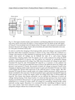
The structure of a 1.3μm RayCan VCSEL is presented in Fig. 6. RayCan VCSELs are bottom-
emitting type, as has been explained above. As far as the incorporation of a bottom-emitting
VCSEL in an optical sub-assembly is concerned, the application of normal integration
techniques such as wire-bonding or flip-chip designs is easily applicable. However, probe-
station testing of bottom-emitting components poses some challenging problems. Bottom-
emission implies the existence of electrodes on the reverse side of the VCSEL chip, as shown
in figure 3.20. This means that in order to power-up the VCSEL, using coplanar probes, the
chip has to be inverted.
Optical Injection-Locking of VCSELs
95
Fig. 16. Bottom-emitting on-chip RayCan VCSEL with 1.3μm operation wavelength.
The chip-inversion, in turn, implies the impossibility of optical power collection with a
single-mode or multimode fibre. On the other hand, if the chip is used in the top-emitting
configuration, it becomes impossible to power-up the chip using probes.
Another problem was the distance between the two electrodes. The probes used for VCSEL
testing have a pitch of 125 μm. However the distance between the two RayCan VCSEL
electrodes is about 300 μm. Without using 300 μm pitch probes, it would have been
impossible to power-up the VCSELs anyway. These two problems were solved by getting
the VCSEL chip integrated to a sub-mount. The sub-mount was prepared by RayCan for
VCSEL integration with a monitoring photodiode, inside a TO-46 package. As per our
demand, the VCSEL chips were integrated to the sub-mounts and delivered to us
unpackaged. Furthermore, the intent of optical injection-locking experiments was
observation of the enhanced S
21
response. This objective was compromised by the
employment of the sub-mount, as the S
21
response was limited by the parasitic transmission
line frequency.
The presence of air-gaps in the VCSEL structure implies lower intrinsic cut-off frequencies.
The inevitable utilization of the sub-mount assembly, combined with the above-mentioned
structural deficiency, renders these VCSELs relatively low frequency operation devices. It is
perhaps due to this reason that the 10 Gbps modules supplied by RayCan employ four
VCSELs in parallel configuration to achieve 10Gbps bit rate, as opposed to Vertilas 10Gbps
modules that are composed of only one VCSEL.
4.7 Injection locking experiments
The availability of fibred components however simplified the test-bench considerably. In
stead of using two probe-stations for master and follower VCSELs respectively, only one
probe-station was used since only the follower VCSEL was used in the on-chip
configuration.
The utilization of a pigtailed master VCSEL also increased the available optical power and
allowed the elimination of the OSA from the injection-locking setup. Fig. 17 presents the
optical injection-locking test-bench used for RayCan VCSEL experiments schematically. The
utilization of a pigtailed master VCSEL made the testbench considerably compact and
increased the available optical power but despite these advantages, the follower VCSEL
injection-locked S
21
spectra do not exhibit very large resonance frequencies. Fig. 18 presents the
S
21
response of an optically injection-locked RayCan follower VCSEL, in the positive frequency
detuning regime. Compared to the free-running responses presented, it is clear that an
Advances in Optical and Photonic Devices
96
increased resonance frequency is observed. Also, due to operation in the positive frequency
detuning regime, the S
21
is un-damped and therefore the resonance peak is very pronounced.
Fig. 17. Schematic representation of the test-bench employed for injection-locking
experiments using RayCan VCSELs emitting at 1.3μm.
Fig. 18. S
21
response of an optically injection-locked RayCan VCSEL emitting at 1.3μm
operating in the positive frequency detuning regime.
Optical Injection-Locking of VCSELs
97
Fig. 19. S
21
response of an optically injection-locked RayCan VCSEL emitting at 1.3μm
operating in the positive frequency detuning regime.
5. Conclusion and discussion
Experimental studies of VCSEL-by-VCSEL optical injection-locking phenomena were
presented in this chapter. It was demonstrated that optical injection-locking suppresses only
the Fabry-Pérot modes of an optical cavity. The transverse modes commonly found in
VCSELs remain largely unaffected by optical injection-locking. VCSEL-by- VCSEL optical
injection-locking was presented using fibred single-mode VCSELs and fundamental and
sidemode suppression phenomena were demonstrated.
Optical injection-locking of on-chip VCSELs was suggested, in order to observe the
parasitics free S
21
response. Three different operation regimes were explored using VCSEL-
by- VCSEL optical injection-locking. Resonance frequencies as high as 7 GHz were
presented for follower VCSELs operating in positive frequency detuning regimes. It was
however observed that positive frequency detuning increases the resonance frequency but
limits the effective bandwidth of the injection-locking system which is not desirable for
VCSEL employment in high bit rate telecommunication system.
The zero or slightly negative detuning regime proposes flat, highly damped S
21
curves. An
increase in injected optical power, while remaining keeping the VCSELs in negative
detuning configuration, results in the increase of effective bandwidth. Effective bandwidths
as high as 10 GHz, using optical injection-locking, have been demonstrated. It must be noted
that the free-running cut-off frequency of the VCSELs used is about 5 GHz. In order to
simplify the optical injection-locking setup, the utilization of a fibred master VCSEL has
been proposed. Such a configuration also increases the effective available optical power.
Optically injection-locked follower VCSEL S
21
response has been presented in different
operating conditions. Experimental results and numerical calculations using the
mathematical model have been compared.
Advances in Optical and Photonic Devices
98
6. References
T. Baba, Y. Yogo, K. Suzuki, F. Koyama, and K. Iga, “Near room temperature continuous
wave lasing characteristics of GaInAsP/InP surface emitting laser,” Electronics
Letters, vol. 29, no. 10, pp. 913–914, May 1993.
A. Bacou, A. Rissons, and J C. Mollier, “Spectral behavior of long wavelength VCSELs,”
SPIE Vertical-Cavity Surface-Emitting Lasers XII, vol. 6908, no. 1, 2008.
A. Bacou, “Caractérisation et Modélisation optoélectronique de VCSEL à grande longueur
d’onde pour sousensembles optiques intégrés,” Ph.D. dissertation, Institut Supérieur
de l’Aéronautique et de l’Espace, 2008.
R. L. Batdorf, G. C. Dacey, R. L. Wallace, and D. J. Walsh, “Esaki Diode in InSb,” Journal of
Applied Physics, vol. 31, no. 3, pp. 613–614, 1960.
A. C. Bordonalli, C. Walton, and A. J. Seeds, “High-Performance Phase Locking of Wide
Linewidth Semiconductor Lasers by Combined Use of Optical Injection Locking
and Optical Phase-Lock Loop,” J. Lightwave Technol., vol. 17, no. 2, p. 328, 1999.
J. Boucart, C. Starck, F. Gaborit, A. Plais, N. Bouche, E. Derouin, L. Goldstein, C. Fortin, D.
Carpentier, P. Salet, F. Brillouet, and J. Jacquet, “1-mW CW-RT monolithic VCSEL at
1.55 μm,” IEEE Photonics Technology Letters, vol. 11, no. 6, pp. 629–631, Jun 1999.
C. A. Burrus, “Indium Phosphide Esaki Diodes,” Solid-State Electronics, vol. 5, p. 357, 1962.
C H. Chang, L. Chrostowski, C. Chang-Hasnain, and W. Chow, “Study of long wavelength
VCSEL-VCSEL injection locking for 2.5-Gb/s transmission,” IEEE Photonics
Technology Letters, vol. 14, no. 11, pp. 1635–1637, Nov 2002.
C H. Chang, L. Chrostowski, and C. Chang-Hasnain, “Injection locking of VCSELs,” IEEE
Journal of Selected Topics in Quantum Electronics, vol. 9, no. 5, pp. 1386–1393, Sept
Oct. 2003.
L. Chrostowski, C H. Chang, and C. Chang-Hasnain, “Reduction of Relative Intensity Noise
and Improvement of Spur-Free Dynamic Range of an Injection-Locked VCSEL,”
The 16th Annual Meeting of the IEEE Lasers and Electro-Optics Society. LEOS 2003, vol.
2, pp. 706–707 vol.2, Oct. 2003.
L. Chrostowski, X. Zhao, and C. Chang-Hasnain, “Microwave Performance of Optically
Injection-locked VCSELs,” IEEE Transactions on Microwave Theory and Techniques,
vol. 54, no. 2, pp. 788–796, Feb. 2006.
L. Chrostowski, F. B., W. Hoffman, M C. Amann, S. Wieczorek, and W. Chow, “40 GHz
Bandwidth and 64 GHz Resonance Frequency in Injection-Locked 1.55 μm
VCSELs,” IEEE Journal of Selected Topics in Quantum Electronics, Vol. 13, No. 5, 2007.
A. G. Chynoweth, W. L. Feldman, and R. A. Logan, “Excess Tunnel Current in Silicon Esaki
Junctions,” Physics Review, vol. 121, p. 684, 1961. C. A. Burrus, “Indium Phosphide
Esaki Diodes,” Solid-State Electronics, vol. 5, p. 357, 1962.
I. Dias, B. Nabet, A. Kohl, J. Benchimol, and J. Harmand, “Electrical and optical
characteristics of n-type-doped distributed Bragg mirrors on InP,” IEEE Photonics
Technology Letters, vol. 10, no. 6, pp. 763–765, Jun 1998.
L. Esaki, “Long journey into tunneling,” Proceedings of the IEEE, vol. 62, no. 6, pp. 825–831,
June 1974.
M. Espana-Boquera and A. Puerta-Notario, “Noise Effects in Injection Locked Laser
Simulation: Phase Jumps and Associated Spectral Components,” Electronics Letters,
vol. 32, no. 9, pp. 818–819, Apr 1996.
N. M. Froberg and K. Y. Lau, “Ultrahigh-efficiency Microwave Signal Transmission Using
Tandem-Contact Single Quantum Well GaAlAs Lasers,” in
Optoelectronic Signal
Processing for Phased-Array Antennas II, vol. 1217, no. 1, 1990, pp. 2–5.
Optical Injection-Locking of VCSELs
99
P. Gallion and G. Debarge, “Influence of amplitude-phase coupling on the injection locking
bandwidth of a semiconductor laser,” Electronics Letters, vol. 21, no. 7, pp. 264–266,
28 1985.
P. Gallion, H. Nakajima, G. Debarge, and C. Chabran, “Contribution of spontaneous
emission to the linewidth of an injection-locked semiconductor laser,” Electronics
Letters, vol. 21, no. 14, pp. 626–628, 4 1985.
M. Grabherr, B. Weigl, G. Reiner, and K. Ebeling, “Comparison of Proton Implanted and
Selectively Oxidized Vertical-Cavity Surface-Emitting Lasers,” in Conference on
Lasers and Electro-optics, 1996. CLEO/Europe., Sep 1996, pp. 165–165.
K. Hasebe, Y. Onishi, and F. Koyama, “Novel polarization controller based on injection-
locked vertical-cavity surface-emitting laser,” IEICE Electronics Express, vol. 2, no. 8,
pp. 274–279, 2005.
C. Henry, N. Olsson, and N. Dutta, “Locking Range and Stability of Injection Locked 1.54μm
InGaAsp Semiconductor Lasers,” IEEE Journal of Quantum Electronics, vol. 21, no. 8,
pp. 1152–1156, Aug 1985.
N. Holonyak and I. Lesk, “Gallium-Arsenide Tunnel Diodes,” Proceedings of the IRE, vol. 48,
no. 8, pp. 1405–1409, Aug. 1960.
J. Jewell, J. Harbison, A. Scherer, Y. Lee, and L. Florez, “Vertical-cavity surfaceemitting
lasers: Design, growth, fabrication, characterization,” IEEE Journal of Quantum
Electronics, vol. 27, no. 6, pp. 1332–1346, Jun 1991.
J. Kahn, “1 Gbit/s PSK homodyne transmission system using phase-locked semiconductor
lasers,” IEEE Photonics Technology Letters, vol. 1, no. 10, pp. 340–342, Oct 1989.
H. Kawaguchi, Y. Yamayoshi, and K. Tamura, “All-Optical Format Conversion Using an
Ultrafast Polarization Bistable Vertical-Cavity Surface-Emitting Laser,” Lasers and
Electro-Optics, 2000. (CLEO 2000). Conference on, pp. 379–380, 2000.
S. Kobayashi and T. Kimura, “Coherence of Injection Phase-Locked AlGaAs Semiconductor
Laser,” Electronics Letters, vol. 16, no. 17, pp. 668–670, 14 1980.
R. Koda, “All-Epitaxial, Long-Wavelength, Vertical-Cavity Surface-Emitting Lasers using
Bipolar Cascaded Active Region for High Differential Quantum Efficiency,” Ph.D.
dissertation, UNIVERSITY OF CALIFORNIA Santa Barbara, 2005.
R. Lang, “Injection Locking Properties of a Semiconductor Laser,” IEEE Journal of Quantum
Electronics, vol. 18, no. 6, pp. 976–983, Jun 1982.
Y. Lee, J. Jewell, A. Scherer, S. McCall, J. Harbison, and L. Florez, “Room-temperature
continuous-wave verticalcavity single-quantum-well microlaser diodes,” Electronics
Letters, vol. 25, no. 20, pp. 1377–1378, Sept. 1989.
C. Lin and F. Mengel, “Reduction of Frequency Chirping and Dynamic Linewidth in High-
Speed Directly Modulated Semiconductor Lasers by Injection Locking,” Electronics
Letters, vol. 20, no. 25, pp. 1073–1075, 1984.
N. Margalit, D. Babic, K. Streubel, R. Mirin, R. Naone, J. Bowers, and E. Hu, “Submilliamp
long wavelength vertical cavity lasers,” Electronics Letters, vol. 32, no. 18, pp. 1675–,
Aug 1996.
M. Ortsiefer, M. Lohner, R. Shau, G. Böhm, and M C. Amann, “Low-resistance InGaAs
tunnel junctions on InP for long-wavelength VCSELs,” in Semiconductor and
Integrated Optoelectronics Conference (SIOE), Cardiff, 1999.
M. Ortsiefer, R. Shau, G. Bohm, F. Kohler, and M C. Amann, “Room-temperature operation
of index-guided 1.55
μm InP-based vertical-cavity surface-emitting laser,”
Electronics Letters, vol. 36, no. 5, pp. 437–439, Mar 2000.
M R. Park, O K. Kwon, W S. Han, K H. Lee, S J. Park, and B S. Yoo, “All-epitaxial
InAlGaAs-InP VCSELs in the 1.3-1.6-μm Wavelength Range for CWDM Band
Advances in Optical and Photonic Devices
100
Applications, ” IEEE Photonics Technology Letters, vol. 18, no. 16, pp. 1717–1719,
Aug. 2006.
J. Piprek, Semiconductor Optoelectronic Devices. Introduction to Physics and Simulation.
Academic Press, 2003.
Y. Qian, Z. Zhu, Y. Lo, H. Hou, M. Wang, and W. Lin, “1.3-μm Vertical-cavity surface-
emitting lasers with double-bonded GaAs-AlAs Bragg mirrors,” IEEE Photonics
Technology Letters, vol. 9, no. 1, pp. 8–10, Jan. 1997.
P. Salet, F. Gaborit, P. Pagnod-Rossiaux, A. Plais, E. Derouin, J. Pasquier, and J. Jacquet,
“Room temperature pulsed operating of 1.3 μm vertical cavity lasers including
bottom InGaAsP/InP multilayer bragg mirrors,” Electronics Letters, vol. Vol. 33 No.
24, pp. 2048–2049, 1997.
N. Schunk and K. Petermann, “Noise Analysis of Injection-Locked Semiconductor Injection
Lasers,” IEEE Journal of Quantum Electronics, vol. 22, no. 5, pp. 642–650, May 1986.
R. Shau, M. Ortsiefer, J. Rosskopf, G. Boehm, C. Lauer, M. Maute, and M C. Amann, “Long-
wavelength InPbased VCSELs with buried tunnel junction: properties and
applications,” SPIE, Vertical-Cavity Surface- Emitting Lasers VIII, vol. 5364, no. 1,
pp. 1–15, 2004.
T. Simpson, J. Liu, and A. Gavrielides, “Small-signal analysis of modulation characteristics
in a semiconductor laser subject to strong optical injection,” IEEE Journal of
Quantum Electronics, vol. 32, no. 8, pp. 1456–1468, Aug 1996.
H. Soda; K. Iga, C. Kitahara, and Y. Suematsu, “GaInAsP/InP Surface Emitting Injection
Lasers,” Japanese Journal of Applied Physics, vol. 18, no. 12, pp. 2329–2330, 1979.
H K. Sung, T. Jung, D. Tishinin, K. Liou, W. Tsang, and M. Wu, “Optical Injection- Locked
Gain-Lever Distributed Bragg Reflector Lasers With Enhanced RF Performance,”
IEEE International Topical Meeting on Microwave Photonics. MWP’2004., pp. 225–228,
Oct. 2004.
A. Syrbu, V. Iakovlev, G. Suruceanu, A. Caliman, A. Mereuta, A. Mircea, C A. Berseth, E.
Diechsel, J. Boucart, A. Rudra, and E. Kapon, “VCSELs Emitting in the 1310- nm
Waveband for Novel Optical Communication Applications,” SPIE Vertical-Cavity
Surface-Emitting Lasers IX, vol. 5737, no. 1, pp. 167–173, 2005.
A. Syrbu, V. Iakovlev, G. Suruceanu, A. Caliman, A. Rudra, A. Mircea, A. Mereuta, S.
Tadeoni, C A. Berseth, M. Achtenhagen, J. Boucart, and E. Kapon, “1.55-μm
optically pumped wafer-fused tunable VCSELs with 32-nm tuning range,” IEEE
Photonics Technology Letters, vol. 16, no. 9, pp. 1991–1993, Sept. 2004.
H. Toba, Y. Kobayashi, K. Yanagimoto, H. Nagai, and M. Nakahara, “Injection-locking
Technique Applied to a 170 km Transmission Experiment at 445.8 Mbit/s,”
Electronics Letters, vol. 20, no. 9, pp. 370–371, 26 1984.
K. J. Vahala, M. A. Newkirk, and T. R. Chen, “The Optical Gain Lever: A Novel Gain
Mechanism in the Direct Modulation of Quantum Well Semiconductor Lasers,”
Applied Physics Letters, vol. 54, no. 25, pp. 2506–2508, 1989.
G. Yabre, H. De Waardt, H. van den Boom, and G D. Khoe, “Noise Characteristics of Single-
Mode Semiconductor Lasers Under External Light Injection,” IEEE Journal of
Quantum Electronics, vol. 36, no. 3, pp. 385–393, Mar 2000.
X. Zhao, M. Moewe, L. Chrostowski, C H. Chang, R. Shau, M. Ortsiefer, M C. Amann, and
C. Chang-Hasnain, “28 GHz Optical Injection-Locked 1.55μm VCSELs,” IEE
Electronic Letters, vol. Vol. 40 No. 8, 15 April 2004.
X. Zhao, E. K. Lau, D. Parekh, H K. Sung, W. Hofmann, M. C. Amann, M. C. Wu, and C. J.
Chang-Hasnain, “107- GHz Resonance Frequency of 1.55μm VCSELs Under Ultra-
high Optical Injection Locking,” in OSA/CLEO, 2008.
6
Tunable, Narrow Linewidth, High Repetition
Frequency Ce:LiCAF Lasers Pumped by the
Fourth Harmonic of a Diode-Pumped Nd:YLF
Laser for Ozone DIAL Measurements
Viktor A. Fromzel, Coorg R. Prasad, Karina B. Petrosyan, Yishinn Liaw,
Mikhail A. Yakshin, Wenhui Shi, and Russell DeYoung
1
Science and Engineering Services, Inc.
1
NASA Langley Research Center
USA
1. Introduction
Ozone plays a crucially important role in all aspects of human life, although it is only a trace
gas present in the middle and low atmosphere. Variations in ozone concentration in the
stratosphere have an affect on the protection of the earth’s biosphere from the harmful
portion of the Sun’s ultraviolet rays. Tropospheric ozone initiates the formation of
photochemical smog and in high concentrations is harmful to human health and vegetation.
Also ozone has a significant influence on the earth radiation budget. Human activities have
produced adverse effects on atmospheric ozone distribution, which it left unchecked could
lead to catastrophic changes to the biosphere . Hence the continuous measurement of ozone
with good spatial resolution over large regions of the globe is an important scientific goal. A
remote sensing technique for the monitoring of ozone concentration based on differential
absorption lidar (DIAL) has been established as a method providing rapid and precise time
and spatial resolutions [Browell, 1989, Richter, 1997]. Ozone absorbs strongly in the UV over
the 240 – 340 nm region and also in the IR at near 9.6 μm. A two-wavelength differential
absorption technique in the UV is commonly used for ozone measurement. After obtaining
the lidar signals at two neighboring wavelengths (on- and off-line), the differential
absorption due to ozone is obtained by taking the ratio of the two signals to eliminate the
contribution to extinction from scattering commen to both signales. Since the ozone
absorption in UV exhibits a smooth band structure, the separation between the on- and off-
line wavelengths is required to be a few nanometers.
A number of ground-based [Profitt & Langford, 1997] and aircraft-based DIAL [Richter et
al.,1997] systems for monitoring ozone concentrations in the planetary boundary layer, the
free troposphere and the stratosphere have been developed by research groups all over the
world [McGee et al, 1995, Mc Dermit et al,1995, Carswell et al,1991, Sunesson, et al,1994].
Most of the ground-based ozone DIAL instruments utilize large excimer gas lasers and
Raman wavelength shifters, or flashlamp pumped frequency tripled and quadrupled
Nd:YAG lasers and dye lasers, which are large complex systems requiring considerable
Advances in Optical and Photonic Devices
102
maintenance. Many different approaches have been used to improve the efficiency and
reduce the size and complexity of the UV lasers required, for example, for airborne ozone
DIAL systems. These systems consist of multi-stage solid-state laser systems involving
Nd:YAG pump lasers, and some combinations of optical parametric oscillators, or
Ti:Sapphire lasers and frequency mixers and solid-state Raman frequency shifters [Richter,
1997, Profitt & Langford, 1977]. However, all of them are still large, and/or complex and
they present enormous challenges for adapting them to autonomous operation.
In conventional lidar systems, high energy laser pulses (~100 mJ) are utilized to obtain a
sufficiently large lidar signal to achieve adequate signal to noise ratio (SNR). A different
approach can be used, wherein a much smaller laser energy (~ 1 mJ) is sufficient to achieve
good lidar performance. This calls for a much smaller all-solid-state laser system that makes
it possible to conform to the playload bay constraints of a small aircraft or other small
movable platform. By operating the laser at much higher pulse repetition rate (PRR = 1
kHz), the average transmitted power (1 W) is maintained at the same level as that of the
bigger laser (100 mJ, 10 Hz, 1 W), despite the much smaller laser energy output (1 mJ) per
pulse. The smaller resulting signal is effectively measured by a low noise photon counting
PMT detection system, whose dark noise counts are in the 10 to 100 Hz range, making the
detector noise negligible. By averaging the signal over a few seconds it is possible to achieve
adequate SNR by reducing the contribution of the signal shot noise to SNR. Overall system
size and complexity are reduced by this approach making the system rugged, compact and
easy to maintain. The recent advances in compact diode-pumped solid state lasers provide
an attractive option for the development of compact and effective laser transmitter for ozone
lidar. While the DPSS lasers are suited for providing only moderate pulse energies, they can
operate at high pulse repetition rates of several kHz to produce reasonably high average
power. It is possible to generate tunable UV output starting with the UV DPSS laser, by two
different techniques both of which are now commercially available. The first method
involves pumping an OPO with a frequency tripled Nd:YAG (355 nm) to generate
continuously tunable output spanning 560 to 630 nm and then frequency doubling it to
obtain the required range of 280 to 315 nm. But the efficiency of this system is very low in
view of the multiple non-linear conversion steps. The second method is simpler and more
efficient, and involves a Ce:LiCAF laser [Stamm, et al, 1997, Govorkov, et al, 1998, Fromzel
& Prasad, 2003] pumped by an appropriate commercially available frequency quadrupled
diode-pumped Nd laser to provide direct UV tunability.
In this chapter, a new development of all-solid-state Ce:LiCAF tunable UV laser (280nm –
315nm), which utilizes a single step conversion of the pump wavelength in Ce:LiCAF
crystal, when pumped by frequency quadrupled diode-pumped Nd:YLF laser is described.
This laser is the central component of a very compact ozone DIAL system. With moderate
(~1mJ) pulse output but high pulse repetition rate (1 kHz) this laser system has a good
performance capability. This laser is a further development of a previously reported
Ce:LiCAF laser producing ~ 0.5 mJ pulse output at 1 kHz with a 46% conversion efficiency
[Fromzel & Prasad, 2003].
2. Requirements to laser transmitter for DIAL ozone measurement
Specific character of ozone absorption line and its distribution in atmosphere as well as
necessary accuracy of the ozone DIAL measurements determine requirements to parameters
of the laser transmitter (energy, PRF, pulse duration, integration time). To establish this
Tunable, Narrow Linewidth, High Repetition Frequency Ce:LiCAF Lasers Pumped
by the Fourth Harmonic of a Diode-Pumped Nd:YLF Laser for Ozone DIAL Measurements
103
relationship, we will consider basic factors which have influence on this accuracy. As it was
mentioned above, in DIAL measurements the differential resonant absorption K(λ
n
) - K(λ
f
)
is obtained by taking the ratio of two atmospheric backscattered signals received by the
lidar at the on- and off- wavelengths λ
n
and λ
f
. from range R. Ozone concentration is then
calculated from the mean differential absorption coefficient K for the range cell layer of
thickness ΔR by using the known ozone differential absorption cross section Δσ = (σ
n
- σ
f
)
where σ
n
and σ
f
are absorption cross sections at the on- and off-line wavelengths. A number
of papers have analyzed the sensitivity and accuracy of the DIAL technique [Ismail &
Browell, 1989, Korb et al, 1995]. The accuracy of the ozone concentration n
O3
measurement is
calculated by using the relation [Grant, et al, 1991]:
1/2
3
O
3
OO s
3
1
n
2 R (SNR)
nn N
σ
Δ
=
ΔΔ
(1)
here N
s
is the number of laser shots, and SNR is the signal to noise ratio of the DIAL
measurement which includes the SNR of both the on-line and off line signals. The accuracy
of the measurement is thus improved by: averaging over larger number shots, increasing
the range cell size, increasing the differential absorption and increasing the signal to noise
ratio of the measurement. The parameters which determine the range are: the ozone
differential absorption cross section; the distribution of ozone along the path at the time of
the measurement; other sources of extinction, such as aerosol loading, fog, etc; the choice of
the on- and off-line wavelengths for ozone. From equation (1), it is seen that the accuracy
and the range resolution can be improved by choosing the wavelengths so as to provide a
large differential absorption cross section (i.e., a large Δσ). However this also makes the
differential scattering cross section: Δα = α(λ
n
) - α(λ
f
) large. Correcting for this requires
knowledge of the molecular and aerosol distributions also. Furthermore, the signal strength
depends on the atmospheric extinction. Hence the choice of optimal wavelength depends
on a number of parameters, which include: the required range, range resolution, temporal
resolution (i.e., measurement time), measurement accuracy, and the expected spatial
distribution of ozone in the atmosphere.
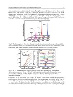
Figure 1 shows the ozone absorption spectrum between 240 and 340 nm. Below 300 nm,
absorption is dominated by the Hartley continuum superimposed by weak Hartley bands.
Band structures seen at wavelengths longer than 300 nm are the Huggins bands. While the
strongest absorption occurs at 260 nm these wavelengths will be completely attenuated after
traveling a short distance and are therefore unsuitable for achieving significant range.
Conversely, wavelengths longer than 300 nm are able to penetrate into the high ozone
concentrations that are characteristic of the stratosphere, but give small differential
absorption signals at the typical tropospheric ozone concentrations. Further, since the
absorption cross sections in the Huggins bands also vary significantly with temperature, this
region of the spectrum is not very useful for tropospheric measurements where the
temperature is highly variable.
Thus, the optimal wavelength range for tunable ozone laser transmitter depends on
atmospheric region of interest setting in the UV spectrum between 280 and 300 nm.
Comparison of calculated ozone lidar performance for two types of UV lasers operating in
the required wavelength region with different characteristics: laser with low energy but
high PRF (1 mJ/pulse, 1kHz) and photon counting for detection and laser with high energy
but low PRF (100 mJ, 10 Hz) and conventional analog detection shows that the low energy
Advances in Optical and Photonic Devices
104
Fig. 1. Ozone absorption spectrum in UV.
laser gives a much higher SNR for all cases of lidar operation. The feasibility of such
approach for ozone DIAL - using a low energy, high PRF laser along with photon counting
detection have been also demonstrated experimentally [Prasad, et al, 1999]. The Ce:LiCAF
laser, which is the best suited for modest energy outputs in the range of 1 to 10 mJ/pulse,
presents a very effective direct method of generating the required wavelengths. The
principal reasons for this are:
1. Laser linewidths of the order of 0.2 nm are adequate for ozone DIAL. Hence a fairly
simple Ce:LiCAF laser system can be designed with a single intra-cavity prism for
generating tunable wavelength with the necessary linewidth, with no need for highly
selective dispersive elements.
2. The spectral bandwidth of the pump laser does not have to be narrow, because of the
broad absorption spectrum of Ce:LiCAF material.
3. Directly tunable laser allows rapid change of wavelength, as it required in hopping
from on- to off-wavelengths.
3. Spectroscopic and thermo-mechanical characteristics of Ce:LiCAF
crystals
Cerium doped crystals Ce:LiCaAlF
6
and Ce:LiSrAlF
6
(Ce:LiCAF and Ce:LiSAF) are well
established as efficient laser media, which can operate directly in the UV region. Both
Ce:LiCAF and Ce:LiSAF crystals demonstrated good conversion efficiency (up to 46%) when
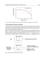
pumped by the fourth harmonic of Nd:YAG or Nd:YLF laser (266 or 262 nm). Figure 2
shows the spectral absorption and fluorescence of Ce3+ in LiCAF and LiSAF. Their strong
absorption at 266 nm (~ 7.5 x 10
-18
cm
2
for π-polarization), broad emission spectrum (280 –
325 nm), high emission cross-section (~ 6.8 x 10
-18
cm
2
for Ce:LiCAF at 290 nm for π-
polarization), and broad tunability (280 -328 nm) make them well suited for ozone DIAL
Tunable, Narrow Linewidth, High Repetition Frequency Ce:LiCAF Lasers Pumped
by the Fourth Harmonic of a Diode-Pumped Nd:YLF Laser for Ozone DIAL Measurements
105
Fig. 2. Polarized absorption and emission spectra of Ce:LiSAF and Ce:LiCAF (π-parallel and
σ-perpendicular to the optical axis)
application. Since the cross-section for absorption at 266 and 262 nm are fairly high, the
Ce3+ dopant concentration of a few percent (1 – 4%) is enough for complete absorption of
the pump. Of the two, Ce:LiCAF is better suited for the high PRF operation, because its
spectroscopic properties are slightly better, it is more mechanically robust, and has much
better solarization properties for withstanding high power pumping at 266 or 262 nm than
Advances in Optical and Photonic Devices
106
that of Ce:LiSAF. The fluorescence lifetime both Ce:LiCAF and Ce:LiSAF crystals are short
(27 and 25 ns, respectively). This implies that the nanosecond pulse durations are required
for pumping of Ce:LiCAF (or Ce:LiSAF) lasers and the laser output is gain-switched by the
pump laser pulse. Also it means that a short resonator is preferred for the Ce:LiCAF laser.
The thermal conductivity of both LiCAF and LiSAF are low and anisotropic in nature (5.14 -
4.58 and 3.09 - 2.9 W/m
o
C, respectively). Thus even for the low thermal loading (~ 1 W), a
noticeable temperature gradient is set up within the crystal. Considering a 3.5% Ce:LiCAF
crystal of 8 x 3 x 10 mm (thickness 3 mm), the calculated temperature rise in the crystal will
be as ΔT ~ 17
0
C.
4. Diode-pumped frequency quadrupled Nd:YLF laser
From our previous experience with designing of a tunable Ce:LiCAF laser producing 0.5 mJ
pulse energy at 1 kHz PRF, it was estimated that in order to obtain ~1 mJ/pulse UV tunable
output from Ce:LiCAF laser the pump Nd:YAG or Nd:YLF laser has to provide pulse
energy in excess of ~ 11 - 12 mJ in a TEM
00
beam profile at the second harmonic (532 or 527
nm) that will allow to have ~ 2.8 -3.0 mJ/pulse at the forth harmonic (266 or 263 nm). Such
TEM
00
-mode green laser was developed by Positive Light company on the base of the
commercial multomode Nd:YLF Evolution 30 laser and supplemented by us with the fourth
harmonic module (263 nm).
The optical layout of the Nd:YLF laser with the intracavity frequency doubling (Evolution –
TEM
00
) is shown in Figure 3. It consists of a Nd:YLF laser rod that is side-pumped by laser
diode arrays. Two high reflective end mirrors M1 and M2 (HR @ 1053nm) form the Nd:YLF
laser resonator. The resonator includes a reflective telescope (mirrors TM1 and TM2) that
serves to increase the beam size incident on the Nd:YLF crystal. The laser beam is then
intracavity frequency doubled by a non-critically phase matched LBO crystal and delivers
an output green beam (527nm) through the harmonics separating mirror, which is highly
transparent at 527 nm and highly reflecting at 1053nm. An acousto-optical Q-switch
performs Q-switched laser operation at 1 kHz repetition rate. The LBO doubling crystal is
placed in a temperature regulated oven (154ºC) to achieve the non-critical phase matching
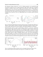
conditions. Figure 4 shows the 527 nm output performance for the frequency doubled
diode-pumped Nd:YLF laser, while Figures 5 shows a temporal pulse profile of the
Evolution TEM
00
laser. It may be noted that the pulse duration is very long and with a half
width (FWHM) slightly smaller than 100 ns, when diode pump current is 24 Amp (close to
Fig. 3. Optical schematic of the intra-cavity frequency doubled diode pumped Nd:YLF
TEM
00
pump laser.
Tunable, Narrow Linewidth, High Repetition Frequency Ce:LiCAF Lasers Pumped
by the Fourth Harmonic of a Diode-Pumped Nd:YLF Laser for Ozone DIAL Measurements
107
Fig. 4. Intracavity doubled green (527 nm) output of diode pumped Nd:YLF laser.
Fig. 5. Temporal profile of the green (527 nm) output pulse of the pump Nd:YLF laser
the maximum of pump current). This long pulse duration is caused by a large length of the
laser resonator (~2 m) and also by the fact that the output coupling of resonator is not
optimal, because the only load for the resonator is the second harmonic generation.
Measurement of spatial profile of the green beam showed that the output beam being very
close to the TEM
00
mode (M
2
~ 1.5) at the same time exhibited a significant amount of
astigmatism, with the beam divergence being about 1 x 1.5 mrad in the X and Y directions,
respectively. The second harmonic output beam (527 nm) measured at the output window
of the laser was slightly elliptic with a diameter of about 0.9 x 1.1 mm for an output of 12 mJ.
Advances in Optical and Photonic Devices
108
The second step in building of appropriate UV pump laser for Ce:LiCAF was development of
an efficient CLBO fourth harmonic generator for a 1 kHz, diode-pumped Nd:YLF laser. CLBO
is well established as the nonlinear material of choice [Mori, et al, 1995] for efficient fourth
harmonic conversion of diode-pumped solid-state neodymium lasers with moderate pulse
energies but high average powers and high PRF. CLBO has a high nonlinear coefficient and a
large temperature and angular acceptance. However, CLBO is highly hygroscopic [Taguchi, et
al, 1997] in nature and thus any exposure of the crystal to humid (>20%) atmospheric
conditions causes rapid degradation of the crystal surface, which can lead to a reduced
performance and/or optical damage. A simple technique to avoid the problems associated
with CLBO crystal is to maintain the crystal at >150ºC, so that atmospheric humidity does not
degrade the crystal. To avoid the crystal degradation, a special crystal ceramic oven for
maintaining the crystal temperature at temperature of ~152ºC has been constructed and was
heated all the time being supplied from a battery backed UPS power source.t should be noted
that the Evolution TEM
00
laser output was no optimum for obtaining the best fourth harmonic
conversion efficiencies because its pulse duration was fairly long (~ 100 ns) and the beam was
not true TEM
00
-mode showing some astigmatism: different beam divergences in the x- and y-
directions. In spite of the non-optimal 527 nm beam, a fairly high fourth harmonic conversion
efficiency (~ 25%) have been achieved in the 15 mm long uncoated CLBO crystal by using
mode matching optics. At this output, the mean incident energy density on the CLBO crystal
was ~ 25% lower than the damage threshold and the CLBO crystal was operated in a safe
damage free regime. Figure 6 shows the fourth harmonic energy output as a function of the
diode pump current for the Nd:YLF laser. At maximum diode current of the Nd:YLF laser of
25 A, the fourth harmonic output was as high as 2.85 mJ/pulse.
Fig. 6. Output from the optimized CLBO fourth harmonic generator shown as a function of
the diode current for pump green laser.
Tunable, Narrow Linewidth, High Repetition Frequency Ce:LiCAF Lasers Pumped
by the Fourth Harmonic of a Diode-Pumped Nd:YLF Laser for Ozone DIAL Measurements
109
5. Ce:LiCAF tunable UV laser
The optical schematic of the Ce:LiCAF laser is shown in Figure 7. A pair of CaF
2
rectangular
prisms was used for separation of the second and fourth harmonic pump beams and for
beam folding. After that the incoming 263 nm UV pump beam was split by a fused silica
beam splitter (40% and 60%) into two parts and directed to the Ce:LiCAF crystal faces by
four 100% reflecting folding mirrors. The pumped spot size on the Ce:LiCAF crystal has an
elliptical shape with dimensions of ~ 0.4 x 0.65 mm. Pump spot sizes on the Ce:LiCAF
crystal were chosen carefully to avoid optical damage of the crystal, to obtain good
conversion efficiency and to provide TEM
00
operation of Ce:LiCAF laser. A Brewster cut
3.5% doped Ce:LiCAF crystal with dimensions of 2 mm (thickness) x 8 mm (width) x 10 mm
(length) is pumped from both faces. The measured absorption of this crystal at 263 nm (π-
polarization) was found to be k
263
= 4.47 cm
-1
, and ~ 98% of the incident pump power is
absorbed in the crystal. The Ce:LiCAF crystal is mounted on a copper crystal holder heat
sink which is maintained at about 20°C. The Ce:LiCAF laser resonator consists of a flat
mirror (HR @ 280-320 nm) and a curved output coupler ( R
out
= 0.6 @ 280-320 nm, RoC = 1
m) with an intra cavity fused silica (suprasil) prism as a wavelength selector which results in
a linewidth of 0.15 – 0.2 nm. The pumping beams are focused into the Ce:LiCAF crystal by
means of two fused silica lenses (200 mm focal length). The tilt angle between the pump
beams and the Ce:LiCAF laser beam is ~ 2.5º. Wavelength tuning of the laser is performed
by rotation of the flat HR mirror of the resonator in horizontal plane. Because direction of
the beam between output coupler and Ce:LiCAF crystal stays unchangeable, such tunable
laser resonator design provides output beam pointing stability and collinearity better than
+/- 0.05 mrad whereas wavelength of the laser is tuned. The length of the resonator is ~ 12
cm. A slightly off-axis pumping scheme is used here. This configuration provides a
significant advantage by spatially separating the pump and laser beams so that the pump
beam does not have to pass through the laser mirrors or other optical components of the
laser thus avoiding a common problem of optical damage caused by the pump beam.
Fig. 8. Optical layout for the double-side pumped Ce:LiCAF laser.
Advances in Optical and Photonic Devices
110
6. Ce:LiCAF laser performance
Figure 9 shows the input - output performance of the Ce:LiCAF laser at wavelength of 290
nm with narrow wavelength bandwidth of ~ 0.15 nm when it is pumped by the FH laser
beam at 263 nm with a pulse repetition rate of 1 kHz. Output pulse energy 1 mJ/pulse was
obtained from the Ce:LiCAF laser when the total incident pump pulse energy on both faces
of the laser crystal was 2.86 mJ/pulse. In our experiments, the slope efficiency is ~ 45%,
which was found to be about 90% of the theoretical maximum value for the laser [Fromzel &
Prasad, 2003]. This result shows that there is nearly full utilization of the pump energy.
Fig. 9. Input-output performance of the Ce:LiCAF laser pumped from two sides by the
fourth harmonic of Nd:YLF laser.
Figure 10 shows the typical temporal shape of the Ce:LiCAF laser pulse. The upper trace is
the shape of the pump pulse at 263 nm and the lower trace is the corresponding Ce:LiCAF
output pulse. It is noted that in spite of a short pulse duration, typical for Q-switched lasers,
the Ce:LiCAF laser operates to the point at free running (gain-switch) regime. It can be clear
seen from the fact that the Ce:LiCAF laser output pulse exhibits typical for free running
laser operation transient behavior (relaxation oscillations). Thus the pulse length of
Ce:LiCAF depends on the pump pulse length. Also shown is the pump laser pulse, and by
comparing the two, the build up time for the Ce:LiCAF pulse is seen to be about 48 ns.
The transverse beam shape of the Ce:LiCAF laser output was measured with a beam
profiler. It was found that the output laser beam has a true TEM
00
-mode distribution (M
2
~
1.1) and the profiles are smooth without any hot spots.
Ability of Ce:LiCAF laser to be directly wavelength tuning is one of the advantages of this
UV laser, which allows rapid change of wavelength, as it required in hopping from on- to
off-line wavelengths, or for sensing ozone at different altitudes. The output wavelength of
Ce:LiCAF laser was tuned by rotating the HR tuning mirror which was mounted on a rotary
mirror mount. The laser wavelength and linewidth were determined by the intra-cavity
dispersing prism. Figure 11 shows a sample laser tuning curve, which was obtained by
Tunable, Narrow Linewidth, High Repetition Frequency Ce:LiCAF Lasers Pumped
by the Fourth Harmonic of a Diode-Pumped Nd:YLF Laser for Ozone DIAL Measurements
111
Fig. 10. Shape of the pump UV pulse (upper trace) and the Ce:LiCAF laser output pulse
(lower trace).
Fig. 11. Tuning curve of the Ce:LiCAF laser.
Advances in Optical and Photonic Devices
112
tuning over a broad spectral region from 281 nm to 316 nm while the 263 nm pump energy
was ~ 2 mJ/pulse. Laser linewidth as measured with the Ocean Optics grating spectrometer
with a resolution of 0.065 nm was approximately 0.15 – 0.2 nm, when a fused silica
dispersing prism was used. The maximum laser output occurred at a wavelength of ~ 290
nm, the second much more weak maximum of laser output corresponded to ~ 308 nm. By
using a different prism material with a larger dispersion, such as, sapphire the linewidth can
be reduced. With a sapphire dispersion prism the linewidth was reduced to ~0.1 nm. The
angular motion required for tuning over 10 nm is approximately 0.3 for fused quartz and
about 0.6 for sapphire.
It can be concluded from Figure 11 that output pulse energy of the Ce:LiCAF laser reduces
approximately four times regarding the maximum of 1 mJ/pulse output at ~ 290 nm, when
laser wavelength is tuned to ~ 284 nm or to ~ 297 nm on the short- and long-wavelength
edge of the tuning curve, respectively.
7. High speed wavelength tuning of Ce:LiCAF laser
Ce:LiCAF laser using as a transmitter for lidar has to supply lidar with both the on- and off-
line wavelengths. As it was shown above, wavelength tuning of Ce:LiCAF laser was
achieved by changing the angle of the rear mirror. A rapid tuning of the laser output
wavelength from shot to shot at pulse repetition frequency of 1 kHz was achieved by
mounting the HR mirror on a servo-controlled high speed galvanometric deflector. The
tuner control system has been designed to provide pairs of pre-selected “on” and “off-line”
wavelengths λ1 and λ2 at 1 kHz operation chosen for ozone differential absorption
measurements. It is essential for the “on” and “off-line” wavelengths to be stable both in the
short term (i.e., from shot-to-shot) and in the long term (over a period of a few hours).
Mechanical backlash, hysterisis, thermal drift and other instabilities affect the short and long
term wavelength stability. By utilizing sinusoidal small angle rotations we have eliminated
the potential problems of hysterisis and backlash. Long-term drifts are corrected by the
feedback control loop embedded into the servo motor drive circuit.The servo controlled
mirror is continuously oscillated at 500 Hz to generate harmonic angular deflection as
shown in Figure 12. By taking different time delay between the pump laser pulse and the
clock, which generates the harmonic drive signal for varying the mirror position, different
output wavelengths are produced on every pulse. Then by firing the pump laser with
Fig. 12. Basic principle of the high speed tuner for generating pairs of “on-” and “off-”line
adjustable wavelengths at 1 kHz PRF.
Tunable, Narrow Linewidth, High Repetition Frequency Ce:LiCAF Lasers Pumped
by the Fourth Harmonic of a Diode-Pumped Nd:YLF Laser for Ozone DIAL Measurements
113
Fig. 13. Amplitude and offset of the harmonic motion of tuning mirror used to select “on”
and “off” wavelength
proper time delays on both halves of the harmonic wave, pairs of wavelengths, i.e. an “on-
line” and “off-line” wavelength on alternate pulses, are generated when the laser is operated
at 1 kHz (see Figure 12). Since a stable master clock is used to synchronize the sine wave, the
delays and the laser fire, the pulse variability and jitter are very small (<5ns). Variation of
sine wave amplitude determined separation between pre-selected pair of on - and off-line
wavelengths of Ce:LiCAF laser, while the offset change moved the pair along the tuning
curve of the Ce:LiCAF laser, as it is shown in Figure 13.
8. Assembled Ce:LiCAF laser module
All the optical components required for generating the tunable UV output, including the FH
generator are housed in a single modular assembly. A mono-block laser head machined
from an annealed aluminum block provides a sealed enclosure. Many of the optical mounts
were custom designed to achieve adequate rigidity and robustness needed for an airborne
laser system. All the optical mounts and fixtures are also constructed out of aluminum to
maintain an athermal optical alignment over a wide range of temperatures. Figure 14 shows
the component layout of the tunable laser. The Ce:LiCAF crystal is mounted on water
cooled heat sink, and the entire assembly sits on a motorized translation stage allowing for
repositioning the Ce:LiCAF crystal. If any degradation of the crystal is observed due to
solarization, the crystal can be remotely moved by the translation stage to utilize a fresh
region of the crystal. It may be noted that the plumbing used for the water cooled heat sink
is hard soldered to prevent the possibility of any water leak within the laser head.
The fourth harmonic beam from the CLBO crystal was passed through a pair of CaF
2
prisms, which deflect the beam by 90º and also separate the unused second harmonic beam
from the UV beam. The UV beam is deflected by an additional 90º in a second set of prisms,
to fold the beam. A 2X beam expander is used to expand the beam to avoid damage in the
downstream optical components, which include the beam divider and 100% mirrors.
Advances in Optical and Photonic Devices
114
Fig. 14. Component layout of the Ce:LiCAF laser. CLBO crystal is in oven heated to ~ 150ºC.
CLBO and Ce:LiCAF crystals are placed on motorized mounts.
Figure 15 shows the complete view of tunable laser assembly together with the pump laser.
The optical bench is designed such that the water hoses and cables are conveniently
accessed from the back of the laser head and there are no cooling lines are inside the head.
The main attributes of the laser system are simplicity and ruggedness.
The operation of the Evolution TEM
00
laser was performed through a computer controlled
operator interface residing on PC computer. The same computer was used to operate and
control the tunable UV laser.
The central component in the control function is the General Control Unit (GCU) which
generates the timing sequence and all the trigger signals required for the wavelength tuning
and for the laser operation. It has been implemented using a master clock and a CPLD (128
macro-cell complex programmable logic device). The wavelength controller unit generated
the variable amplitude harmonic modulation to dither the galvanometric rotary actuator. A
simple interactive computer interface was provided for the operator to choose the values of
the required pair of the output wavelengths. During operation the laser output cycles
through the chosen wavelengths 1 and 2, sequentially at a 1 kHz pulse repetition
frequency.
MS Windows based operator control interfaces have been designed to separately control the
Evolution TEM
00
pump laser, fourth harmonic generator (CLBO crystal) phase match control,
and Ce:LiCAF crystal position motors. The pulse energies and temperature at several points in
the laser head were monitored with an eight-channel ADC card. The motorized FHG crystal
mount stage allowed remote adjustment of the CLBO crystal. Provision was made for
feedback control of the stage to achieve optimal phase matched operation.
263 nm UV
Ener
gy
527 nm
Green
Tunable, Narrow Linewidth, High Repetition Frequency Ce:LiCAF Lasers Pumped
by the Fourth Harmonic of a Diode-Pumped Nd:YLF Laser for Ozone DIAL Measurements
115
Fig. 15. Complete assembly of tunable UV laser source. The pump laser is the Evolution
TEM
00
(PositiveLight) intra-cavity doubled diode pumped Nd:YLF laser.
0.000
0.100
0.200
0.300
0.400
0.500
00.511.522.533.54
Time [hours]
Output power [W]
Output Power of UV at 290 nm
Fig. 16. Daily Long Term stability output power at 290 nm