AUTOMATION & CONTROL - Theory and Practice Part 8 pptx
Bạn đang xem bản rút gọn của tài liệu. Xem và tải ngay bản đầy đủ của tài liệu tại đây (1.07 MB, 25 trang )
AUTOMATION&CONTROL-TheoryandPractice166
Fi
g
T
h
la
y
ac
c
T
h
in
t
Pr
o
- s
e
it
eq
u
Fi
n
fu
n
3.
2
T
h
th
e
p
o
co
n
P
D
g
. 5. Generic stru
c
h
e procedure to
c
y
er receives a va
l
c
ordin
g
to equati
h
is activation co
e
t
ermediate layer,
o
pa
g
ation ma
y
b
e
lection of an ap
p
is also necessar
y
u
ation (5), and t
h
n
ally, the output
n
ction that was
u
2
Neural PDF
h
e principal reas
o
e
anal
y
sis, desi
g
o
ssible to acquire
n
trolled, this inf
o
D
or PID and, in t
h
c
ture for three la
y
c
alculate the pro
l
ue X
i
, which is
p
on (3) where S is
p
j
S
e
fficient S
j
p
is p
r
in this case the s
i
h
b
e accomplished
u
p
ropriate functio
n
y
to define an
e
h
is is obtained w
h
p
k
r
t
function of the
u
sed to connect t
h
o
n that Artificial
g
n and impleme
n
any a priori kn
o
o
rmation can be
u
h
e case consider
e
y
er ANN.
pa
g
ation values
p
ropa
g
ated with
called the activa
t
n
n
i
p
iij
p
WXW
1
r
opa
g
ated b
y
an
ig
moid function,
p
j
S
p
j
e
S
h
1
1
)(
u
sin
g
alternative
n
depends on th
e
e
xcitin
g
functio
n
h
en the wei
g
hts
V
l
j
p
j
p
jk
hV
1
output neuron ‘
h
e input and hid
d
p
k
r
p
k
e
O
1
1
Neural Networ
k
n
tation of contr
o
o
wledge of the st
u
sed to improve
t
e
d here, PDF. Th
e
for each la
y
er i
s
a weight W
ij
to
t
ion coefficient.
p
j,1
output functio
n
equation (4).
p
ran
g
e-limited f
u
e
final applicatio
n
n
, in order to a
c
V
jk
have been cal
c
p
kl
V
,1
‘
k’ is obtained u
s
d
en la
y
ers, equati
k
s (ANNs) have
e
o
l strate
g
ies is
t
t
ructure of the
m
t
he tunin
g
of t
y
p
e
re are man
y
con
t
s
as follows. Th
e
the intermediat
e
n
which represe
n
u
nctio
n
s, such as
n
. As shown in fi
g
c
cess the output
c
ulated.
sing the same si
on (6).
e
arned their posi
t
t
heir flexibilit
y
.
I
m
odel of a syste
m
ical controllers,
s
t
ributions in the
a
e
input
e
la
y
er,
(3)
n
ts the
(4)
tanh
-1
,
g
ure 5,
la
y
er,
(5)
gmoid
(6)
t
ion in
If
it is
m
to be
s
uch as
a
rea of
ar
t
ad
j
G
a
T
h
G
a
h
y
fu
z
pr
e
tu
r
h
y
us
e
In
di
s
(2
0
N
e
E
q
in
t
fu
n
th
e
Fi
g
t
ificial neural ne
j
ust the parame
t
a
rcez & Garcez, 1
9
h
ere have been s
e
a
rcez and Garce
z
y
droelectric pow
e
z
z
y
inference to
e
sented a sel
f
-le
a
r
bine
g
overnor.
R
y
bridized control
l
e
d as
g
overnors
o
this work a ba
s
crete PDF re
g
ul
a
0
00) with
g
reat
s
e
ural-PDF schem
e
q
uatio
n
s 7 and
8
t
erconnection V
j
n
ction for the er
r
e
chan
g
e of si
g
n
i
g
. 6. Neural PDF.
tworks aimed a
t
t
ers of discrete
P
9
95). In this wor
k
e
veral works w
h
z
(1995) applie
d
e
r plant. D
j
ukano
v
control a low
h
a
r
n
in
g
control s
ys
R
ecentl
y
, Shu-Qi
l
er based on
g
e
n
o
f a h
y
droelectri
c
ck-propa
g
ation
s
a
tor. This strate
g
s
ucess in practic
a
e
proposed. The
r
j
tv
1
(
ji
tw
1
(
8
are expressed
and W
ij
. Equati
o
r
or. is include
d
i
n the evolution
o
t
definin
g
fast a
n
P
ID control s
y
ste
m
k
a similar strate
g
h
ere ANN have
d
PI neural cont
r
v
ic, et al. (1997)
v
h
ead h
y
dropow
e
s
tem usin
g
a PID
n
g
et al. (2005)
h
n
etic al
g
orithms
a
c
power plant m
o
s
trate
gy
has be
e
gy
was used to a
d
a
l implementati
o
r
e
g
ulation can b
e
j
signtv ()()
1
ji
s
ig
n
tw )()
1
j
j
e
e
h
v
tE
1
)(
to recursivel
y
o
n 9 is used to d
e
d
to calculate the
o
f the process.
n
d effective stra
t
m
s (Narendra &
gy
is used to tun
e
been applied to
r
ol to a linear
s
v
alidated an ada
p
e
r s
y
stem. Yin-S
o
fuzz
y
NN and
a
h
ave compared
a
a
nd fuzz
y
NN
w
o
del.
e
n used to ad
j
u
s
dj
ust a PID cont
r
o
ns. Fi
g
ure 6 sh
o
e
calculated b
y
:
j
u
y
h
e
e
1
)
i
j
u
y
x
e
e
n
2
)(
u
y
e
e
ad
j
ust the wei
gh
e
velop the mini
m
g
radient of the
f
t
e
g
ies to calcula
t
Mukhopadh
y
a
y
e
a discrete PDF.
h
y
droelectric s
y
s
imulator of a 2
0
p
tive-network ba
o
n
g
, et al. (2000
)
a
pplied it to a h
yd
a
PID controller
w
w
hen the controll
e
s
t the paramete
r
r
oller b
y
A
g
uado
o
ws the scheme
hts for each ne
u
m
ization of the t
r
f
unction and to
e
t
e and
, 1996;
y
stems.
0
MW
sed o
n
)
have
d
raulic
w
ith a
e
rs are
r
s of a
Behar
of the
(7)
(8)
(9)
u
ronal
r
ansfer
e
xpress
NeuralPDFControlStrategyforaHydroelectricStationSimulator 167
Fi
g
T
h
la
y
ac
c
T
h
in
t
Pr
o
- s
e
it
eq
u
Fi
n
fu
n
3.
2
T
h
th
e
p
o
co
n
P
D
g
. 5. Generic stru
c
h
e procedure to
c
y
er receives a va
l
c
ordin
g
to equati
h
is activation co
e
t
ermediate la
y
er,
o
pa
g
ation ma
y
b
e
lection of an ap
p
is also necessar
y
u
ation (5), and t
h
n
all
y
, the outpu
t
n
ction that was
u
2
Neural PDF
h
e principal reas
o
e
anal
y
sis, desi
g
o
ssible to acquire
n
trolled, this inf
o
D
or PID and, in t
h
c
ture for three la
y
c
alculate the pro
l
ue X
i
, which is
p
on (3) where S is
p
j
S
e
fficient S
j
p
is p
r
in this case the s
i
h
b
e accomplished
u
p
ropriate functio
n
y
to define an
e
h
is is obtained w
h
p
k
r
t
function of the
u
sed to connect t
h
o
n that Artificial
g
n and impleme
n
an
y
a priori kn
o
o
rmation can be
u
h
e case consider
e
y
er ANN.
pa
g
ation values
p
ropa
g
ated with
called the activa
t
n
n
i
p
iij
p
WXW
1
r
opa
g
ated b
y
an
ig
moid function,
p
j
S
p
j
e
S
h
1
1
)(
u
sin
g
alternative
n
depends on th
e
e
xcitin
g
functio
n
h
en the wei
g
hts
V
l
j
p
j
p
jk
hV
1
output neuron
‘
h
e input and hid
d
p
k
r
p
k
e
O
1
1
Neural Networ
k
n
tation of contr
o
o
wled
g
e of the s
t
u
sed to improve
t
e
d here, PDF. Th
e
for each la
y
er i
s
a weight W
ij
to
t
ion coefficient.
p
j,1
output functio
n
equation (4).
p
ran
g
e-limited f
u
e
final applicatio
n
n
, in order to a
c
V
jk
have been cal
c
p
kl
V
,1
‘
k’ is obtained u
s
d
en la
y
ers, equati
k
s (ANNs) have
e
o
l strate
g
ies is
t
t
ructure of the
m
t
he tunin
g
of t
y
p
e
re are man
y
con
t
s
as follows. Th
e
the intermediat
e
n
which represe
n
u
nctio
n
s, such as
n
. As shown in fi
g
c
cess the output
c
ulated.
s
in
g
the same si
on (6).
e
arned their posi
t
t
heir flexibilit
y
.
I
m
odel of a s
y
ste
m
ical controllers,
s
t
ributions in the
a
e
input
e
la
y
er,
(3)
n
ts the
(4)
tanh
-1
,
g
ure 5,
la
y
er,
(5)
g
moid
(6)
t
ion in
If
it is
m
to be
s
uch as
a
rea of
ar
t
ad
j
G
a
T
h
G
a
h
y
fu
z
pr
e
tu
r
h
y
us
e
In
di
s
(2
0
N
e
E
q
in
t
fu
n
th
e
Fi
g
t
ificial neural ne
j
ust the parame
t
a
rcez & Garcez, 1
9
h
ere have been s
e
a
rcez and Garce
z
y
droelectric pow
e
z
z
y
inference to
e
sented a sel
f
-le
a
r
bine
g
overnor.
R
y
bridized control
l
e
d as
g
overnors
o
this work a ba
s
crete PDF re
g
ul
a
0
00) with great
s
e
ural-PDF schem
e
q
uatio
n
s 7 and
8
t
erconnection V
j
n
ction for the er
r
e
chan
g
e of si
g
n
i
g
. 6. Neural PDF.
tworks aimed a
t
t
ers of discrete
P
9
95). In this wor
k
e
veral works w
h
z
(1995) applie
d
e
r plant. D
j
ukano
v
control a low
h
a
r
n
in
g
control s
ys
R
ecentl
y
, Shu-Qi
l
er based on
g
e
n
o
f a h
y
droelectri
c
ck-propa
g
ation
s
a
tor. This strate
g
s
ucess in practic
a
e
proposed. The
r
j
tv
1
(
ji
tw
1
(
8
are expressed
and W
ij
. Equati
o
r
or. is include
d
i
n the evolution
o
t
definin
g
fast a
n
P
ID control s
y
ste
m
k
a similar strate
g
h
ere ANN have
d
PI neural cont
r
v
ic, et al. (1997)
v
h
ead h
y
dropow
e
s
tem usin
g
a PID
n
g
et al. (2005)
h
n
etic al
g
orithms
a
c
power plant m
o
s
trate
gy
has be
e
gy
was used to a
d
a
l implementati
o
r
e
g
ulation can b
e
j
signtv ()()
1
ji
s
ig
n
tw )()
1
j
j
e
e
h
v
tE
1
)(
to recursivel
y
o
n 9 is used to d
e
d
to calculate the
o
f the process.
n
d effective stra
t
m
s (Narendra &
gy
is used to tun
e
been applied to
r
ol to a linear
s
v
alidated an ada
p
e
r s
y
stem. Yin-S
o
fuzz
y
NN and
a
h
ave compared
a
a
nd fuzz
y
NN
w
o
del.
e
n used to ad
j
u
s
dj
ust a PID cont
r
o
ns. Figure 6 sh
o
e
calculated b
y
:
j
u
y
h
e
e
1
)
i
j
u
y
x
e
e
n
2
)(
u
y
e
e
ad
j
ust the wei
gh
e
velop the mini
m
g
radient of the
f
t
e
g
ies to calcula
t
Mukhopadh
y
a
y
e
a discrete PDF.
h
y
droelectric s
y
s
imulator of a 2
0
p
tive-network ba
o
n
g
, et al. (2000
)
a
pplied it to a h
yd
a
PID controller
w
w
hen the controll
e
s
t the paramete
r
r
oller b
y
A
g
uado
o
ws the scheme
hts for each ne
u
m
ization of the t
r
f
unction and to
e
t
e and
, 1996;
y
stems.
0
MW
sed o
n
)
have
d
raulic
w
ith a
e
rs are
r
s of a
Behar
of the
(7)
(8)
(9)
u
ronal
r
ansfer
e
xpress
AUTOMATION&CONTROL-TheoryandPractice168
4.
4.
1
Di
n
ar
e
th
e
sp
e
g
o
re
f
al
s
gr
i
Fi
g
T
h
re
g
in
c
si
g
th
e
re
g
va
n
re
g
fe
e
re
a
si
g
th
e
li
n
4.
2
W
i
ar
e
th
e
Classic contr
o
1
Dinorwig Gov
e
n
orwi
g
has a di
g
e
two control lo
o
e
turbine’s
g
uid
e
e
ed re
g
ulation
d
vernor. A PI co
n
f
erence to the p
o
s
o a derivative fe
e
i
d frequency.
g
. 7. Scheme of t
h
h
e
g
enerators m
u
g
ulator
y
authori
t
c
reasin
g
g
enerati
g
nal to the
g
ove
r
e
g
overnor oper
a
g
ulatio
n
(Manso
o
n
e openin
g
and
g
ulation mode (
p
e
d-forward sign
a
a
ction when bi
g
c
g
nal (control si
gn
e
feed-forward
s
n
ear relationship
b
2
Anti-windup P
I
i
th careful tunin
g
e
sub
j
ect to const
e
se circumstanc
e
o
llers for hydr
o
e
rnor Configura
t
g
ital Governor
w
o
ps, for power a
n
e
vane is ad
j
uste
d
d
roop. The Dro
o
n
fi
g
uration is use
d
o
wer control loo
p
e
d-forward loop
h
e Dinorwi
g
Go
v
u
st maintain th
ty
. When the r
e
o
n
. On the othe
r
r
nor valve will c
l
a
tes with two d
o
r, 2000). The po
w
defines the oper
a
p
art load respon
s
a
l, directly sets
t
c
han
g
es in the p
o
n
al) is produced
b
s
i
g
nal. The pow
e
b
etween
g
uide v
a
I
D
g
, PI control can
raints and their
b
e
s, the performa
n
o
electric stati
o
t
ion
w
hose
g
eneral co
n
n
d frequenc
y
(M
a
d
dependin
g
on
o
p
g
ain is used
d
for this control
p
, which is prop
o
that allows the
s
v
ernor.
e speed within
e
ference is raise
d
r
hand, when th
e
l
ose, decreasin
g
g
roop settin
g
s; 1
%
w
er reference si
g
a
tin
g
point for t
h
s
e). Chan
g
in
g
th
e
t
he guide vane
o
wer reference a
p
by
addin
g
the ou
t
e
r feedback loo
p
a
ne openin
g
and
offer
g
ood and
r
b
ehaviour chan
ge
n
ce of a linear
o
ns
n
fi
g
uration is sh
o
a
nsoor, 2000). In
the power devi
a
to chan
g
e the
s
. The frequenc
y
c
o
rtional to the fr
e
sy
stem to respon
d
an operational
d
the
g
overnor
e
output si
g
nal i
s
g
eneratio
n
(Wri
g
%
for hi
g
h re
g
u
l
g
nal sets the refer
h
e unit when it i
s
e
power referen
c
position, in ord
e
p
pear. The
g
uide
v
t
put si
g
nals fro
m
p
compensates t
h
power.
r
obust performa
n
e
s when the cons
controller, such
o
wn in Fi
g
ure 7.
the power contr
o
a
tion multiplied
s
peed reference
c
ontrol loop pro
v
e
quenc
y
error. T
h
d
to a rapidly-ch
a
band defined
b
valve will ope
n
s
lowered the re
f
g
ht, 1989). At Di
n
l
ation and 4% f
o
ence position fo
r
s
workin
g
in fre
q
c
e, which also ac
er to produce a
v
ane position re
f
m
the P, I and D
p
h
e s
y
stem for th
e
n
ce. However, al
l
traints are activ
a
as PI, can dete
r
There
o
l loop
b
y
the
of the
v
ides a
h
ere is
a
n
g
in
g
by
the
n
, thus
f
erence
n
orwi
g
o
r low
r
g
uide
q
uenc
y
ts as a
rapid
f
erence
p
arts to
e
no
n
-
l
Plant
a
ted. In
r
iorate
si
g
be
c
an
ca
u
20
0
be
c
th
i
o
u
s
ys
si
g
A
t
Fi
g
A
t
a
n
sa
t
be
g
a
i
li
m
is
c
tr
a
Fi
g
5.
T
h
g
o
w
e
g
nificantl
y
(Pen
g,
c
omes excessive
l
d it then “winds
u
sed b
y
the satu
r
0
1). In other wo
r
c
ause increasing
i
s behaviour per
u
tput of the pla
n
s
tem back to its
c
g
n for a lon
g
ti
m
t
herton, 1995).
g
ure 8 shows a
ge
t
herton, 1995). T
h
n
e
g
ative value a
n
t
uration is used
t
inte
g
rated is m
o
i
n (K
i
) are ad
j
us
t
m
it and the dead
z
c
ommonl
y
used.
a
ckin
g
anti-wind
u
g
. 8. General sch
e
Simulink
©
Mo
d
h
e Simulink
©
soft
w
vernors. This to
o
e
re constructed
,
et. al., 1996). W
h
ly
lar
g
e compar
e
up”. In addition
,
r
ation effect (Pe
n
r
ds, windup is p
the control si
g
n
sists the inte
g
ra
t
n
t. As a conseq
u
c
orrect stead
y
-st
a
m
e. The result i
s
e
neral PI control
l
h
is controller has
n
d forces the out
t
o reduce the int
e
o
dified b
y
the p
r
t
ed in order to
m
z
one depend on
t
In this work, th
e
u
p structure will
e
me of PI anti-wi
n
d
el and Progr
a
w
are tool was us
e
o
l has libraries o
f
usin
g
these sta
n
h
en the plant has
e
d to a linear res
p
,
a hi
g
her inte
g
ra
t
ng
, et. al., 1996;
B
roduced when t
h
al can no longer
t
or value can be
u
ence, when re
c
a
te value require
s
a lar
g
e overs
h
l
er that includes
a
an internal feed
b
put of the s
y
ste
m
eg
rator input. As
r
oportional
g
ain
m
aintain equival
e
t
he constraints fi
x
e
responses of th
e
be used as a basi
n
dup.
a
m
e
d to facilitate st
u
f
specific functio
n
n
dard Simulink
©
actuator saturat
i
p
onse (an actua
t
t
or output and a
B
ohn & Atherton
,
h
e control si
g
nal
accelerate the r
e
come ver
y
lar
g
e
c
overin
g
from s
a
s the control err
o
h
oot and a long
a
tracking anti-
w
b
ack path, which
m
to be in the li
n
can be seen fro
m
(K), therefore th
e
e
nce with the cl
a
x
ed b
y
the opera
t
e
plant when it i
s
s of comparison.
u
dies of the pow
e
n
s (blocks) and t
h
©
functions. Us
i
i
on the inte
g
rato
r
t
or without satu
r
lon
g
er settlin
g
ti
m
,
1995; Goodwin
,
saturates the ac
t
e
sponse of the p
l
, without affecti
n
a
turation, bringi
n
o
r to be of the o
p
settling time (B
o
w
indup scheme (
B
drives the inte
g
r
n
ear ran
g
e. The i
n
m
Fi
g
ure 8 the si
g
e
values of the i
n
a
ssic PI. The sat
u
t
or; a value of 0.
9
s
g
overned b
y
a
P
e
r plant under di
f
h
e power plant
m
i
n
g
a dialo
g
b
o
r
value
r
ation),
m
e are
,
et al.,
t
uator,
l
ant. If
ng
the
ng
the
p
posite
o
hn &
B
ohn &
ator to
n
ternal
g
nal to
n
te
g
ral
u
ration
9
5 p. u.
P
I with
f
ferent
m
odels
o
x, the
NeuralPDFControlStrategyforaHydroelectricStationSimulator 169
4.
4.
1
Di
n
ar
e
th
e
sp
e
g
o
re
f
al
s
g
r
i
Fi
g
T
h
re
g
in
c
si
g
th
e
re
g
va
n
re
g
fe
e
re
a
si
g
th
e
li
n
4.
2
W
i
ar
e
th
e
Classic contr
o
1
Dinorwig Gov
e
n
orwi
g
has a di
g
e
two control lo
o
e
turbine’s
g
uid
e
e
ed re
g
ulation
d
vernor. A PI co
n
f
erence to the p
o
s
o a derivative fe
e
i
d frequenc
y
.
g
. 7. Scheme of t
h
h
e
g
enerators m
u
g
ulator
y
authori
t
c
reasin
g
g
enerati
g
nal to the
g
ove
r
e
g
overnor oper
a
g
ulatio
n
(Manso
o
n
e openin
g
and
g
ulation mode (
p
e
d-forward si
g
n
a
a
ction when bi
g
c
g
nal (control si
gn
e
feed-forward
s
n
ear relationship
b
2
Anti-windup P
I
i
th careful tunin
g
e
sub
j
ect to const
e
se circumstanc
e
o
llers for hydr
o
e
rnor Configura
t
g
ital Governor
w
o
ps, for power a
n
e
vane is ad
j
uste
d
d
roop. The Dro
o
n
fi
g
uration is use
d
o
wer control loo
p
e
d-forward loop
h
e Dinorwi
g
Go
v
u
st maintain th
ty
. When the r
e
o
n
. On the othe
r
r
nor valve will c
l
a
tes with two d
o
r, 2000). The po
w
defines the oper
a
p
art load respon
s
a
l, directl
y
sets
t
c
han
g
es in the p
o
n
al) is produced
b
s
i
g
nal. The pow
e
b
etween
g
uide v
a
I
D
g
, PI control can
raints and their
b
e
s, the performa
n
o
electric stati
o
t
ion
w
hose
g
eneral co
n
n
d frequenc
y
(M
a
d
dependin
g
on
o
p
g
ain is used
d
for this control
p
, which is prop
o
that allows the
s
v
ernor.
e speed within
e
ference is raise
d
r
hand, when th
e
l
ose, decreasin
g
g
roop settin
g
s; 1
%
w
er reference si
g
a
tin
g
point for t
h
s
e). Chan
g
in
g
th
e
t
he
g
uide vane
o
wer reference a
p
by
addin
g
the ou
t
e
r feedback loo
p
a
ne openin
g
and
offer
g
ood and
r
b
ehaviour chan
ge
n
ce of a linear
o
ns
n
fi
g
uration is sh
o
a
nsoor, 2000). In
the power devi
a
to chan
g
e the
s
. The frequenc
y
c
o
rtional to the fr
e
sy
stem to respon
d
an operational
d
the
g
overnor
e
output si
g
nal i
s
g
eneratio
n
(Wri
g
%
for hi
g
h re
g
u
l
g
nal sets the refer
h
e unit when it i
s
e
power referen
c
position, in ord
e
p
pear. The
g
uide
v
t
put si
g
nals fro
m
p
compensates t
h
power.
r
obust performa
n
e
s when the cons
controller, such
o
wn in Fi
g
ure 7.
the power contr
o
a
tion multiplied
s
peed reference
c
ontrol loop pro
v
e
quenc
y
error. T
h
d
to a rapidly-ch
a
band defined
b
valve will ope
n
s
lowered the re
f
g
ht, 1989). At Di
n
l
ation and 4% f
o
ence position fo
r
s
workin
g
in fre
q
c
e, which also ac
e
r to produce a
v
ane position re
f
m
the P, I and D
p
h
e s
y
stem for th
e
n
ce. However, al
l
traints are activ
a
as PI, can dete
r
There
o
l loop
b
y
the
of the
v
ides a
h
ere is
a
n
g
in
g
by
the
n
, thus
f
erence
n
orwi
g
o
r low
r
g
uide
q
uenc
y
ts as a
rapid
f
erence
p
arts to
e
no
n
-
l
Plant
a
ted. In
r
iorate
si
g
be
c
an
ca
u
20
0
be
c
th
i
o
u
s
ys
si
g
A
t
Fi
g
A
t
a
n
sa
t
be
g
a
i
li
m
is
c
tr
a
Fi
g
5.
T
h
g
o
w
e
g
nificantl
y
(Pen
g,
c
omes excessive
l
d it then “winds
u
sed b
y
the satu
r
0
1). In other wo
r
c
ause increasing
i
s behaviour per
u
tput of the pla
n
s
tem back to its
c
g
n for a lon
g
ti
m
t
herton, 1995).
g
ure 8 shows a
ge
t
herton, 1995). T
h
n
egative value a
n
t
uration is used
t
inte
g
rated is m
o
i
n (K
i
) are ad
j
us
t
m
it and the dead
z
c
ommonl
y
used.
a
ckin
g
anti-wind
u
g
. 8. General sch
e
Simulink
©
Mo
d
h
e Simulink
©
soft
w
vernors. This to
o
e
re constructed
,
et. al., 1996). W
h
ly
lar
g
e compar
e
up”. In addition
,
r
ation effect (Pe
n
r
ds, windup is p
the control si
g
n
sists the inte
g
ra
t
n
t. As a conseq
u
c
orrect stead
y
-st
a
m
e. The result i
s
e
neral PI control
l
h
is controller has
n
d forces the out
t
o reduce the int
e
o
dified b
y
the p
r
t
ed in order to
m
z
one depend on
t
In this work, th
e
u
p structure will
e
me of PI anti-wi
n
d
el and Progr
a
w
are tool was us
e
o
l has libraries o
f
usin
g
these sta
n
h
en the plant has
e
d to a linear res
p
,
a hi
g
her inte
g
ra
t
ng
, et. al., 1996;
B
roduced when t
h
al can no longer
t
or value can be
u
ence, when re
c
a
te value require
s
a lar
g
e overs
h
l
er that includes
a
an internal feed
b
put of the syste
m
eg
rator input. As
r
oportional
g
ain
m
aintain equival
e
t
he constraints fi
x
e
responses of th
e
be used as a basi
n
dup.
a
m
e
d to facilitate st
u
f
specific functio
n
n
dard Simulink
©
actuator saturat
i
p
onse (an actua
t
t
or output and a
B
ohn & Atherton
,
h
e control si
g
nal
accelerate the r
e
come ver
y
lar
g
e
c
overin
g
from s
a
s the control err
o
h
oot and a long
a
tracking anti-
w
b
ack path, which
m
to be in the li
n
can be seen fro
m
(K), therefore th
e
e
nce with the cl
a
x
ed b
y
the opera
t
e
plant when it i
s
s of comparison.
u
dies of the pow
e
n
s (blocks) and t
h
©
functions. Us
i
i
on the inte
g
rato
r
t
or without satu
r
lon
g
er settlin
g
ti
m
,
1995; Goodwin
,
saturates the ac
t
e
sponse of the p
l
, without affecti
n
a
turation, bringi
n
o
r to be of the o
p
settling time (B
o
w
indup scheme (
B
drives the inte
g
r
n
ear range. The i
n
m
Fi
g
ure 8 the si
g
e
values of the i
n
a
ssic PI. The sat
u
t
or; a value of 0.
9
s
g
overned b
y
a
P
e
r plant under di
f
h
e power plant
m
i
n
g
a dialo
g
b
o
r
value
r
ation),
m
e are
,
et al.,
t
uator,
l
ant. If
ng
the
ng
the
p
posite
o
hn &
B
ohn &
ator to
n
ternal
g
nal to
n
te
g
ral
u
ration
9
5 p. u.
P
I with
f
ferent
m
odels
o
x, the
AUTOMATION&CONTROL-TheoryandPractice170
pa
m
o
s
ys
Si
m
co
m
tu
r
fo
r
in
s
n
o
w
i
m
o
bl
o
C
u
fu
n
(le
th
e
m
o
vi
e
pa
o
u
al
g
ch
a
ha
ch
a
Fi
g
rameters of a s
p
o
dels ma
y
be ch
a
s
tem and linear
o
m
ulink
©
power
m
binin
g
the
f
r
bine/
g
enerator
a
r
this stud
y
; the
y
s
tance, there are
o
nlinear no
n
-elas
t
i
thout rate limit
a
o
del can be ad
j
u
s
o
ck has the optio
n
u
stomised Simul
i
n
ctions can be i
n
arnin
g
paramete
r
e
plant and its o
u
o
del to be chan
ge
e
wed and assess
e
rameters. The c
u
u
tput deviatio
n
fr
g
orithm takes ar
o
a
n
g
e) to find th
e
ve been reache
d
a
n
g
e.
g
. 9. Simulink
©
p
o
p
ecific block can
a
n
g
ed. These m
o
o
r nonlinear beh
a
plant model. T
h
f
our sub-s
y
ste
m
a
nd sensor filter
s
y
can be select
e
three models
a
t
ic and nonlinear
a
tion and satura
t
s
ted to represen
t
n
of classical and
i
nk
©
S-functions
n
corporated wit
h
r
s) and sample ti
u
tput is the con
t
e
d easil
y
or the
c
e
d. The neural al
u
rrent criterion
o
om the set-point
;
o
und 10 iteratio
n
e
“best” ran
g
e
o
d
the parameter
s
o
wer plant mode
l
be ad
j
usted. For
o
dels can represe
n
a
viour ma
y
be sel
h
e full h
y
droel
e
m
s: Guide va
n
s
. Each block is
p
e
d to represent
a
a
vailable to sim
u
elastic. The
g
uid
e
t
ion. The sensor
t
different condi
t
advanced contr
o
were develope
d
h
in Simulink
©
m
o
me. Its inputs ar
e
t
rol si
g
nal. The
v
c
ontrol al
g
orith
m
g
orithm calculat
e
o
f optimalit
y
is
q
;
however this cr
i
n
s (the exact val
u
o
f parameter val
u
s
sta
y
constant
u
l
.
example, the o
p
n
t the power pl
a
e
cted. Fi
g
ure 9 s
h
e
ctric station m
o
n
e d
y
namics,
p
art of the Simu
l
a
diversit
y
of m
o
u
late the h
y
drau
e
vane d
y
namics
filters block is
a
ions of the natio
o
llers.
d
for the neural
P
o
dels. The neur
a
e
the reference a
n
v
ersatilit
y
of Sim
u
m
to be modifie
d
e
s the optimal v
a
q
uadratic error,
i
terion can be ch
a
u
e depending o
n
u
es (trainin
g
ti
m
u
ntil the set-poi
n
p
eratin
g
point of
a
nt as a SISO or
M
h
ows a schemati
c
o
del is construc
t
h
y
draulic subs
y
l
ink
©
librar
y
dev
e
o
des of operati
o
lic subs
y
stem -
can be selected
w
a
fixed block. T
h
nal
g
rid. The
g
o
v
P
DF al
g
orithms.
a
l PDF block acc
n
d the output si
gn
u
link
©
allows th
e
d
and new result
s
a
lues of the cont
r
where the error
a
n
g
ed if necessa
r
n
the ma
g
nitude
m
e). When these
r
n
t or the plant
linear
M
IMO
c
of the
t
ed by
y
stem,
e
loped
o
n. For
linear,
w
ith or
h
e
g
rid
v
ernor
These
c
epts η
n
als of
e
plant
s
to be
r
ol law
is the
ry
. The
of the
r
an
g
es
model
6.
A
s
pr
o
s
ys
te
s
Fo
an
co
n
pa
ba
pl
a
sh
o
co
n
co
n
o
p
dr
i
Fi
g
ca
s
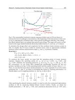
Simulation re
s
s
discussed previ
o
vide timel
y
an
d
s
tem. The actual
s
tin
g
, it can be sp
e
r all simulations
,
d 50 Hz, and ass
u
n
nected to the
n
rameters fixed a
sis of compariso
n
a
nt under anti-
w
o
ws the small
s
n
nected. In bot
h
n
troller, being r
e
p
erational cases.
T
i
vin
g
the process
g
. 10. Small-step
s
e o
f
one unit in
o
s
ults
ousl
y
, the role o
f
d
accurate sup
p
form of the pow
e
e
cified in terms
o
,
the model is e
x
u
mes a Grid s
y
s
t
n
onlinear model
t K=0.1 and T
i
=
0
n
. Figure 10 sho
w
w
indup PI and n
e
s
tep responses (
0
h
cases, the h
yd
e
spectivel
y
10%
a
T
he undershoot
.
response of the
o
peratio
n
.
f
a h
y
droelectric
p
l
y
of its dema
n
e
r demand is rel
a
o
f step, ramp and
x
pressed in the
p
t
em with infinite
of the h
y
droele
c
0
.12 (as currentl
y
w
s the small step
r
e
ural PDF contro
l
0
.05 p.u.) of the
d
roelectric plant
a
nd 30% faster i
n
is also reduced
i
hydro plant wit
h
station in frequ
e
n
ded power con
t
a
ted to Grid freq
u
random input si
p
er-unit s
y
stem,
n
busbars. The ne
u
c
tric power plan
t
y
implemented i
n
r
esponses (0.05 p
l
lers for one uni
t
power station
w
performs better
n
the one unit o
p
i
n both cases w
h
h
neural PDF an
d
e
nc
y
control mo
d
t
ribution to the
u
enc
y
variation
b
g
nals.
n
ormalized to 3
0
u
ral PDF controll
t
. A PI controll
e
n
practice) is us
e
.u.) of the h
y
dro
e
t
operational. Fi
g
w
hen all six un
with the neur
a
p
erational and si
x
h
en a PDF contr
o
d
PI controllers
f
d
e is to
power
b
ut, for
0
0 MW
er was
e
r with
e
d as a
e
lectric
g
ure 11
its are
a
l PDF
x
units
o
ller is
f
or the
NeuralPDFControlStrategyforaHydroelectricStationSimulator 171
pa
m
o
s
ys
Si
m
co
m
tu
r
fo
r
in
s
n
o
w
i
m
o
bl
o
C
u
fu
n
(le
th
e
m
o
vi
e
pa
o
u
al
g
ch
a
ha
ch
a
Fi
g
rameters of a s
p
o
dels ma
y
be ch
a
s
tem and linear
o
m
ulink
©
power
m
binin
g
the
f
r
bine/
g
enerator
a
r
this stud
y
; the
y
s
tance, there are
o
nlinear no
n
-elas
t
i
thout rate limit
a
o
del can be ad
j
u
s
o
ck has the optio
n
u
stomised Simul
i
n
ctions can be i
n
arnin
g
paramete
r
e
plant and its o
u
o
del to be chan
ge
e
wed and assess
e
rameters. The c
u
u
tput deviatio
n
fr
g
orithm takes ar
o
a
n
g
e) to find th
e
ve been reache
d
a
n
g
e.
g
. 9. Simulink
©
p
o
p
ecific block can
a
n
g
ed. These m
o
o
r nonlinear beh
a
plant model. T
h
f
our sub-s
y
ste
m
a
nd sensor filter
s
y
can be select
e
three models
a
t
ic and nonlinear
a
tion and satura
t
s
ted to represen
t
n
of classical and
i
nk
©
S-functions
n
corporated wit
h
r
s) and sample ti
u
tput is the con
t
e
d easil
y
or the
c
e
d. The neural al
u
rrent criterion
o
om the set-point
;
o
und 10 iteratio
n
e
“best” ran
g
e
o
d
the parameter
s
o
wer plant mode
l
be ad
j
usted. For
o
dels can represe
n
a
viour ma
y
be sel
h
e full h
y
droel
e
m
s: Guide va
n
s
. Each block is
p
e
d to represent
a
a
vailable to sim
u
elastic. The
g
uid
e
t
ion. The sensor
t
different condi
t
advanced contr
o
were develope
d
h
i
n
Simulink
©
m
o
me. Its inputs ar
e
t
rol si
g
nal. The
v
c
ontrol al
g
orith
m
g
orithm calculat
e
o
f optimalit
y
is
q
;
however this cr
i
n
s (the exact val
u
o
f parameter val
u
s
sta
y
constant
u
l
.
example, the o
p
n
t the power pl
a
e
cted. Fi
g
ure 9 s
h
e
ctric station m
o
n
e d
y
namics,
p
art of the Simu
l
a
diversit
y
of m
o
u
late the h
y
drau
e
vane d
y
namics
filters block is
a
ions of the natio
o
llers.
d
for the neural
P
o
dels. The neur
a
e
the reference a
n
v
ersatilit
y
of Sim
u
m
to be modifie
d
e
s the optimal v
a
q
uadratic error,
i
terion can be ch
a
u
e depending o
n
u
es (trainin
g
ti
m
u
ntil the set-poi
n
p
eratin
g
point of
a
nt as a SISO or
M
h
ows a schemati
c
o
del is construc
t
h
y
draulic subs
y
l
ink
©
librar
y
dev
e
o
des of operati
o
lic subs
y
stem -
can be selected
w
a
fixed block. T
h
nal
g
rid. The
g
o
v
P
DF al
g
orithms.
a
l PDF block ac
c
n
d the output si
gn
u
link
©
allows th
e
d
and new result
s
a
lues of the cont
r
where the error
a
n
g
ed if necessa
r
n
the ma
g
nitude
m
e). When these
r
n
t or the plant
linear
M
IMO
c
of the
t
ed by
y
stem,
e
loped
o
n. For
linear,
w
ith or
h
e
g
rid
v
ernor
These
c
epts η
n
als of
e
plant
s
to be
r
ol law
is the
ry
. The
of the
r
an
g
es
model
6.
A
s
pr
o
s
ys
te
s
Fo
an
co
n
pa
ba
pl
a
sh
o
co
n
co
n
o
p
dr
i
Fi
g
ca
s
Simulation re
s
s
discussed previ
o
vide timel
y
an
d
s
tem. The actual
s
tin
g
, it can be sp
e
r all simulations
,
d 50 Hz, and ass
u
n
nected to the
n
rameters fixed a
sis of compariso
n
a
nt under anti-
w
o
ws the small
s
n
nected. In bot
h
n
troller, being r
e
p
erational cases.
T
i
vin
g
the process
g
. 10. Small-step
s
e o
f
one unit in
o
s
ults
ousl
y
, the role o
f
d
accurate sup
p
form of the pow
e
e
cified in terms
o
,
the model is e
x
u
mes a Grid s
y
s
t
n
onlinear model
t K=0.1 and T
i
=
0
n
. Figure 10 sho
w
w
indup PI and n
e
s
tep responses (
0
h
cases, the h
yd
e
spectivel
y
10%
a
T
he undershoot
.
response of the
o
peratio
n
.
f
a h
y
droelectric
p
l
y
of its dema
n
e
r demand is rel
a
o
f step, ramp and
x
pressed in the
p
t
em with infinite
of the h
y
droele
c
0
.12 (as currentl
y
w
s the small step
r
e
ural PDF contro
l
0
.05 p.u.) of the
d
roelectric plant
a
nd 30% faster i
n
is also reduced
i
hydro plant wit
h
station in frequ
e
n
ded power con
t
a
ted to Grid freq
u
random input si
p
er-unit s
y
stem,
n
busbars. The ne
u
c
tric power plan
t
y
implemented i
n
r
esponses (0.05 p
l
lers for one uni
t
power station
w
performs better
n
the one unit o
p
i
n both cases w
h
h
neural PDF an
d
e
nc
y
control mo
d
t
ribution to the
u
enc
y
variation
b
g
nals.
n
ormalized to 3
0
u
ral PDF controll
t
. A PI controll
e
n
practice) is us
e
.u.) of the h
y
dro
e
t
operational. Fi
g
w
hen all six un
with the neur
a
p
erational and si
x
h
en a PDF contr
o
d
PI controllers
f
d
e is to
power
b
ut, for
0
0 MW
er was
e
r with
e
d as a
e
lectric
g
ure 11
its are
a
l PDF
x
units
o
ller is
f
or the
AUTOMATION&CONTROL-TheoryandPractice172
Fi
g
ca
s
Fi
g
w
i
re
s
pe
fa
s
P
D
T
o
t=
3
th
e
an
g
. 11. Small-step
s
e o
f
six units in
o
g
ure 12 shows t
h
i
ndup PI and ne
u
s
ponses (0.35 p.
u
rformance is be
t
s
ter in, respectiv
e
D
F controller red
u
o
evaluate the cr
3
00 to units 2-6
a
e
neural PDF res
p
d a hi
g
her unde
r
response of the
o
peratio
n
.
h
e lar
g
e ramp re
s
u
ral PDF controll
e
u
.) of the power
s
t
ter usin
g
the n
e
e
ly, the one unit
u
ces the undersh
o
oss couplin
g
int
e
a
nd the perturba
p
onse has a hi
gh
r
shoot.
hydro plant wit
h
s
ponses (0.35 p.
u
e
rs for one unit
o
s
tation when six
e
ural PDF contr
o
operational and
o
ot.
e
raction a 0.8 p.
tion of unit 1 o
b
h
er overshoot, th
e
h
neural PDF an
d
u
.) of the h
y
dro
e
o
perational. Fi
g
u
r
units are gener
a
o
ller, the respon
s
d
six units opera
t
u. step was ap
p
b
served. Fi
g
ure 1
4
e
PI response ha
s
d
PI controllers
f
e
lectric plant wit
h
r
e 13 shows lar
ge
a
tin
g
. In both cas
s
e being 15% a
n
t
ional cases. Aga
p
lied simultaneo
u
4
shows that, al
t
s
a lon
g
er settli
n
f
or the
h
anti-
e
ramp
es, the
n
d 13%
in, the
u
sl
y
at
t
hou
g
h
ng
time
Fi
g
o
n
Fi
g
si
x
g
. 12. The lar
g
e r
a
n
e unit in operati
o
g
. 13. The lar
g
e r
a
x
units in operati
o
a
mp response of
on
.
a
mp response of
on
.
the hydro plant
w
the hydro plant
w
w
ith neural PDF
w
ith neural PDF
and PI controlle
r
and PI controlle
r
r
s with
r
s with
NeuralPDFControlStrategyforaHydroelectricStationSimulator 173
Fi
g
ca
s
Fi
g
w
i
re
s
pe
fa
s
P
D
T
o
t=
3
th
e
an
g
. 11. Small-step
s
e o
f
six units in
o
g
ure 12 shows t
h
i
ndup PI and ne
u
s
ponses (0.35 p.
u
rformance is be
t
s
ter i
n
, respectiv
e
D
F controller red
u
o
evaluate the cr
3
00 to units 2-6
a
e
neural PDF res
p
d a hi
g
her unde
r
response of the
o
peratio
n
.
h
e lar
g
e ramp re
s
u
ral PDF controll
e
u
.) of the power
s
t
ter usin
g
the n
e
e
l
y
, the one unit
u
ces the undersh
o
oss couplin
g
int
e
a
nd the perturba
p
onse has a hi
gh
r
shoot.
hydro plant wit
h
s
ponses (0.35 p.
u
e
rs for one unit
o
s
tation when six
e
ural PDF contr
o
operational an
d
o
ot.
e
raction a 0.8 p.
tion of unit 1 o
b
h
er overshoot, th
e
h
neural PDF an
d
u
.) of the h
y
dro
e
o
perational. Fi
g
u
r
units are gener
a
o
ller, the respon
s
d
six units opera
t
u. step was ap
p
b
served. Fi
g
ure 1
4
e
PI response ha
s
d
PI controllers
f
e
lectric plant wit
h
r
e 13 shows lar
ge
a
tin
g
. In both cas
s
e being 15% a
n
t
ional cases. A
g
a
p
lied simultaneo
u
4
shows that, al
t
s
a lon
g
er settli
n
f
or the
h
anti-
e
ramp
es, the
n
d 13%
in, the
u
sl
y
at
t
hou
g
h
ng
time
Fi
g
o
n
Fi
g
si
x
g
. 12. The lar
g
e r
a
n
e unit in operati
o
g
. 13. The lar
g
e r
a
x
units in operati
o
a
mp response of
on
.
a
mp response of
on
.
the hydro plant
w
the hydro plant
w
w
ith neural PDF
w
ith neural PDF
and PI controlle
r
and PI controlle
r
r
s with
r
s with
AUTOMATION&CONTROL-TheoryandPractice174
Fi
g
7.
In
th
e
pl
a
o
p
in
c
n
o
th
e
an
T
h
st
o
st
e
ta
k
be
e
in
fu
t
8.
T
h
g
. 14. The cross c
o
Conclusions
this chapter a s
o
e
performance o
a
tform has been
i
p
en architecture
m
c
remental impro
o
nlinear model o
f
e
Dinorwi
g
pow
e
d electrical subs
y
h
e results have s
h
o
ra
g
e station to
i
e
p response of t
h
k
en into account
e
n included in t
h
this application
t
ure work.
Acknowledg
m
h
e authors wish t
o
o
uplin
g
respons
e
o
ftware tool that
f different contr
i
mportant to gra
d
m
akes possible t
h
vement of the
c
f
pumped stora
ge
e
r plant. The mo
d
y
stems and conta
i
h
own how the
n
i
mprove its d
y
n
a
h
e s
y
stem with n
to represent clo
s
h
e nonlinear mo
d
and encourage
u
m
ents
o
thank First H
yd
e
of the h
y
dro pla
models a h
y
dr
o
ollers has been
d
ually increasin
g
h
e rapid inclusio
n
c
ontrol approac
h
e
stations has be
e
d
el includes rep
r
in
s the principal
f
n
eural PDF can
b
a
mic response. I
n
eural PDF is im
p
s
el
y
the real pla
n
d
el. These are pro
m
u
s to address th
e
d
ro Compan
y
for
n
t with PI and n
e
o
power plant an
d
described. The
m
g
the complexity
n
of other contro
h
es and models
e
n discussed. Thi
s
r
esentation of th
e
f
eatures of the p
l
b
e applied to a
h
n
particular, it h
a
p
roved. Multiva
r
n
t. The coupling
b
m
isin
g
results fo
r
e
issue of robust
n
their assistance.
e
ural PDF contro
l
d
allows compar
i
m
odular nature
o
of the simulatio
n
l methods and a
l
alread
y
include
d
s
model was ap
p
e
g
uide vane, h
yd
l
ant’s d
y
namics.
hy
droelectric pu
a
s been shown t
h
r
iable effects hav
e
b
etween pensto
c
r
the use of neur
a
n
ess of the resp
o
l
lers.
i
son of
o
f this
n
s. The
l
so the
d
. The
p
lied to
d
raulic
mped-
h
at the
e
been
c
ks has
a
l PDF
o
nse in
9. References
Aguado-Behar, A., “Topics on identification and adaptive control” (in Spanish), Book edited
by ICIMAF, La Habana, Cuba. 2000.
Bohn, C. and Atherton, D. P., "An analysis package comparing PID anti-windup strategies",
IEEE Control Systems Magazine, vol. 15, p.p. 34-40. 1995.
Djukanovic, M. B., Calovic, M. S., Vesovic, B. V., and Sobajic, D. J., “Neuro-fuzzy controller
of low head hydropower plants using adaptive-network based fuzzy inference
system”, IEEE Trans. on Energy Conversion , 12, pp. 375-381. 1997.
Garcez, J. N., and Garcez, A. R., “A connectionist approach to hydroturbine speed control
parameters tuning using artificial neural network”, Paper presented at 38th IEEE
Midwest Symposium on Circuits and Systems, pp. 641-644. 1995.
Goodwin, G. C., Graebe, S. F. and Salgado, M. E., "Control system design", Prentice Hall,
USA. 2001.
Gracios, C., Vargas, E. & Diaz-Sanchez A., “Describing an IMS by a FNRTPN definition: a
VHDL Approach”, Elsevier Robotics and Computer-Integrated Manufacturing, 21, pp.
241–247. 2005.
Kang, J. K., Lee, J. T., Kim, Y. M., Kwon, B. H., and Choi, K. S., “Speed controller design for
induction motor drivers using a PDF control and load disturbance observer”, Paper
presented at IEEE IECON, Kobe, Japan, pp. 799-803. 1991.
Kundur, P., Power System Stability and Control, New York, NY: Mc Graw Hill. 1994.
Mansoor, S. P., “Behaviour and Operation of Pumped Storage Hydro Plants”, Bangor, U.K.:
PhD. Thesis University of Wales. 2000.
Mansoor, S. P., Jones, D. I., Bradley, D. A., and Aris, F. C., “Stability of a pumped storage
hydropower station connected to a power system”, Paper presented at IEEE Power
Eng. Soc. Winter Meeting, New York, USA, pp. 646-650. 1999.
Mansoor, S. P., Jones, D. I., Bradley, D. A., Aris, F. C., and Jones, G. R., “Reproducing
oscillatory behaviour of a hydroelectric power station by computer simulation”,
Control Engineering Practice, 8, pp. 1261-1272. 2000.
Miller T., Sutton S.R. and Werbos P., Neural Networks for Control, Cambridge Massachusetts:
The MIT Press. 1991.
Minsky, M. L., and Papert, S. A., Perceptrons: Introduction to Computational Geometry.
Cambridge, USA: MIT Press. 1988.
Munakata, T., Fundamentals of the New Artificial Intelligence: Neural, Evolutionary, Fuzzy
and More. London, UK: Springer-Verlag. 2008.
Narendra, K. S., and Mukhopadhyay, S. “Adaptive control using neural networks and
approximate models”, Paper presented at American Control Conference, Seattle, USA,
pp. 355-359. 1996.
Peng, Y., Vrancic, D. and Hanus, R., "Anti-windup, bumpless, and conditioned transfer
techniques for PID controllers", IEEE Control Systems Magazine, vol. 16, p.p. 48-57.
1996.
Rumelhart, D. E., McClelland, J. L., and Group, T. P., Parallel distributed processing:
Explorations in the microstructure of cognition (Vol. 1). Cambridge, USA: MIT
Press.1986.
Shu-Qing, W., Zhao-Hui, L., Zhi-Huai, X., and Zi-Peng, Z. “Application of GA-FNN hybrid
control system for hydroelectric generating units”, Paper presented at International
Conference on Machine Learning and Cybernetics 2, pp. 840-845. 2005.
NeuralPDFControlStrategyforaHydroelectricStationSimulator 175
Fi
g
7.
In
th
e
pl
a
o
p
in
c
n
o
th
e
an
T
h
st
o
st
e
ta
k
be
e
in
fu
t
8.
T
h
g
. 14. The cross c
o
Conclusions
this chapter a s
o
e
performance o
a
tform has been
i
p
en architecture
m
c
remental impro
o
nlinear model o
f
e
Dinorwi
g
pow
e
d electrical subs
y
h
e results have s
h
o
ra
g
e station to
i
e
p response of t
h
k
en into account
e
n included in t
h
this application
t
ure work.
Acknowledg
m
h
e authors wish t
o
o
uplin
g
respons
e
o
ftware tool that
f different contr
i
mportant to
g
ra
d
m
akes possible t
h
vement of the
c
f
pumped stora
ge
e
r plant. The mo
d
y
stems and conta
i
h
own how the
n
i
mprove its d
y
n
a
h
e s
y
stem with n
to represent clo
s
h
e nonlinear mo
d
and encoura
g
e
u
m
ents
o
thank First H
yd
e
of the h
y
dro pla
models a h
y
dr
o
ollers has been
d
uall
y
increasin
g
h
e rapid inclusio
n
c
ontrol approac
h
e
stations has be
e
d
el includes rep
r
in
s the principal
f
n
eural PDF can
b
a
mic response. I
n
eural PDF is im
p
s
el
y
the real pla
n
d
el. These are pro
m
u
s to address th
e
d
ro Compan
y
for
n
t with PI and n
e
o
power plant an
d
described. The
m
g
the complexit
y
n
of other contro
h
es and models
e
n discussed. Thi
s
r
esentation of th
e
f
eatures of the p
l
b
e applied to a
h
n
particular, it h
a
p
roved. Multiva
r
n
t. The coupling
b
m
isin
g
results fo
r
e
issue of robust
n
their assistance.
e
ural PDF contro
l
d
allows compar
i
m
odular nature
o
of the simulatio
n
l methods and a
l
alread
y
include
d
s
model was ap
p
e
g
uide vane, h
yd
l
ant’s d
y
namics.
hy
droelectric pu
a
s been shown t
h
r
iable effects hav
e
b
etween pensto
c
r
the use of neur
a
n
ess of the resp
o
l
lers.
i
son of
o
f this
n
s. The
l
so the
d
. The
p
lied to
d
raulic
mped-
h
at the
e
been
c
ks has
a
l PDF
o
nse in
9. References
Aguado-Behar, A., “Topics on identification and adaptive control” (in Spanish), Book edited
by ICIMAF, La Habana, Cuba. 2000.
Bohn, C. and Atherton, D. P., "An analysis package comparing PID anti-windup strategies",
IEEE Control Systems Magazine, vol. 15, p.p. 34-40. 1995.
Djukanovic, M. B., Calovic, M. S., Vesovic, B. V., and Sobajic, D. J., “Neuro-fuzzy controller
of low head hydropower plants using adaptive-network based fuzzy inference
system”, IEEE Trans. on Energy Conversion , 12, pp. 375-381. 1997.
Garcez, J. N., and Garcez, A. R., “A connectionist approach to hydroturbine speed control
parameters tuning using artificial neural network”, Paper presented at 38th IEEE
Midwest Symposium on Circuits and Systems, pp. 641-644. 1995.
Goodwin, G. C., Graebe, S. F. and Salgado, M. E., "Control system design", Prentice Hall,
USA. 2001.
Gracios, C., Vargas, E. & Diaz-Sanchez A., “Describing an IMS by a FNRTPN definition: a
VHDL Approach”, Elsevier Robotics and Computer-Integrated Manufacturing, 21, pp.
241–247. 2005.
Kang, J. K., Lee, J. T., Kim, Y. M., Kwon, B. H., and Choi, K. S., “Speed controller design for
induction motor drivers using a PDF control and load disturbance observer”, Paper
presented at IEEE IECON, Kobe, Japan, pp. 799-803. 1991.
Kundur, P., Power System Stability and Control, New York, NY: Mc Graw Hill. 1994.
Mansoor, S. P., “Behaviour and Operation of Pumped Storage Hydro Plants”, Bangor, U.K.:
PhD. Thesis University of Wales. 2000.
Mansoor, S. P., Jones, D. I., Bradley, D. A., and Aris, F. C., “Stability of a pumped storage
hydropower station connected to a power system”, Paper presented at IEEE Power
Eng. Soc. Winter Meeting, New York, USA, pp. 646-650. 1999.
Mansoor, S. P., Jones, D. I., Bradley, D. A., Aris, F. C., and Jones, G. R., “Reproducing
oscillatory behaviour of a hydroelectric power station by computer simulation”,
Control Engineering Practice, 8, pp. 1261-1272. 2000.
Miller T., Sutton S.R. and Werbos P., Neural Networks for Control, Cambridge Massachusetts:
The MIT Press. 1991.
Minsky, M. L., and Papert, S. A., Perceptrons: Introduction to Computational Geometry.
Cambridge, USA: MIT Press. 1988.
Munakata, T., Fundamentals of the New Artificial Intelligence: Neural, Evolutionary, Fuzzy
and More. London, UK: Springer-Verlag. 2008.
Narendra, K. S., and Mukhopadhyay, S. “Adaptive control using neural networks and
approximate models”, Paper presented at American Control Conference, Seattle, USA,
pp. 355-359. 1996.
Peng, Y., Vrancic, D. and Hanus, R., "Anti-windup, bumpless, and conditioned transfer
techniques for PID controllers", IEEE Control Systems Magazine, vol. 16, p.p. 48-57.
1996.
Rumelhart, D. E., McClelland, J. L., and Group, T. P., Parallel distributed processing:
Explorations in the microstructure of cognition (Vol. 1). Cambridge, USA: MIT
Press.1986.
Shu-Qing, W., Zhao-Hui, L., Zhi-Huai, X., and Zi-Peng, Z. “Application of GA-FNN hybrid
control system for hydroelectric generating units”, Paper presented at International
Conference on Machine Learning and Cybernetics 2, pp. 840-845. 2005.
AUTOMATION&CONTROL-TheoryandPractice176
Werbos, P. J., Beyond regression: New Tools for Prediction and Analysis in the Behavioral
Sciences, Cambridge, USA: PhD. Thesis Harvard University. 1974.
Widrow, B., and Hoff, M. E., “Adaptive switching circuits”, Paper presented at IRE
WESCON Convention Record 4, pp. 96-104. 1960.
Working group on prime mover energy supply, I, “Hydraulic turbine and turbine control
model for system dynamic studies”, IEEE Trans.s on Power Systems , 7, 167-179.
1992.
Wright, R. M., "Understanding modern generator control", IEEE Transactions on Energy
Conversion, vol. 4, p.p. 453-458. 1989.
Yin-Song, W., Guo-Cai, S., & Ong-Xiang, “The PID-type fuzzy neural network control and
it's application in the hydraulic turbine generators”, Paper presented at Power
Engineering Society meeting. 1, pp. 338-343. 2000.
IntelligentNetworkSystemforProcessControl:Applications,Challenges,Approaches 177
IntelligentNetworkSystemforProcessControl:Applications,Challenges,
Approaches
QurbanAMemon
X
Intelligent Network System for Process Control:
Applications, Challenges, Approaches
Qurban A Memon,
UAE University,
United Arab Emirates
1. Introduction
The ever increasing size, sophistication and complexity of sorting and handling systems, as
industries strive to increase efficiency and offer greater consumer choice, is a constant
problem for system controllers and integrators who build such systems. In particular, the
growing trend towards larger capacity systems, which increase throughput rates and
provide greater flexibility to deal with product variation and changing supply demand,
place increased pressure on system controllers to get things right on time and within
budget, often in the face of loose specifications resulting in large and complex programs. In
view of these demands it comes as no surprise that, when designing and integrating a
control scheme, control engineers prefer to use past practice to minimize risk. Current
practice includes distributed and modular systems like programmable logic controllers
(PLC’s) to break down complex control.
The need for modularity, real timeliness, integrated diagnostics, decentralized control,
expanding physical setups, and functionality has resulted into various types of distributed
control system (DCS). Presently, the DCS concept is not only applied to the process control
and manufacturing automation but it has targeted many areas like communications
engineering (Yang, 2006), physics and nuclear science (Cavineto et al., 2006; Kleines et al.,
2004), power system engineering (Stewart, et al., 2003; Ioannides, 2004), a lighting system
design (Alonso, et al., 2000) etc. The innovative ideas are being applied in field, for example
in (Alonso, et al., 2000), the authors have made use of the power line as the communication
medium for developing the DCS of the lighting system, based on a custom built large scale
integrated Neuron chip incorporating both the control and communication features in a
three microprocessors based system. Another domain of application is industrial plant
automation to reduce operational cost, reduce product development time to market and
improve flexibility of the plant in manufacturing a range of products. The decentralization
in the control systems has brought communication and coordination amongst various sub-
control systems to surface as an important aspect in building an optimal control system
design. The research and development in the area of DCS network design is quite active
because of developments in the communications and information technology field. As an
example, the authors in (O’Hearn et al., 2002) discuss an approach for combination of
11
AUTOMATION&CONTROL-TheoryandPractice178
distributed control system with motor control center involving a number of remote terminal
units within an industrial facility.
The chapter is organized as follows: In the next section, literature review of related work is
presented to highlight existing approaches related to distributed process control and
corresponding applications. The customary environment is discussed in detail along with
performance specification. Additionally, a set of relevant standards are highlighted that set
the direction for common approach using distributed control. In section 3, a set of
approaches are described that maximize the performance of the central process controller.
The section 4 presents recent advancements in communications and information technology
that are proving to be better candidates to yield improved performance for process control.
A set of approaches are described, which minimizes the communication delay, improve
performance, project reconfigurability and interoperability amongst various process devices.
The section 5 provides recent standardization efforts in this area. In section 6, conclusions
are presented followed by references in section 7.
2. Process Control
The DCS consists of a network of small, compact and intelligent nodes placed throughout
the environment and linked via a network to main process controller. Identical hardware
simplifies installation and field replacement. The nodes interface with and control a variety
of device types, while main controller oversees the operation. In DCS, multipoint and
network based process control has replaced the traditional point-to-point architecture which
had been used by the industry for decades. The new architecture has smaller volume of
wiring and distributed processing resulting into quick and easy maintenance and low cost.
These developments have initiated research in two main directions: (i) Network design,
configuration and communication protocols for distributed process control (ii) DCS system
hardware and software architectures. To abreast our selves of first direction of research, a
research work in (Lian et al, 2001) is studied that carries out simulation and experimental
evaluation of three commonly used control networks in the industry. The control networks
evaluated were: Ethernet, ControlNet, and DeviceNet. The evaluation procedure considered
how each control network is used as a communication backbone for a network controlled
system connecting sensors, actuators, and controllers with a detailed discussion on how
medium access control (MAC) protocol works for each network. The performance
parameters addressed include access delay, transmission time, message delay, message
collisions, message throughput, packet size, network utilization, and determinism
boundaries. Timings analysis of each control network presented addresses blocking time,
frame time and propagation time. Using some case studies, the authors concluded that
DeviceNet outperforms the other two networks in case of shorter or prioritized messages,
where as ControlNet is suitable in case of time critical and non-time-critical messages.
Summarily, this research work provided insight in setting performance limits offered by
respective networks.
The Profibus is the standard protocol for communication which is vendor independent so
that the communication between devices from different manufacturers can be implemented
without any special interface adjustment. Regarding the Profibus networks, a
comprehensive study has been carried out in (Tovar & Francisco, 1999), where authors
discuss how Profibus fieldbus networks can be used to support real time communication for
industrial systems. The major contribution noted in this research is that the real time
behavior is guaranteed even in the absence of synchronous bandwidth allocation. The
proposed approaches are based on an assumption based on which real time traffic is
guaranteed. The author in (Hong, 2000) has performed experimental evaluation of Profibus-
FMS. In this work the experimental model of a Profibus-based industrial application is
developed. The experimental environment consists of devices connected in a Profibus
network involving data exchange through the services provided by FMS. The model
evaluates the delay characteristics of a message once it passes through FMS service. Based
on the experimental results, the author suggests an optimal value of target token rotation
and an appropriate segment size to reduce the delay due to variable messages and in
domain management service of FMS respectively. This also concludes that Profibus-FMS
service is greatly affected by conventional values of target rotation time and segment size.
Apart from consideration of network protocols or control networks with associated delay
characteristics, a study has been carried out in (Lian et al, 2002) about the design
considerations for a specific network like DCS. This research work highlights the impact of
network architecture in Network Control System (NCS) class of DCS. Design considerations
include network parameters, control parameters, and network controlled system
performance. The main evaluation measures for the network quality of service (QoS) are:
time delay statistics, network efficiency, network utilization, and the number of lost or
unsent messages. The authors have used a simulation model and an experimental study to
validate the performance characteristics shown by theoretical analysis. Based on results, the
authors demonstrate that the performance characteristics are useful guidelines to choose the
network and control parameters while designing an NCS. The authors suggest that the
performance characteristics are dependent upon the sampling period. However, choosing a
sampling period has not been addressed in the research.
The wireless Profibus integrating wireless and wired devices is also investigated for process
control applications. A study has been carried out in (Willig, 2003), where the parameters of
wireless Profibus protocol standard have been discussed. The author introduces two
approaches to wireless Profibus and compares them with respect to real time performance
in the presence of transmission errors. The work demonstrates that the performance of real
time Profibus protocol in IEEE 802.11 type PHY environment or in presence of bursty errors
is unsatisfactory. The author suggests a specifically tailored protocol for wireless stations in
a situation where integration of wired and wireless stations is necessary in a common
Profibus Local Area Network (LAN). The tailored protocol works on top of IEEE 802.11
PHY and offers the same link layer interface to upper layers as does the Profibus protocol.
The author has shown that round robin protocol with three add-ons namely simple data
relaying, simple poll relaying, and priority restriction outperforms Profibus protocol under
bursty conditions, and a stable ring. However, it was also concluded that keeping logical
ring stable in presence of transmission errors is difficult to achieve. In a similar effort using
network based control, the authors (Almeida, et al., 2002) highlight the importance of
operational flexibility as well as event and time triggered paradigms in fieldbus
communication systems, and propose a protocol to support time-triggered communication
in a flexible way. The authors also discuss an efficient combination of event and time-
triggered traffic with temporal isolation, maintaining the desired properties of both types of
the traffic.
IntelligentNetworkSystemforProcessControl:Applications,Challenges,Approaches 179
distributed control system with motor control center involving a number of remote terminal
units within an industrial facility.
The chapter is organized as follows: In the next section, literature review of related work is
presented to highlight existing approaches related to distributed process control and
corresponding applications. The customary environment is discussed in detail along with
performance specification. Additionally, a set of relevant standards are highlighted that set
the direction for common approach using distributed control. In section 3, a set of
approaches are described that maximize the performance of the central process controller.
The section 4 presents recent advancements in communications and information technology
that are proving to be better candidates to yield improved performance for process control.
A set of approaches are described, which minimizes the communication delay, improve
performance, project reconfigurability and interoperability amongst various process devices.
The section 5 provides recent standardization efforts in this area. In section 6, conclusions
are presented followed by references in section 7.
2. Process Control
The DCS consists of a network of small, compact and intelligent nodes placed throughout
the environment and linked via a network to main process controller. Identical hardware
simplifies installation and field replacement. The nodes interface with and control a variety
of device types, while main controller oversees the operation. In DCS, multipoint and
network based process control has replaced the traditional point-to-point architecture which
had been used by the industry for decades. The new architecture has smaller volume of
wiring and distributed processing resulting into quick and easy maintenance and low cost.
These developments have initiated research in two main directions: (i) Network design,
configuration and communication protocols for distributed process control (ii) DCS system
hardware and software architectures. To abreast our selves of first direction of research, a
research work in (Lian et al, 2001) is studied that carries out simulation and experimental
evaluation of three commonly used control networks in the industry. The control networks
evaluated were: Ethernet, ControlNet, and DeviceNet. The evaluation procedure considered
how each control network is used as a communication backbone for a network controlled
system connecting sensors, actuators, and controllers with a detailed discussion on how
medium access control (MAC) protocol works for each network. The performance
parameters addressed include access delay, transmission time, message delay, message
collisions, message throughput, packet size, network utilization, and determinism
boundaries. Timings analysis of each control network presented addresses blocking time,
frame time and propagation time. Using some case studies, the authors concluded that
DeviceNet outperforms the other two networks in case of shorter or prioritized messages,
where as ControlNet is suitable in case of time critical and non-time-critical messages.
Summarily, this research work provided insight in setting performance limits offered by
respective networks.
The Profibus is the standard protocol for communication which is vendor independent so
that the communication between devices from different manufacturers can be implemented
without any special interface adjustment. Regarding the Profibus networks, a
comprehensive study has been carried out in (Tovar & Francisco, 1999), where authors
discuss how Profibus fieldbus networks can be used to support real time communication for
industrial systems. The major contribution noted in this research is that the real time
behavior is guaranteed even in the absence of synchronous bandwidth allocation. The
proposed approaches are based on an assumption based on which real time traffic is
guaranteed. The author in (Hong, 2000) has performed experimental evaluation of Profibus-
FMS. In this work the experimental model of a Profibus-based industrial application is
developed. The experimental environment consists of devices connected in a Profibus
network involving data exchange through the services provided by FMS. The model
evaluates the delay characteristics of a message once it passes through FMS service. Based
on the experimental results, the author suggests an optimal value of target token rotation
and an appropriate segment size to reduce the delay due to variable messages and in
domain management service of FMS respectively. This also concludes that Profibus-FMS
service is greatly affected by conventional values of target rotation time and segment size.
Apart from consideration of network protocols or control networks with associated delay
characteristics, a study has been carried out in (Lian et al, 2002) about the design
considerations for a specific network like DCS. This research work highlights the impact of
network architecture in Network Control System (NCS) class of DCS. Design considerations
include network parameters, control parameters, and network controlled system
performance. The main evaluation measures for the network quality of service (QoS) are:
time delay statistics, network efficiency, network utilization, and the number of lost or
unsent messages. The authors have used a simulation model and an experimental study to
validate the performance characteristics shown by theoretical analysis. Based on results, the
authors demonstrate that the performance characteristics are useful guidelines to choose the
network and control parameters while designing an NCS. The authors suggest that the
performance characteristics are dependent upon the sampling period. However, choosing a
sampling period has not been addressed in the research.
The wireless Profibus integrating wireless and wired devices is also investigated for process
control applications. A study has been carried out in (Willig, 2003), where the parameters of
wireless Profibus protocol standard have been discussed. The author introduces two
approaches to wireless Profibus and compares them with respect to real time performance
in the presence of transmission errors. The work demonstrates that the performance of real
time Profibus protocol in IEEE 802.11 type PHY environment or in presence of bursty errors
is unsatisfactory. The author suggests a specifically tailored protocol for wireless stations in
a situation where integration of wired and wireless stations is necessary in a common
Profibus Local Area Network (LAN). The tailored protocol works on top of IEEE 802.11
PHY and offers the same link layer interface to upper layers as does the Profibus protocol.
The author has shown that round robin protocol with three add-ons namely simple data
relaying, simple poll relaying, and priority restriction outperforms Profibus protocol under
bursty conditions, and a stable ring. However, it was also concluded that keeping logical
ring stable in presence of transmission errors is difficult to achieve. In a similar effort using
network based control, the authors (Almeida, et al., 2002) highlight the importance of
operational flexibility as well as event and time triggered paradigms in fieldbus
communication systems, and propose a protocol to support time-triggered communication
in a flexible way. The authors also discuss an efficient combination of event and time-
triggered traffic with temporal isolation, maintaining the desired properties of both types of
the traffic.
AUTOMATION&CONTROL-TheoryandPractice180
Other than the domain discussed above, there exists a set of approaches to the same
problem. In one of the approaches, the distributed real time control application
development for task allocation in heterogeneous systems is also reported in (Prayati et al.,
2004), where authors address real time requirements in presence of interoperability of
networked devices. The approach uses functional block allocation (FBALL) algorithm
(International Electrotechnical Commission, 2007) to guarantee real time requirements.
However, this work does not consider network situation during re-configurability of the
process itself or its field devices during real time. Motivated by advent of pervasing
communication and computing, the authors in (Recht & D’Andrea, 2004) consider spatially
interconnected distributed systems with arbitrary discrete symmetry groups to discuss
distributed controller design applicable to a much larger class of structure topologies. In
another approach, the application domains and tasks faced by multi-robot systems of
increasing complexity have been investigated. The authors (Farinelli et al., 2004) describe
various forms of cooperation and coordination realized in the domain of multi-robot
systems.
Although the literature was surveyed at length and considerable approaches were found
related to network based control but the ones addressed in previous section are the most
notable among many others. The issues addressed in literature cover network
considerations (i.e., protocol change or delay characteristics), interoperability of devices;
customization and reconfiguration of the control system. The approaches that address the
network environment analyzed timing characteristics or protocols in order to reduce
communication delays at various stages of information processing.
The process under our consideration is customary i.e., it comprises devices and nodes that
are practically available today and mostly used. The environment can be visualized as
shown in Figure 1. In this Figure, the controller is the main device for which distributed
control environment is to be investigated. The complete system involves interconnection of
control devices, some distributed field and intelligent devices connected to Profibus, and
few intelligent control devices operating under legacy environment. The control devices at
lower level of the system may involve standard PLCs for motion control of a typical drive,
for example. The intelligent devices are normally needed for a specific application where
some of the decisions and local information gathering is done at that level and for onward
transmission to the main controller for final network control decision. The devices are
assumed to be reprogrammable and reconfigurable to suit changing needs of the process
control. The interface shown in the Figure 1 is for legacy intelligence devices which are now
part of the main distributed control system. The network considered is typical with Profibus
compatible network devices with wired or wireless connectivity to a remote device or a
process controller. The PC shown is for management purpose, especially for SCADA
system. All the field devices considered are IEC 61804 compliant, and PLCs are IEC 61131
compliant. Based on our discussion above, the requirements for DCS development for this
process control include consideration of reconfigurability and intelligence in the form of
framework within a Profibus compatible network.
(Motion control through PLC)Controller
Profibus-enabled
device
Profibus-enabled
device
Profibus-enabled
device
Distributed field device
Distributed intelligent devices
Distributed tagged devices
Interface
Drive
PC (for SCADA)
Distributed intelligent devices
Fig. 1. Typical Process Control Network
For comparative purposes, we need to create a model that sets a baseline for performance.
As the configuration of the network is distributed over a wide area, hence we consider a
multiple input multiple output (MIMO) baseline that requires performance, which matches
to that of the centralized MIMO (without network induced delays). A discrete time, causal
and linear time-invariant systems with n states and m outputs can be described as (Goodwin
et al., 2001):
C X (k) (1)
where X, D, K, E, R, N are states of actual MIMO system in centralized control, disturbance,
closed loop controller, error, reference, and sensor noise respectively. It should be noted that
the MIMO system is assumed to be well designed meaning that its performance is
exponentially stable (Goodwin et al., 2001), and that any MIMO control design technique
can be used to develop an appropriate controller K. The parameters A, B, C are minimal
realizations of the actual plant (Goodwin et al., 2001). Using equation (1), various states of
the system can also be calculated:
where A’, B’, C’ represent minimal realizations of the model. For Figure 1 (as a distributed
implementation of MIMO) to achieve same performance to that of the centralized MIMO,
each error or reconfiguration request needs to be communicated over the network at any
sample time, and that there are no communication delays. In order to categorize time delay
d(t) in the network is divided into three categories:
IntelligentNetworkSystemforProcessControl:Applications,Challenges,Approaches 181
Other than the domain discussed above, there exists a set of approaches to the same
problem. In one of the approaches, the distributed real time control application
development for task allocation in heterogeneous systems is also reported in (Prayati et al.,
2004), where authors address real time requirements in presence of interoperability of
networked devices. The approach uses functional block allocation (FBALL) algorithm
(International Electrotechnical Commission, 2007) to guarantee real time requirements.
However, this work does not consider network situation during re-configurability of the
process itself or its field devices during real time. Motivated by advent of pervasing
communication and computing, the authors in (Recht & D’Andrea, 2004) consider spatially
interconnected distributed systems with arbitrary discrete symmetry groups to discuss
distributed controller design applicable to a much larger class of structure topologies. In
another approach, the application domains and tasks faced by multi-robot systems of
increasing complexity have been investigated. The authors (Farinelli et al., 2004) describe
various forms of cooperation and coordination realized in the domain of multi-robot
systems.
Although the literature was surveyed at length and considerable approaches were found
related to network based control but the ones addressed in previous section are the most
notable among many others. The issues addressed in literature cover network
considerations (i.e., protocol change or delay characteristics), interoperability of devices;
customization and reconfiguration of the control system. The approaches that address the
network environment analyzed timing characteristics or protocols in order to reduce
communication delays at various stages of information processing.
The process under our consideration is customary i.e., it comprises devices and nodes that
are practically available today and mostly used. The environment can be visualized as
shown in Figure 1. In this Figure, the controller is the main device for which distributed
control environment is to be investigated. The complete system involves interconnection of
control devices, some distributed field and intelligent devices connected to Profibus, and
few intelligent control devices operating under legacy environment. The control devices at
lower level of the system may involve standard PLCs for motion control of a typical drive,
for example. The intelligent devices are normally needed for a specific application where
some of the decisions and local information gathering is done at that level and for onward
transmission to the main controller for final network control decision. The devices are
assumed to be reprogrammable and reconfigurable to suit changing needs of the process
control. The interface shown in the Figure 1 is for legacy intelligence devices which are now
part of the main distributed control system. The network considered is typical with Profibus
compatible network devices with wired or wireless connectivity to a remote device or a
process controller. The PC shown is for management purpose, especially for SCADA
system. All the field devices considered are IEC 61804 compliant, and PLCs are IEC 61131
compliant. Based on our discussion above, the requirements for DCS development for this
process control include consideration of reconfigurability and intelligence in the form of
framework within a Profibus compatible network.
(Motion control through PLC)Controller
Profibus-enabled
device
Profibus-enabled
device
Profibus-enabled
device
Distributed field device
Distributed intelligent devices
Distributed tagged devices
Interface
Drive
PC (for SCADA)
Distributed intelligent devices
Fig. 1. Typical Process Control Network
For comparative purposes, we need to create a model that sets a baseline for performance.
As the configuration of the network is distributed over a wide area, hence we consider a
multiple input multiple output (MIMO) baseline that requires performance, which matches
to that of the centralized MIMO (without network induced delays). A discrete time, causal
and linear time-invariant systems with n states and m outputs can be described as (Goodwin
et al., 2001):
C X (k) (1)
where X, D, K, E, R, N are states of actual MIMO system in centralized control, disturbance,
closed loop controller, error, reference, and sensor noise respectively. It should be noted that
the MIMO system is assumed to be well designed meaning that its performance is
exponentially stable (Goodwin et al., 2001), and that any MIMO control design technique
can be used to develop an appropriate controller K. The parameters A, B, C are minimal
realizations of the actual plant (Goodwin et al., 2001). Using equation (1), various states of
the system can also be calculated:
where A’, B’, C’ represent minimal realizations of the model. For Figure 1 (as a distributed
implementation of MIMO) to achieve same performance to that of the centralized MIMO,
each error or reconfiguration request needs to be communicated over the network at any
sample time, and that there are no communication delays. In order to categorize time delay
d(t) in the network is divided into three categories:
AUTOMATION&CONTROL-TheoryandPractice182
Thus, the total time delay d(t) is either of the time delays, depending on the prevailing
situation in the environment. The d
1
corresponds to a normal situation (Green level), when
only one field device communicates with the central process controller for a possible update
or reconfiguration at any time. The d
2
corresponds to a situation (Yellow level), when more
than one device (with number set as a threshold) communicate with central process
controller for possible problem getting out of hand. The d
3
corresponds to a situation (Red
level), when a set of devices (with number set as a threshold) tries to communicate with the
central process controller. One obvious direction could be to minimize the delays described
in equation (3) to optimize the performance to match a centralized MIMO system with no
communication delays.
Since filed devices may include nodes or sensors that are non-stationary, protocol invariant
and reconfigurable, the performance requirements stated by centralized MIMO would
require approaches those are not based on legacy network control but should include recent
advancements in sensor, information and communication technologies to match optimized
performance. The combination of distributed control up to edges of the process containing
sensors and tags, with recent information technology concepts like layered software and
agents is an active area of research these days.
2.1 Relevant Standardization
The PLCs are the most widely used processing units and fieldbus is most widely used to
interconnect the process controllers, sensors and actuators in a DCS system. The Profibus is
the standard protocol for communication which is vendor independent so that the
communication between devices from different manufacturers can be implemented without
any special interface adjustment. To realize the plug and play type of operation, the DCS
vendors ought to adopt certain standards both for PLCs and the communication. The
International Electrotechnical Commission (IEC) and PLC manufacturing companies are
actively involved in this development and establishment of standards (International
Electrotechnical Commission, 2007). These standards define basic concepts for the design of
modular, reusable, distributed components for the distributed control systems. Some of the
most popular IEC standards are IEC 61131, IEC 61499 and IEC 61804. Because of the
importance of these standards a brief introduction is presented in the next section.
IEC 61804: This standard addresses the need of common device description for representing
the particular features of the field devices used in the DCS system. The standard is
applicable to Function Blocks (FB) for process control and specifies the Electronic Device
Description Language (EDDL) thus improving the device interoperability.
IEC 61131: This standard has different versions ranging from 61131-1 to 61131-8. The whole
range covers general information about just the PLCs, the equipment requirement and tests,
defines syntax and semantics of programming languages including the function block (FB)
portion of standard for PLC languages, and sets the standards for the communication. To
conclude IEC 61131 was first attempt to provide common terminology and reference model
about hardware (HW) and software (SW) architectures, communication, and languages for a
special class of control devices i.e., the PLCs.
IEC 61193-2: This standard IEC applies to the inspection of electronic components,
packages, and modules for use in electronic and electric equipment, manufactured under
suitable process control, which prevents the outflow of nonconforming products. The
objective is to provide a method for stabilizing, monitoring, and improving processes.
IEC 61987-1: It defines a generic structure in which product features of industrial- process
measurement and control equipment with analogue or digital output should be arranged, in
order to facilitate the understanding of product descriptions when they are transferred from
one party to another. It applies to the production of catalogues of process measuring
equipment supplied by the manufacturer of the product and helps the user to formulate
requirements.
IEC 61499: This standard defines a generic architecture and presents guidelines for the use
of function blocks as the main building block for industrial process measurement and
control system applications. It extends the FB language (defined in IEC 61131-3) to more
adequately meet the requirements of the distributed control in a format that is independent
of implementation. The architecture is presented in terms of implement-able reference
models, textual syntax and graphical representations. The standard addresses the need for
modular software that can be used for distributed industrial process control by defining the
basic concepts for the design of modular, reusable, distributed components for industrial
control systems. It also specifies the software tool requirements.
A variety of fieldbus technologies and digital fieldbus devices have been introduced within
the process industries over the last fifteen years. There has been a gradual acceptance of the
fact that a variety of communication technologies are needed to fully address the application
requirements of a manufacturing facility. Process control systems that use fieldbus, function
blocks, and device descriptive languages already exist in the market. It is clear that the
majority of these systems will continue to use function blocks into the foreseeable future, as
they are modular and reusable. The function blocks hide the changing details and thus
provide a stable interface for the application developers.
3. Sensors and Tagging Technology for Automation
The RFID (Radio Frequency Identification) technology enables events that are in line with
the vision of pervasive computing: using digital media to augment physical and social
spaces rather than replacing them with disembodied virtual spaces. The diversification of
consumer needs has made RFID and other sensor systems an important means within the
manufacturing industry to achieve more efficient multi-product production. Within the
RFID tag process, for example, control functions may be stored and updated as the product
progresses through various stages of the operation. Specific uses of the data within the tag
for process control include part routing, program operations, build orders, component
needs and specific operations which may by unique to only a few products. While operating
in a process control function, the RFID tag can also be used as a portable data base
providing station to station data transfers, repair information, operation status, operation
values, pass/fail data, host data transfers, part history and raw SPC data. One of the major
advantages of using an RFID system in manufacturing is a major reduction in the size and
complexity of the PC or PLC program reducing the cost associated with programming and
also reduces the scan time of the controller.
The object’s RFID tag may be integrated with a large object database to integrate object
community into the space where social interaction occurs (Konomi et al., 2006). The
Researchers at the University of Washington are curious to see what effects RFID technology
IntelligentNetworkSystemforProcessControl:Applications,Challenges,Approaches 183
Thus, the total time delay d(t) is either of the time delays, depending on the prevailing
situation in the environment. The d
1
corresponds to a normal situation (Green level), when
only one field device communicates with the central process controller for a possible update
or reconfiguration at any time. The d
2
corresponds to a situation (Yellow level), when more
than one device (with number set as a threshold) communicate with central process
controller for possible problem getting out of hand. The d
3
corresponds to a situation (Red
level), when a set of devices (with number set as a threshold) tries to communicate with the
central process controller. One obvious direction could be to minimize the delays described
in equation (3) to optimize the performance to match a centralized MIMO system with no
communication delays.
Since filed devices may include nodes or sensors that are non-stationary, protocol invariant
and reconfigurable, the performance requirements stated by centralized MIMO would
require approaches those are not based on legacy network control but should include recent
advancements in sensor, information and communication technologies to match optimized
performance. The combination of distributed control up to edges of the process containing
sensors and tags, with recent information technology concepts like layered software and
agents is an active area of research these days.
2.1 Relevant Standardization
The PLCs are the most widely used processing units and fieldbus is most widely used to
interconnect the process controllers, sensors and actuators in a DCS system. The Profibus is
the standard protocol for communication which is vendor independent so that the
communication between devices from different manufacturers can be implemented without
any special interface adjustment. To realize the plug and play type of operation, the DCS
vendors ought to adopt certain standards both for PLCs and the communication. The
International Electrotechnical Commission (IEC) and PLC manufacturing companies are
actively involved in this development and establishment of standards (International
Electrotechnical Commission, 2007). These standards define basic concepts for the design of
modular, reusable, distributed components for the distributed control systems. Some of the
most popular IEC standards are IEC 61131, IEC 61499 and IEC 61804. Because of the
importance of these standards a brief introduction is presented in the next section.
IEC 61804: This standard addresses the need of common device description for representing
the particular features of the field devices used in the DCS system. The standard is
applicable to Function Blocks (FB) for process control and specifies the Electronic Device
Description Language (EDDL) thus improving the device interoperability.
IEC 61131: This standard has different versions ranging from 61131-1 to 61131-8. The whole
range covers general information about just the PLCs, the equipment requirement and tests,
defines syntax and semantics of programming languages including the function block (FB)
portion of standard for PLC languages, and sets the standards for the communication. To
conclude IEC 61131 was first attempt to provide common terminology and reference model
about hardware (HW) and software (SW) architectures, communication, and languages for a
special class of control devices i.e., the PLCs.
IEC 61193-2: This standard IEC applies to the inspection of electronic components,
packages, and modules for use in electronic and electric equipment, manufactured under
suitable process control, which prevents the outflow of nonconforming products. The
objective is to provide a method for stabilizing, monitoring, and improving processes.
IEC 61987-1: It defines a generic structure in which product features of industrial- process
measurement and control equipment with analogue or digital output should be arranged, in
order to facilitate the understanding of product descriptions when they are transferred from
one party to another. It applies to the production of catalogues of process measuring
equipment supplied by the manufacturer of the product and helps the user to formulate
requirements.
IEC 61499: This standard defines a generic architecture and presents guidelines for the use
of function blocks as the main building block for industrial process measurement and
control system applications. It extends the FB language (defined in IEC 61131-3) to more
adequately meet the requirements of the distributed control in a format that is independent
of implementation. The architecture is presented in terms of implement-able reference
models, textual syntax and graphical representations. The standard addresses the need for
modular software that can be used for distributed industrial process control by defining the
basic concepts for the design of modular, reusable, distributed components for industrial
control systems. It also specifies the software tool requirements.
A variety of fieldbus technologies and digital fieldbus devices have been introduced within
the process industries over the last fifteen years. There has been a gradual acceptance of the
fact that a variety of communication technologies are needed to fully address the application
requirements of a manufacturing facility. Process control systems that use fieldbus, function
blocks, and device descriptive languages already exist in the market. It is clear that the
majority of these systems will continue to use function blocks into the foreseeable future, as
they are modular and reusable. The function blocks hide the changing details and thus
provide a stable interface for the application developers.
3. Sensors and Tagging Technology for Automation
The RFID (Radio Frequency Identification) technology enables events that are in line with
the vision of pervasive computing: using digital media to augment physical and social
spaces rather than replacing them with disembodied virtual spaces. The diversification of
consumer needs has made RFID and other sensor systems an important means within the
manufacturing industry to achieve more efficient multi-product production. Within the
RFID tag process, for example, control functions may be stored and updated as the product
progresses through various stages of the operation. Specific uses of the data within the tag
for process control include part routing, program operations, build orders, component
needs and specific operations which may by unique to only a few products. While operating
in a process control function, the RFID tag can also be used as a portable data base
providing station to station data transfers, repair information, operation status, operation
values, pass/fail data, host data transfers, part history and raw SPC data. One of the major
advantages of using an RFID system in manufacturing is a major reduction in the size and
complexity of the PC or PLC program reducing the cost associated with programming and
also reduces the scan time of the controller.
The object’s RFID tag may be integrated with a large object database to integrate object
community into the space where social interaction occurs (Konomi et al., 2006). The
Researchers at the University of Washington are curious to see what effects RFID technology
AUTOMATION&CONTROL-TheoryandPractice184
could have on social networking (The RFID Ecosystem, University of Washington, 2008). To
see what happens when the tags become ubiquitous, they installed two hundred antennae
in and around a campus building and gave tags to twelve researchers. The result was such
that their every move is recorded by computer. The system responds to nearby participants
and uses algorithms to dynamically derive interconnected social clusters from a publication
database - highlighting new opportunities and key design challenges. The Department of
Computer Science and Engineering at the University of Washington has initiated a large
scale RFID Ecosystem project to investigate user-centered RFID systems in connection with
technology, business, and society and determine balance between privacy and utility (The
RFID Ecosystem, University of Washington, 2008).
For vast field deployment, the authors (Bohn & Mattern, 2004) discuss distribution schemes
where passive RFID tags are deployed in vast quantities and in random fashion. The
authors suggest that certain deployment patterns help create novel RFID based services and
applications. The density, structure of tag distributions, tag typing and clustering is also
investigated by authors. For distributed business like process applications, the author
(Palmer, 2007) discusses effective ways handling vast volume of RFID data for enterprise
application management in real time. The steps applied together help enterprise manage
volumes of raw RFID data in real time, provide reliability and accurate decisions to tackle
the challenges, and exploit opportunities offered by RFID.
It is impossible to separate RFID technology from its issues and concerns surrounding its
deployment, especially with respect to its potential for privacy infringement and identity
theft. The RFID systems are designed to be asymmetric: tags are cheap and require low
power while readers are expensive and power hungry. The various types and functionalities
of these devices have been defined in an RFID class structure by the Auto-ID center, and
later through Electronic Product Code (EPC) global (The EPC Global Standard, 2009), which
has been subsequently refined and built-on. The number and use of standards within RFID
and its associated industries is quite complex, involves a large number of bodies (ISO
standard, 2009; ETSI standard, 2009; RFID Journal, 2009) and are in a continuous process of
development. The various standards produced cover four key areas of RFID technology: its
air interface (tag-reader communications) standards, data content and encoding,
conformance and interoperability between different applications and RFID systems (RFID
Journal, 2009). The various technological issues including its frequency range, standards,
adoption and innovation has also been addressed at length in (Ward et al., 2006).
The RFID’s have also been investigated in conjunction with software technology to optimize
its usability. Integrating software agents into RFID architectures to accumulate information
from tags and process them for specific use at different layers of the control plane has
attracted many operational managers to investigate their deployment for real time use in
industrial applications. The authors in (Naby & Giorgini, 2006) propose a possible
integration between a Multi Agent framework and an RFID based application (back end).
This is enabled by creating an agent for each person to develop its profile and correlating it
with RFID tags movement inside a working environment. The accumulated information,
after processing may be used to facilitate a concurrent mission. The RFID has also been
explored for product identification in agent-based control applications to gain full control
over all products and resources at shop floor level - aiming at installing a completely
distributed agent-based production control system with full information control (Bratukhin
& Treytl, 2006). The summary of literature survey for RFID deployment suggests
investigating a multi-agent architecture as an application layer within existing RFID layered
architecture that includes tag layer, RFID-reader layer, and back-end layer (Naby &
Giorgini, 2006).
4. Agents for Intelligent Control
Recently there have been a number of advances in distributed artificial intelligence that
provide the tools to move away from the traditional centralized, scan based programmable
logic control (PLC) architecture towards a new architecture for the real-time distributed
intelligent control. The Industrial control is typically implemented using large and often
expensive hardware platforms that support monolithic computer control applications. The
authors in (Bernnan et al., 2002) propose a general approach for dynamic and intelligent
reconfiguration of real-time distributed control systems that utilizes the IEC 61499 function
block model (International Electrotechnical Commission, 2007) to achieve shorter up-front
commissioning time and significantly more responsive to changes, and is based on object
oriented and agent based methods. Similarly, the authors in (Heck et al., 2003) discuss
software technology for implementing reusable, distributed control components to make
corresponding systems more flexible and dynamically re-configurable, so that they can be
adapted in an easy way. Intelligent control and management of traffic and transportation
systems in connected environments has been investigated in (Wang, 2005) that requires
agent based technology to develop cheap, reliable and flexible control system. The authors
in (Maturana et al., 2005) present distributive intelligent control architecture using agents by
developing tools and methodologies for agent based solutions to a wide variety of
industrial, financial and security problems, as classical control does not adapt dynamically
well to the variability of the process. In another work, the authors in (Fregene et al., 2005)
present a systems-and-control-oriented intelligent agent framework, as well as its
composition into specific kinds of multi-agent systems to achieve the coordinated control of
multiple multimode dynamical systems. The author in (Vyatkin, 2008) discusses distributed
intelligent control using IEC 61499 (International Electrotechnical Commission, 2007)
programming architecture for distributed automation systems in reconfigurable
manufacturing systems. The testing environment consists of a network of identical software
components for control of baggage handling system at the airport. The work in (Gingko
Networks, 2008) provides simple decentralized ways to deal with a growing number of
modern network requirements, by using distributed intelligent agents to deal with local
situations in a more responsive way like sensing and observing events and changes
occurring locally. In order to understand the potential use of agents in process industry, a
survey has been presented in (Yang & Vyatkin, 2008) on design and validation of
distributed control in process industry. The respective authors discuss distributed control
benefits such as flexibility, reconfigurability and software reusability. The process control
system is generally considered as a hybrid system as it usually contains both discrete and
continuous dynamics. The authors highlight the importance of hybrid verification and
simulation while handling validation of distributed systems.
In intelligent control design, scalability of a control system, active system reconfiguration,
distributed intelligence and reduced communications are targeted benefits. In these
situations, the issues like customization, decentralization and modularity at various levels of
control are the main challenges in respective DCS design to facilitate distributed field
IntelligentNetworkSystemforProcessControl:Applications,Challenges,Approaches 185
could have on social networking (The RFID Ecosystem, University of Washington, 2008). To
see what happens when the tags become ubiquitous, they installed two hundred antennae
in and around a campus building and gave tags to twelve researchers. The result was such
that their every move is recorded by computer. The system responds to nearby participants
and uses algorithms to dynamically derive interconnected social clusters from a publication
database - highlighting new opportunities and key design challenges. The Department of
Computer Science and Engineering at the University of Washington has initiated a large
scale RFID Ecosystem project to investigate user-centered RFID systems in connection with
technology, business, and society and determine balance between privacy and utility (The
RFID Ecosystem, University of Washington, 2008).
For vast field deployment, the authors (Bohn & Mattern, 2004) discuss distribution schemes
where passive RFID tags are deployed in vast quantities and in random fashion. The
authors suggest that certain deployment patterns help create novel RFID based services and
applications. The density, structure of tag distributions, tag typing and clustering is also
investigated by authors. For distributed business like process applications, the author
(Palmer, 2007) discusses effective ways handling vast volume of RFID data for enterprise
application management in real time. The steps applied together help enterprise manage
volumes of raw RFID data in real time, provide reliability and accurate decisions to tackle
the challenges, and exploit opportunities offered by RFID.
It is impossible to separate RFID technology from its issues and concerns surrounding its
deployment, especially with respect to its potential for privacy infringement and identity
theft. The RFID systems are designed to be asymmetric: tags are cheap and require low
power while readers are expensive and power hungry. The various types and functionalities
of these devices have been defined in an RFID class structure by the Auto-ID center, and
later through Electronic Product Code (EPC) global (The EPC Global Standard, 2009), which
has been subsequently refined and built-on. The number and use of standards within RFID
and its associated industries is quite complex, involves a large number of bodies (ISO
standard, 2009; ETSI standard, 2009; RFID Journal, 2009) and are in a continuous process of
development. The various standards produced cover four key areas of RFID technology: its
air interface (tag-reader communications) standards, data content and encoding,
conformance and interoperability between different applications and RFID systems (RFID
Journal, 2009). The various technological issues including its frequency range, standards,
adoption and innovation has also been addressed at length in (Ward et al., 2006).
The RFID’s have also been investigated in conjunction with software technology to optimize
its usability. Integrating software agents into RFID architectures to accumulate information
from tags and process them for specific use at different layers of the control plane has
attracted many operational managers to investigate their deployment for real time use in
industrial applications. The authors in (Naby & Giorgini, 2006) propose a possible
integration between a Multi Agent framework and an RFID based application (back end).
This is enabled by creating an agent for each person to develop its profile and correlating it
with RFID tags movement inside a working environment. The accumulated information,
after processing may be used to facilitate a concurrent mission. The RFID has also been
explored for product identification in agent-based control applications to gain full control
over all products and resources at shop floor level - aiming at installing a completely
distributed agent-based production control system with full information control (Bratukhin
& Treytl, 2006). The summary of literature survey for RFID deployment suggests
investigating a multi-agent architecture as an application layer within existing RFID layered
architecture that includes tag layer, RFID-reader layer, and back-end layer (Naby &
Giorgini, 2006).
4. Agents for Intelligent Control
Recently there have been a number of advances in distributed artificial intelligence that
provide the tools to move away from the traditional centralized, scan based programmable
logic control (PLC) architecture towards a new architecture for the real-time distributed
intelligent control. The Industrial control is typically implemented using large and often
expensive hardware platforms that support monolithic computer control applications. The
authors in (Bernnan et al., 2002) propose a general approach for dynamic and intelligent
reconfiguration of real-time distributed control systems that utilizes the IEC 61499 function
block model (International Electrotechnical Commission, 2007) to achieve shorter up-front
commissioning time and significantly more responsive to changes, and is based on object
oriented and agent based methods. Similarly, the authors in (Heck et al., 2003) discuss
software technology for implementing reusable, distributed control components to make
corresponding systems more flexible and dynamically re-configurable, so that they can be
adapted in an easy way. Intelligent control and management of traffic and transportation
systems in connected environments has been investigated in (Wang, 2005) that requires
agent based technology to develop cheap, reliable and flexible control system. The authors
in (Maturana et al., 2005) present distributive intelligent control architecture using agents by
developing tools and methodologies for agent based solutions to a wide variety of
industrial, financial and security problems, as classical control does not adapt dynamically
well to the variability of the process. In another work, the authors in (Fregene et al., 2005)
present a systems-and-control-oriented intelligent agent framework, as well as its
composition into specific kinds of multi-agent systems to achieve the coordinated control of
multiple multimode dynamical systems. The author in (Vyatkin, 2008) discusses distributed
intelligent control using IEC 61499 (International Electrotechnical Commission, 2007)
programming architecture for distributed automation systems in reconfigurable
manufacturing systems. The testing environment consists of a network of identical software
components for control of baggage handling system at the airport. The work in (Gingko
Networks, 2008) provides simple decentralized ways to deal with a growing number of
modern network requirements, by using distributed intelligent agents to deal with local
situations in a more responsive way like sensing and observing events and changes
occurring locally. In order to understand the potential use of agents in process industry, a
survey has been presented in (Yang & Vyatkin, 2008) on design and validation of
distributed control in process industry. The respective authors discuss distributed control
benefits such as flexibility, reconfigurability and software reusability. The process control
system is generally considered as a hybrid system as it usually contains both discrete and
continuous dynamics. The authors highlight the importance of hybrid verification and
simulation while handling validation of distributed systems.
In intelligent control design, scalability of a control system, active system reconfiguration,
distributed intelligence and reduced communications are targeted benefits. In these
situations, the issues like customization, decentralization and modularity at various levels of
control are the main challenges in respective DCS design to facilitate distributed field
AUTOMATION&CONTROL-TheoryandPractice186
operations in a process control. Intelligent network control together with active remote
monitoring of a scalable distributed system has turned out to be an active area of research.
The obvious choice seems to break the complex control process into two distinct processes
(Memon, 2008): Local Process for simple task execution at field device level using social
interaction of field process entities and generating operational parameters at the device
level; Central Process for estimation of new characteristics of social entities only when
entities need to be created or modified during operational stages. The independence at local
process level minimizes communication between devices to avoid bottlenecks arising due to
interoperability of devices, network protocol change or simple operational requirements at
the device level; and provide a degree of re-configurability of field devices at the same time.
Using local intelligence collected through interactions of local entities and combined with
controller requirements at the central level helps solve combinatorial complexity present at
any time during the operation. Thus, two areas are targeted: social interactions of entities
with domain intelligence, and effective decision making set by the central process. The
following is the discussion on both processes.
4.1 Local Process
Knowledge integration at central level requires balanced information from local entities.
These entities tend to be distributed throughout the operational environment to support all
operations. The job of these entities can be done effectively by distributed agents. The agents
collaborate socially, learn and adjust their abilities within the constraints of the global
process. Thus the agents are sophisticated software entities set by central process to execute
trained intelligence at the local level. The functions within this process include: how agents
collaborate and clusters are formed to accumulate intelligence and enable decision making;
how access to another agent is facilitated; and the procedure for inter-cluster collaboration.
To make sure that these agents form an intelligent system, the framework has to conform to
four requirements (Maturana et al., 2005): that the system is decentralized; agents follow
centricity; they use common language; and that the system is scalable.
4.1.1 Agent design & management
The agents deployed in existing infrastructures are designed to be manageable as other
components with tools and procedures already in place at central process level. Each agent
has software components adaptable to environmental changes. Each of these can be
considered as a specialized function with some built-in capabilities, like sensedecideact
loop. The various categories of these specialized functions include:
Producing knowledge in cooperation with other agents
Evaluating the situation and decide to apply an appropriate action individually or
through collaboration
Acting onto the network element parameters, like fine tuning quality of service
Forward useful information to the central process
Agents provide simple decentralized ways to deal with a growing number of modern
process control network requirements. Agents can provide a set of management functions:
Configuration functions for downloading of configuration parameters
Control functions for monitoring the process environment and providing on-line
activation and inspection of agents
Data collection functions for enabling uploading of useful information collected by
agents
Deployment functions enable to add or remove agents dynamically
Agents can also request for additional capabilities once they discover that the task at hand
cannot be fulfilled with existing ones. The programming of these agents is done at the
central level where a set of heuristics is used for reasoning at the local level, and is stored as
a function block diagram (like an internal script). The life cycle of the cluster is pre-set at the
central process during agent design, and which can be re-negotiated upon an agent’s
request. The agents know about their equipment, and continuously monitor their state, as
shown in Figure 2. The Figure 2 shows agents residing on tagged network elements, known
as intelligent devices that can compute and communicate. Based on the intelligence, they
can decide whether to participate in a mission or not, as shown in Figure 3. Thus the design
of an agent is normally made open ended to add flexibility during operation.
4.1.2 Agent Collaboration
Each agent maintains its own view of the environment on the basis of the information
obtained directly from its sensors and indirectly from the network through collaboration
with its neighboring agents. As the local events are known and are properly documented in
its view, the agent responds quickly and appropriately. Based on its view, agent may decide
to automatically adapt its certain parameters of its own network element. The
environmental view of the agent drives implicit cooperation amongst agents. This mode of
cooperation is simple, robust and well situated for dynamically changing environments. The
collaborating agents join (on their own will) and thus form a cluster in order to enable a
decision making. Within their constraints, they accomplish their task. In addition to agents,
there are other computing units that exist at the local level and which help to form a cluster.
These are known as cluster directory (CD) and cluster facilitator (CF) respectively. The
following steps describe the operational scene of agent collaboration in clusters:
Agent N receives a request from central process for a task planning.
It checks its internal scripts, if it can participate then it solves the local steps.
For external steps, it contacts cluster directory to check for other agents if they also
have external capability.
In that case, CD provides contact details.
Upon receipt of these details, agent N creates CF
N
and passes on these details.
CF
N
understands coordination context.
CF
N
passes the request to specified agents, and thus cluster is formed.
For efficient collaboration, CD must remain updated for recording the information of its
members, such as agent name, agent locator, service name, service type, and so on. Upon
joining or leaving the cluster, an agent must register or cancel registration respectively
through CF. Through a query, an agent can find out other members’ services and locators.
Through these steps, a trust is developed amongst agents.
IntelligentNetworkSystemforProcessControl:Applications,Challenges,Approaches 187
operations in a process control. Intelligent network control together with active remote
monitoring of a scalable distributed system has turned out to be an active area of research.
The obvious choice seems to break the complex control process into two distinct processes
(Memon, 2008): Local Process for simple task execution at field device level using social
interaction of field process entities and generating operational parameters at the device
level; Central Process for estimation of new characteristics of social entities only when
entities need to be created or modified during operational stages. The independence at local
process level minimizes communication between devices to avoid bottlenecks arising due to
interoperability of devices, network protocol change or simple operational requirements at
the device level; and provide a degree of re-configurability of field devices at the same time.
Using local intelligence collected through interactions of local entities and combined with
controller requirements at the central level helps solve combinatorial complexity present at
any time during the operation. Thus, two areas are targeted: social interactions of entities
with domain intelligence, and effective decision making set by the central process. The
following is the discussion on both processes.
4.1 Local Process
Knowledge integration at central level requires balanced information from local entities.
These entities tend to be distributed throughout the operational environment to support all
operations. The job of these entities can be done effectively by distributed agents. The agents
collaborate socially, learn and adjust their abilities within the constraints of the global
process. Thus the agents are sophisticated software entities set by central process to execute
trained intelligence at the local level. The functions within this process include: how agents
collaborate and clusters are formed to accumulate intelligence and enable decision making;
how access to another agent is facilitated; and the procedure for inter-cluster collaboration.
To make sure that these agents form an intelligent system, the framework has to conform to
four requirements (Maturana et al., 2005): that the system is decentralized; agents follow
centricity; they use common language; and that the system is scalable.
4.1.1 Agent design & management
The agents deployed in existing infrastructures are designed to be manageable as other
components with tools and procedures already in place at central process level. Each agent
has software components adaptable to environmental changes. Each of these can be
considered as a specialized function with some built-in capabilities, like sensedecideact
loop. The various categories of these specialized functions include:
Producing knowledge in cooperation with other agents
Evaluating the situation and decide to apply an appropriate action individually or
through collaboration
Acting onto the network element parameters, like fine tuning quality of service
Forward useful information to the central process
Agents provide simple decentralized ways to deal with a growing number of modern
process control network requirements. Agents can provide a set of management functions:
Configuration functions for downloading of configuration parameters
Control functions for monitoring the process environment and providing on-line
activation and inspection of agents
Data collection functions for enabling uploading of useful information collected by
agents
Deployment functions enable to add or remove agents dynamically
Agents can also request for additional capabilities once they discover that the task at hand
cannot be fulfilled with existing ones. The programming of these agents is done at the
central level where a set of heuristics is used for reasoning at the local level, and is stored as
a function block diagram (like an internal script). The life cycle of the cluster is pre-set at the
central process during agent design, and which can be re-negotiated upon an agent’s
request. The agents know about their equipment, and continuously monitor their state, as
shown in Figure 2. The Figure 2 shows agents residing on tagged network elements, known
as intelligent devices that can compute and communicate. Based on the intelligence, they
can decide whether to participate in a mission or not, as shown in Figure 3. Thus the design
of an agent is normally made open ended to add flexibility during operation.
4.1.2 Agent Collaboration
Each agent maintains its own view of the environment on the basis of the information
obtained directly from its sensors and indirectly from the network through collaboration
with its neighboring agents. As the local events are known and are properly documented in
its view, the agent responds quickly and appropriately. Based on its view, agent may decide
to automatically adapt its certain parameters of its own network element. The
environmental view of the agent drives implicit cooperation amongst agents. This mode of
cooperation is simple, robust and well situated for dynamically changing environments. The
collaborating agents join (on their own will) and thus form a cluster in order to enable a
decision making. Within their constraints, they accomplish their task. In addition to agents,
there are other computing units that exist at the local level and which help to form a cluster.
These are known as cluster directory (CD) and cluster facilitator (CF) respectively. The
following steps describe the operational scene of agent collaboration in clusters:
Agent N receives a request from central process for a task planning.
It checks its internal scripts, if it can participate then it solves the local steps.
For external steps, it contacts cluster directory to check for other agents if they also
have external capability.
In that case, CD provides contact details.
Upon receipt of these details, agent N creates CF
N
and passes on these details.
CF
N
understands coordination context.
CF
N
passes the request to specified agents, and thus cluster is formed.
For efficient collaboration, CD must remain updated for recording the information of its
members, such as agent name, agent locator, service name, service type, and so on. Upon
joining or leaving the cluster, an agent must register or cancel registration respectively
through CF. Through a query, an agent can find out other members’ services and locators.
Through these steps, a trust is developed amongst agents.
AUTOMATION&CONTROL-TheoryandPractice188
NE
Agent
NE
Agent
NE
Agent
NE
Agent
NE
Agent
NE: Network Element / Device with a tag
- Goals
- Actions
- Domain Knowledge
Agent Process
Agent state
Agent
Sensors
Effectors
Sensor
Initialize (value )
FilterData ( )
AcquireData ( )
Fig. 2. Agents in a process network
CD: Community Directory; CF: Community Facilitator
Cluster 1: Agents (1,2,3,4); Cluster 2: Agents (3,5,6)
Agent
1
Agent
2
Agent
3
CF
1
CF
3
Agent
4
Agent
5
Agent
6
CD
Fig. 3. Agent Collaboration
4.1.3 Agent Technology
Recently developed tools may be used to help design cluster facilitator (CF) and domain
ontology, using for example DARPA Markup Language (DAML) (DAML website, 2000).
The DAML extends XML (Extensible Markup Language) and RDF (Resource Description
Framework) to include domain ontology. It provides rich set of constructs to create ontology
and to markup information for attaining machine readability and understandability; it has
capability of inference so that membership or service of cluster can be precisely defined. In
case of XML and RDF, there seems to be no significant literature to manage ontology, and
this is why, DAML is chosen to build cluster ontology. A number of agent standards have
been in practice like Knowledge Query Manipulation Language (KQML), OMG’s mobile
agent system interoperability facility (MASIF) and the Foundation for Intelligent Physical
Agents (FIPA). The Foundation for Intelligent Physical Agent (FIPA) Agent Management
Specification (FIPA specification, 2002) is extended to develop the agent role called CF to
manage cluster directory (CD) and cluster ontology. Using assistance from DAML-based
ontology, the members of the cluster are able to form cluster and communicate with other
agents. The interaction among domain ontology, CD and CF can be best understood using
Figure 4. The Figure 4 shows how CF gets access to DAML files and facilitates the common
goal of the cluster. There are tools available like Jena semantic web (HP Labs toolkit, 2003)
that can be used to handle the cluster directory (CD) built using DAML, and to develop a
Java class “Directory”.
CF
Domain
Ontology
Cluster
Directory
Cluster Ontology
}
DAML File(s)
File access
Fig. 4. Linking CF with DAML
From discussions above, the main functions of CD can be summarized, as:
Add and Remove the information of an agent
Get the list of agent names of all members
Get the information of individual agent by name
Get ontology used by members in the cluster
Add external ontology if provided by an agent
Using local process mechanism and main functions of CD, the partial directory can be
described as shown in Figure 5. It shows information of CF (lines 1-9) and members of
cluster (lines 20-22), the cluster directory also records meta-data about cluster such as cluster
name (line 12), cluster description (lines 13-15), ontology used in cluster (lines 16-18), and so
on.
IntelligentNetworkSystemforProcessControl:Applications,Challenges,Approaches 189
NE
Agent
NE
Agent
NE
Agent
NE
Agent
NE
Agent
NE: Network Element / Device with a tag
- Goals
- Actions
- Domain Knowledge
Agent Process
Agent state
Agent
Sensors
Effectors
Sensor
Initialize (value )
FilterData ( )
AcquireData ( )
Fig. 2. Agents in a process network
CD: Community Directory; CF: Community Facilitator
Cluster 1: Agents (1,2,3,4); Cluster 2: Agents (3,5,6)
Agent
1
Agent
2
Agent
3
CF
1
CF
3
Agent
4
Agent
5
Agent
6
CD
Fig. 3. Agent Collaboration
4.1.3 Agent Technology
Recently developed tools may be used to help design cluster facilitator (CF) and domain
ontology, using for example DARPA Markup Language (DAML) (DAML website, 2000).
The DAML extends XML (Extensible Markup Language) and RDF (Resource Description
Framework) to include domain ontology. It provides rich set of constructs to create ontology
and to markup information for attaining machine readability and understandability; it has
capability of inference so that membership or service of cluster can be precisely defined. In
case of XML and RDF, there seems to be no significant literature to manage ontology, and
this is why, DAML is chosen to build cluster ontology. A number of agent standards have
been in practice like Knowledge Query Manipulation Language (KQML), OMG’s mobile
agent system interoperability facility (MASIF) and the Foundation for Intelligent Physical
Agents (FIPA). The Foundation for Intelligent Physical Agent (FIPA) Agent Management
Specification (FIPA specification, 2002) is extended to develop the agent role called CF to
manage cluster directory (CD) and cluster ontology. Using assistance from DAML-based
ontology, the members of the cluster are able to form cluster and communicate with other
agents. The interaction among domain ontology, CD and CF can be best understood using
Figure 4. The Figure 4 shows how CF gets access to DAML files and facilitates the common
goal of the cluster. There are tools available like Jena semantic web (HP Labs toolkit, 2003)
that can be used to handle the cluster directory (CD) built using DAML, and to develop a
Java class “Directory”.
CF
Domain
Ontology
Cluster
Directory
Cluster Ontology
}
DAML File(s)
File access
Fig. 4. Linking CF with DAML
From discussions above, the main functions of CD can be summarized, as:
Add and Remove the information of an agent
Get the list of agent names of all members
Get the information of individual agent by name
Get ontology used by members in the cluster
Add external ontology if provided by an agent
Using local process mechanism and main functions of CD, the partial directory can be
described as shown in Figure 5. It shows information of CF (lines 1-9) and members of
cluster (lines 20-22), the cluster directory also records meta-data about cluster such as cluster
name (line 12), cluster description (lines 13-15), ontology used in cluster (lines 16-18), and so
on.
AUTOMATION&CONTROL-TheoryandPractice190
1. <cluster:CF rdf:ID="theCF">
2. <cluster:agentName>"CF"</cluster:agentName>
3. <cluster:agentDescription>
4. "DCS Cluster Facilitator"
5. </cluster:agentDescription>
6. <cluster:locator>
7. " />8. </cluster:locator>
9. </cluster:CF>
10.
11. <cluster:Cluster rdf:ID="DCSCluster">
12.<cluster:clusterName>"DCS"</cluster:clusterName>
13. <cluster:clusterDescription>
14. "Distributed Control System"
15. </cluster:clusterDescription>
16. <cluster ontology>
17. " />18. </cluster:ontology>
19.
20. <cluster:hasCF rdf:Resource="#theCF"/>
21. <cluster:consistOf rdf:Resource="#agent1"/>
22. <cluster:consistOf rdf:Resource="#agent2"/>
23. </cluster:Cluster>
Fig. 5. DCS Cluster Directory
4.1.4 Example
An example can be illustrated to show how ontology may be updated (Fig. 6(b)) and that
how interactions may develop in a local process. It should be noted here that basic cluster
ontology (the knowledge of the local process) provided by CF remains the same but all
members’ domain knowledge (ontology) may not be the same. For example, user agent
holds basic knowledge of the local process but does not understand the knowledge that a
distributed field device holds. Through DAML-based ontology, members can communicate
with each other to acquire requested service, as shown in Figure 6. It is clear from the Figure
6 that when distributed field device agent joins the cluster, it informs CF about
corresponding ontology it provides (Figure 6(a)). Thus the CF maintains local process
ontology plus the distributed field device ontology. When a user agent wants to perform a
task, it asks CF about domain ontology and the agents that provide external capability. In
response, CF informs the user agent if ontology is to be acquired (Figure 6(c)). Thus, the
user agent can communicate with the distributed field device agent (Figure 6(d)).
DFD agent
CF
DCS ontology
DFD ontology
User
agent
a
b
c
d
> File access
> Agent Communication
DFD : Distributed Field Device
Fig. 6. Update in ontology provided by distributed field device agent
4.2 Central Process
This process handles core mechanism that glues organization’s local processes to the central
process. Some of the functions for example library of agents, their job description, definition
of controller tasks, and domain ontology of each cluster can be defined offline before the
implementation actually starts. The dynamic components are removing of agent deadlocks,
security of agents, estimation of characteristics and relationships and decision making in
cases of emergencies and when situation develops beyond the capabilities of agent clusters.
It seems that all of these dynamic functions together may require computations, but the
advantages gained are many: (i) reduced communications between central process
controller and the device(s) (ii) provide simplicity to enable better interoperability (iii)
intelligence gathering to build a degree of reconfigurability in a case estimated parameters
exceed beyond a limit (iv) reduced human supervision. It can be also argued that
complexity of this process is only a technology mismatch, and that if only small scale
changes are to be decided at the central process like reconfiguration of device parameters,
security of agents, then intelligence can further be distributed to the agents at the local level.
Based on presented work in section 3 and in 4.1, agents can be embedded in tagged devices
within a layered architecture to support business operations and services in real time. In
Figure 7, the model architecture of four tiers is drawn to implement objectives of the central
process. At the bottom layer (Tier 1), active readers or Profibus/Profinet enabled devices
collect data, often collected on a trigger similar to a motion sensor. These readers should be
controlled by one and only one edge server to avoid problems related to network
partitioning. In addition, this layer supports the notion that intelligence be introduced at the
edges to reduce data traffic and improve reaction at the next layer. This layer also provides
hardware abstraction for various Profibus/Profinet compatible hardware and network
drivers for interoperability of devices. The edge sever (Tier 2) regularly poll the readers for
any update from device agents, monitors tagged devices and distributed devices through
readers, performs device management, and updates integration layer. This layer may also
work with system through controls and open source frameworks that provide abstraction
and design layer. The integration layer (Tier 3) provides design and engineering of various
objects needed for central controller as well as for field processes and for simulation levels of
reconfigurability. This layer is close to business application layer (Tier 4). The monitoring of