AUTOMATION & CONTROL - Theory and Practice Part 13 pptx
Bạn đang xem bản rút gọn của tài liệu. Xem và tải ngay bản đầy đủ của tài liệu tại đây (765.68 KB, 25 trang )
ArticialIntelligenceMethodsinFaultTolerantControl 291
MRAC-
Neural
Network-
Abrupt
Fault
- The system is robust against sensor faults
- MSE=0.00030043
- If the fault magnitude is 1 the system
response varies around +/- 3%. This
means that the system is degraded but
still works. This degradation becomes
smaller over time, because the system
continues accommodating the fault.
- MSE=0.13154736
MRAC-
Neural
Network-
Gradual
Fault
- The system is robust against sensor faults.
- MSE=0.00030043
- If the fault saturation is +/- 1 the system
response varies around +3% and - 4%.
This means that the system is degraded
but still works. This degradation becomes
smaller over time, because the system
continues accommodating the fault.
- MSE=0.13149647
Table 1. Results of experiments with abrupt and gradual faults simulated in the 3 different
fault tolerant MRAC schemes.
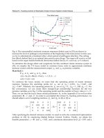
The following graphs represent a comparison between the different simulated experiments.
Figure 18 represents system behavior when abrupt faults are simulated. The three graphs on
the left column are sensor faults and the graphs from the right column are actuator faults.
The sensor faults have a magnitude of 1.8 and the actuator faults a magnitude of 1. It is
observed that the MRAC-Neural Network represents the best scheme because is insensitive
to abrupt sensor faults and has a good performance when abrupt actuator faults are
developed.
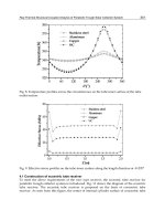
Figure 19 graphs represent system behavior when gradual faults are present on the system.
The fault magnitude of the sensor fault is of 1.8 and the magnitude of the actuator fault is of
1. It can be seen also that the MRAC-Neural Networks Controller scheme is the better option
because is robust to sensor faults and has a less degraded performance in actuator faults. In
conclusion, the proposed MRAC-Neural Network scheme gives the best fault tolerant
control scheme developed in this work.
Fig. 18. Abrupt-Sensor Faults (left column) and Abrupt-Actuator Faults (Right column) of
the three different proposed schemes, the fault started at time 7000 secs.
0 1000 2000 3000 4000 5000 6000 7000 8000 9000 10000
35
35.5
36
36.5
37
37.5
TIME (SECONDS)
TEMPERATURE (ºC)
0 1000 2000 3000 4000 5000 6000 7000 8000 9000 10000
35
35.5
36
36.5
37
37.5
TIME (SECONDS)
TEMPERATURE (ºC)
0 1000 2000 3000 4000 5000 6000 7000 8000 9000 10000
35
35.5
36
36.5
37
37.5
TIME (SECONDS)
TEMPERATURE (ºC)
MRAC
MRAC-Neural Network
MRAC-PID
Adaptation
Mechanism
0 0.2 0.4 0.6 0.8 1 1.2 1.4 1.6 1.8 2
x 10
4
35
35.5
36
36.5
37
37.5
38
TIME (SECONDS)
TEMPERATURE (ºC)
0 0.2 0.4 0.6 0.8 1 1.2 1.4 1.6 1.8 2
x 10
4
35
35.5
36
36.5
37
37.5
38
TEMPERATURE (ºC)
TIME (SECONDS)
0 0.2 0.4 0.6 0.8 1 1.2 1.4 1.6 1.8 2
x 10
4
35
35.5
36
36.5
37
37.5
38
TIME (SECONDS)
TEMPERATURE (ºC)
MRAC-Neural Network
MRAC
MRAC-PID
AUTOMATION&CONTROL-TheoryandPractice292
Fig. 19. Gradual-Sensor Faults (left column) and Gradual-Actuator Faults (Right column) of
the three different proposed schemes, the fault started at time 7000 secs.
0 1000 2000 3000 4000 5000 6000 7000 8000 9000 10000
35
35.5
36
36.5
37
37.5
TIME (SECONDS)
TEMPERATURE (ºC)
0 1000 2000 3000 4000 5000 6000 7000 8000 9000 10000
35
35.5
36
36.5
37
37.5
TIME (SECONDS)
TEMPERATURE (ºC)
0 1000 2000 3000 4000 5000 6000 7000 8000 9000 10000
35
35.5
36
36.5
37
37.5
TEMPERATURE (ºC)
TIME (SECONDS)
Adaptation
Mechanism
MRAC
MRAC-Neural Network
MRAC-PID
0 0.2 0.4 0.6 0.8 1 1.2 1.4 1.6 1.8 2
x 10
4
35
35.5
36
36.5
37
37.5
38
TEMPERATURE (ºC)
TIME (SECONDS)
0 0.2 0.4 0.6 0.8 1 1.2 1.4 1.6 1.8 2
x 10
4
35
35.5
36
36.5
37
37.5
38
TEMPERATURE (ºC)
TIME (SECONDS)
MRAC-PID
MRAC
0 0.2 0.4 0.6 0.8 1 1.2 1.4 1.6 1.8 2
x 10
4
35
35.5
36
36.5
37
37.5
38
TIME (SECONDS)
TEMPERATURE (ºC)
MRAC-Neural Network
5. References
Ballé, P.; Fischera, M.; Fussel, D.; Nells, O. & Isermann, R. (1998). Integrated control,
diagnosis and reconfiguration of a heat exchanger.
IEEE Control Systems Magazine,
Vol. 18, No. 3, (June 1998) 52–63, ISSN: 0272-1708.
Bastani, F., & Chen, I. (1988). The role of artificial intelligence in fault-tolerant process-
control systems.
Proceedings of the 1st international conference on Industrial and
engineering applications of artificial intelligence and expert systems
, pp. 1049-1058,
ISBN:0-89791-271-3, June 1988, ACM, Tullahoma, Tennessee, United States.
Blanke, M.; Izadi-Zamanabadi, R.; Bogh, R. & Lunau, Z. P. (1997). Fault tolerant control
systems—A holistic view.
Control Engineering Practice, Vol. 5, No. 5, (May 1997)
693–702, ISSN: S0967-0661(97)00051-8.
Blanke, M., Staroswiecki, M., & Wu, N. E. (2001). Concepts and methods in fault-tolerant
control.
In Proceedings of the 2001 American Control Conference, pp. 2606–2620,
Arlington, Virginia, ISBN: 0-7803-6495-3, June 2001, IEEE, United States.
Blanke, M.; Kinnaert, M.; Lunze, J. & Staroswiecki, M. (2003). Diagnosis and Fault-Tolerant
Control
. Springer-Verlag, ISBN: 3540010564 , Berlin, Germany.
Blondel, V. (1994). Simultaneous Stabilization of Linear Systems. Springer Verlag, ISBN:
3540198628, Heidelberg, Germany.
Caglayan, A.; Allen, S. & Wehmuller, K. (1988). Evaluation of a second generation
reconfiguration strategy for aircraft flight control systems subjected to actuator
failure/surface damage.
Proceedings of the 1988 National Aerospace and Electronics
Conference
, pp. 520–529, May 1988, IEEE, Dayton , Ohio, United States.
Diao, Y. & Passino, K. (2001). Stable fault-tolerant adaptive fuzzy/neural control for turbine
engine.
IEEE Transactions on Control Systems Technology, Vol. 9, No. 3, (May 2001)
494–509, ISSN: 1063-6536.
Diao,Y. & Passino, K. (2002). Intelligent fault-tolerant control using adaptive and learning
methods.
Control Engineering Practice, Vol. 10, N. 8, (August 2002) 801–817, ISSN:
0967-0661.
Eterno, J.; Looze, D; Weiss, J. & Willsky, A. (1985). Design Issues for Fault-Tolerant
Restructurable Aircraft Control,
Proceedings of 24th Conference on Decision and
Control
, pp. 900-905, December 1985, IEEE, Fort Lauderdale, Florida, United States.
Farrell, J.; Berger, T. & Appleby, B. (1993). Using learning techniques to accommodate
unanticipated faults.
IEEE Control Systems Magazine, Vol. 13, No. 3, (June 1993) 40–
49, ISSN: 0272-1708.
Gao, Z. & Antsaklis, P. (1991). Stability of the pseudo-inverse method for reconfigurable
control systems.
International Journal of Control, Vol. 53, No. 3, (March 1991) 717–729.
Goldberg, D. (1989). Genetic algorithms in search, optimization, and machine learning, Addison-
Wesley, ISBN: 0201157675, Reading, Massachusetts, United States.
Gomaa, M. (2004). Fault tolerant control scheme based on multi-ann faulty models.
Electrical, Electronic and Computer Engineering.
ICEEC International Conference,
Vol. , No. , (September 2004) 329 – 332, ISBN: 0-7803-8575-6.
Gurney, K. (1997). An Introduction to Neural Networks, CRC Press Company, ISBN:
1857285034, London, United Kingdom.
Holmes, M. & Ray, A. (2001). Fuzzy damage-mitigating control of a fossil power plant.
IEEE
Transactions on Control Systems Technology
, Vol. 9, No. 1, (January 2001) 140– 147,
ISSN: 1558-0865.
ArticialIntelligenceMethodsinFaultTolerantControl 293
Fig. 19. Gradual-Sensor Faults (left column) and Gradual-Actuator Faults (Right column) of
the three different proposed schemes, the fault started at time 7000 secs.
0 1000 2000 3000 4000 5000 6000 7000 8000 9000 10000
35
35.5
36
36.5
37
37.5
TIME (SECONDS)
TEMPERATURE (ºC)
0 1000 2000 3000 4000 5000 6000 7000 8000 9000 10000
35
35.5
36
36.5
37
37.5
TIME (SECONDS)
TEMPERATURE (ºC)
0 1000 2000 3000 4000 5000 6000 7000 8000 9000 10000
35
35.5
36
36.5
37
37.5
TEMPERATURE (ºC)
TIME (SECONDS)
Adaptation
Mechanism
MRAC
MRAC-Neural Network
MRAC-PID
0 0.2 0.4 0.6 0.8 1 1.2 1.4 1.6 1.8 2
x 10
4
35
35.5
36
36.5
37
37.5
38
TEMPERATURE (ºC)
TIME (SECONDS)
0 0.2 0.4 0.6 0.8 1 1.2 1.4 1.6 1.8 2
x 10
4
35
35.5
36
36.5
37
37.5
38
TEMPERATURE (ºC)
TIME (SECONDS)
MRAC-PID
MRAC
0 0.2 0.4 0.6 0.8 1 1.2 1.4 1.6 1.8 2
x 10
4
35
35.5
36
36.5
37
37.5
38
TIME (SECONDS)
TEMPERATURE (ºC)
MRAC-Neural Network
5. References
Ballé, P.; Fischera, M.; Fussel, D.; Nells, O. & Isermann, R. (1998). Integrated control,
diagnosis and reconfiguration of a heat exchanger.
IEEE Control Systems Magazine,
Vol. 18, No. 3, (June 1998) 52–63, ISSN: 0272-1708.
Bastani, F., & Chen, I. (1988). The role of artificial intelligence in fault-tolerant process-
control systems.
Proceedings of the 1st international conference on Industrial and
engineering applications of artificial intelligence and expert systems
, pp. 1049-1058,
ISBN:0-89791-271-3, June 1988, ACM, Tullahoma, Tennessee, United States.
Blanke, M.; Izadi-Zamanabadi, R.; Bogh, R. & Lunau, Z. P. (1997). Fault tolerant control
systems—A holistic view.
Control Engineering Practice, Vol. 5, No. 5, (May 1997)
693–702, ISSN: S0967-0661(97)00051-8.
Blanke, M., Staroswiecki, M., & Wu, N. E. (2001). Concepts and methods in fault-tolerant
control.
In Proceedings of the 2001 American Control Conference, pp. 2606–2620,
Arlington, Virginia, ISBN: 0-7803-6495-3, June 2001, IEEE, United States.
Blanke, M.; Kinnaert, M.; Lunze, J. & Staroswiecki, M. (2003). Diagnosis and Fault-Tolerant
Control
. Springer-Verlag, ISBN: 3540010564 , Berlin, Germany.
Blondel, V. (1994). Simultaneous Stabilization of Linear Systems. Springer Verlag, ISBN:
3540198628, Heidelberg, Germany.
Caglayan, A.; Allen, S. & Wehmuller, K. (1988). Evaluation of a second generation
reconfiguration strategy for aircraft flight control systems subjected to actuator
failure/surface damage.
Proceedings of the 1988 National Aerospace and Electronics
Conference
, pp. 520–529, May 1988, IEEE, Dayton , Ohio, United States.
Diao, Y. & Passino, K. (2001). Stable fault-tolerant adaptive fuzzy/neural control for turbine
engine.
IEEE Transactions on Control Systems Technology, Vol. 9, No. 3, (May 2001)
494–509, ISSN: 1063-6536.
Diao,Y. & Passino, K. (2002). Intelligent fault-tolerant control using adaptive and learning
methods.
Control Engineering Practice, Vol. 10, N. 8, (August 2002) 801–817, ISSN:
0967-0661.
Eterno, J.; Looze, D; Weiss, J. & Willsky, A. (1985). Design Issues for Fault-Tolerant
Restructurable Aircraft Control,
Proceedings of 24th Conference on Decision and
Control
, pp. 900-905, December 1985, IEEE, Fort Lauderdale, Florida, United States.
Farrell, J.; Berger, T. & Appleby, B. (1993). Using learning techniques to accommodate
unanticipated faults.
IEEE Control Systems Magazine, Vol. 13, No. 3, (June 1993) 40–
49, ISSN: 0272-1708.
Gao, Z. & Antsaklis, P. (1991). Stability of the pseudo-inverse method for reconfigurable
control systems.
International Journal of Control, Vol. 53, No. 3, (March 1991) 717–729.
Goldberg, D. (1989). Genetic algorithms in search, optimization, and machine learning, Addison-
Wesley, ISBN: 0201157675, Reading, Massachusetts, United States.
Gomaa, M. (2004). Fault tolerant control scheme based on multi-ann faulty models.
Electrical, Electronic and Computer Engineering.
ICEEC International Conference,
Vol. , No. , (September 2004) 329 – 332, ISBN: 0-7803-8575-6.
Gurney, K. (1997). An Introduction to Neural Networks, CRC Press Company, ISBN:
1857285034, London, United Kingdom.
Holmes, M. & Ray, A. (2001). Fuzzy damage-mitigating control of a fossil power plant.
IEEE
Transactions on Control Systems Technology
, Vol. 9, No. 1, (January 2001) 140– 147,
ISSN: 1558-0865.
AUTOMATION&CONTROL-TheoryandPractice294
Isermann, R.; Schwarz, R. & Stölzl, S. (2002). Fault-tolerant drive-by-wire systems.
IEEE
Control Systems Magazine, Vol. 22, No. 5, (October 2002) 64-81, ISSN: 0272-1708.
Jaimoukha, I.; Li, Z. & Papakos, V. (2006). A matrix factorization solution to the H-/H
infinity fault detection problem.
Automatica, Vol. 42, No. 11, 1907 – 1912, ISSN: 000-
1098.
Jiang, J. (1994). Design of reconfigurable control systems using eigenstructure assignments.
International Journal of Control, Vol. 59, No. 2, 395–410, ISNN 00-7179.
Karsai, G.; Biswas, G.;Narasimhan, S.; Szemethy, T.; Peceli, G.; Simon, G. & Kovacshazy, T.
(2002). Towards Fault-Adaptive Control of Complex Dynamic Systems, In:
Software- Enabled Control, Tariq Samad and Gary Balas, Wiley-IEEE press, 347-368,
ISBN: 9780471234364, United States.
Kwong,W.; Passino, K.; Laukonen, E. & Yurkovich, S. (1995). Expert supervision of fuzzy
learning systems for fault tolerant aircraft control.
Proceedings of the IEEE, Vol. 83,
No. 3, (March 1995) 466–483, ISSN: 0018-9219.
Liang, B. & Duan, G. (2004). Robust H-infinity fault-tolerant control for uncertain descriptor
systems by dynamical compensators.
Journal of Control Theory and Applications, Vol.
2, No. 3, (August 2004) 288-292, ISSN: 1672-6340.
Lunze, J. & J. H. Richter. (2006). Control reconfiguration: Survey of methods and open problems. ,
ATP, Bochum, Germany.
Mahmoud, M.; Jiang, J. & Zhang, Y. (2003). Active fault tolerant control systems: Stochastic
analysis and synthesis, Springer, ISBN: 2540003185, Berlin, Germany.
Mitchell, M. (1996).
An introduction to genetic algorithms, MIT Press, ISBN: 0262631857,
Cambridge, Massachusetts, United States.
Nagrath, .J (2006).
Control Systems Engineering, Anshan Ltd, ISBN: 1848290039, Indian
Institute of Technology, Delhi, India.
Neimann, H. & Stoustrup, J. (2005), Passive fault tolerant control of a double inverted
pendulum - a case study.
Control Engineering Practice, Vol. 13, No 8, 1047-1059,
ISNN: 0967-0661.
Nguyen, H.; Nadipuren, P.; Walker, C. & Walker, E. (2002).
A First Course in Fuzzy and
Neural Control
, CRC Press Company, ISBN: 158488241, United States.
Oudghiri, M.; Chadli, M. & El Hajjaji, A. (2008). Sensors Active Fault Tolerant Control For
Vehicle Via Bank of Robust H∞ Observers.
17th International Federation of Automatic
Control (IFAC) World Congress
, July 2008, IFAC, Seoul, Korea.
Passino, K. and Yurkovich, S. (1997). Fuzzy Control, Addison-Wesley Longman, ISBN:
020118074, United States.
Pashilkar,A.; Sundararajan, N.; Saratchandran, P. (2006). A Fault-tolerant Neural Aided
Controller for Aircraft Auto-landing.
Aerospace Science and Technology, Vol. 10, pp.
49-61.
Patton, R. J. (1997). Fault-tolerant control: The 1997 situation.
Proceedings of the 3rd IFAC
symposium on fault detection, supervision and safety for technical processes,
pp. 1033–
1055, Hull, United Kingdom.
Patton, R.; Lopez-Toribio, C. & Uppal, F. (1999). Artificial intelligence approaches to fault
diagnosis
. IEEE Condition Monitoring: Machinery, External Structures and Health, I,
pp. 5/1 – 518, April 1999, IEEE, Birmingham, United Kingdom.
Perhinschi, M.; Napolitano, M.; Campa, G., Fravolini, M.; & Seanor, B. (2007). Integration of
Sensor and Actuator Failure Detection, Identification, and Accommodation
Schemes within Fault Tolerant Control Laws.
Control and Intelligent Systems, Vol. 35,
No. 4, 309-318, ISSN: 1480-1752.
Polycarpou, M. & Helmicki, A. (1995). Automated fault detection and accommodation: A
learning systems approach.
IEEE Transactions on Systems, Vol. 25, No. 11,
(November 1995) 1447–1458.
Polycarpou, M. & Vemuri, A. (1995). Learning methodology for failure detection and
accommodation.
IEEE Control Systems Magazine, Vol. 15, No. 3, (June 1995) 16–24,
ISSN: 0272-1708.
Polycarpou, M. (2001). Fault accommodation of a class of multivariable nonlinear dynamical
systems using a learning approach.
IEEE Transactions on Automatic Control, Vol. 46,
No.5, (May 2001) 736–742, ISSN: 0018-9286.
Rumerhart, D.; McClelland, J.; & the PDP Research Group. (1986).
Parallel distributed
processing: explorations in the microstructure of cognition
, MIT Press, ISBN:
0262631105, Cambridge, Massachusetts, United States.
Ruan, D. (1997).
Intelligent Hybrid Systems: Fuzzy Logic, Neural Networks, and Genetic
Algorithms
, Kluwer Academic Publishers, ISBN: 0792399994, United States.
Schroder, P.; Chipperfield, A.; Fleming, P. & Grum, N. (1998). Fault tolerant control of
active magnetic bearings. IEEE International Symposium on Industrial Electronics,
pp. 573-578, ISBN: 0-7803-4756-0, July 1998, IEEE, Pretoria, South Africa.
Skogestad, S., & Postlethwaite I. (2005).
Multivariable Feedback Control-Analysis and Design,
John Wiley & Sons, ISBN: 9780470011676, United States.
Staroswiecki, M. (2005). Fault tolerant control: The pseudo-inverse method revisited.
Proceedings 16th IFAC World Congress, pp. Th-E05-TO/2, IFAC, Prague, Czech
Republic.
Steffen, T. (2005).
Control reconfiguration of dynamic systems: Linear approaches and structural
tests
, Springer, ISBN: 3540257306, Berlin, Germany.
Stengel, R. (1991). Intelligent Failure-Tolerant Control. IEEE Control Systems Magazine, Vol.
11, No. 4, (June 1991) 14-23, ISSN: 0272-1708.
Sugawara, E.; Fukushi, M. & Horiguchi, S. (2003). Fault Tolerant Multi-layer Neural
Networks with GA Training.
The 18th IEEE International Symposium on Defect and
Fault Tolerance in VLSI systems
,pp. 328-335, ISBN: 0-7695-2042-1, IEEE, November
2003 Boston, Massachusetts, United States.
Venkatasubramanian, V.; Rengaswamy, R.; Yin, K. & Kavuri, S. (2003a). A review of process
fault detection and diagnosis. Part I. Quantitative modelbased methods. Computers
and Chemical Engineering
, Vol. 27, No. 3, 293–311, ISSN-0098-1354.
Venkatasubramanian, V.; Rengaswamy, R. & Kavuri, S. (2003b). A review of process fault
detection and diagnosis. Part II. Qualitative models and search strategies.
Computers and Chemical Engineering, Vol. 27, No. 3, 313–326, ISSN: 0098-1354.
Venkatasubramanian, V.; Rengaswamy, R.; Kavuri, S. & Yin, K. (2003c). A review of process
fault detection and diagnosis. Part III. Process history based methods. Computers
and Chemical Engineering
, Vol. 27, No. 3, 327–346, ISSN: 0098-1354.
Wang, H. & Wang, Y. (1999). Neural-network-based fault-tolerant control of unknown
nonlinear systems.
IEE Proceedings—Control Theory and Applications, Vol. 46, No. 5,
(September 1999) 389–398, ISSN; 1350-2379.
ArticialIntelligenceMethodsinFaultTolerantControl 295
Isermann, R.; Schwarz, R. & Stölzl, S. (2002). Fault-tolerant drive-by-wire systems.
IEEE
Control Systems Magazine, Vol. 22, No. 5, (October 2002) 64-81, ISSN: 0272-1708.
Jaimoukha, I.; Li, Z. & Papakos, V. (2006). A matrix factorization solution to the H-/H
infinity fault detection problem.
Automatica, Vol. 42, No. 11, 1907 – 1912, ISSN: 000-
1098.
Jiang, J. (1994). Design of reconfigurable control systems using eigenstructure assignments.
International Journal of Control, Vol. 59, No. 2, 395–410, ISNN 00-7179.
Karsai, G.; Biswas, G.;Narasimhan, S.; Szemethy, T.; Peceli, G.; Simon, G. & Kovacshazy, T.
(2002). Towards Fault-Adaptive Control of Complex Dynamic Systems, In:
Software- Enabled Control, Tariq Samad and Gary Balas, Wiley-IEEE press, 347-368,
ISBN: 9780471234364, United States.
Kwong,W.; Passino, K.; Laukonen, E. & Yurkovich, S. (1995). Expert supervision of fuzzy
learning systems for fault tolerant aircraft control.
Proceedings of the IEEE, Vol. 83,
No. 3, (March 1995) 466–483, ISSN: 0018-9219.
Liang, B. & Duan, G. (2004). Robust H-infinity fault-tolerant control for uncertain descriptor
systems by dynamical compensators.
Journal of Control Theory and Applications, Vol.
2, No. 3, (August 2004) 288-292, ISSN: 1672-6340.
Lunze, J. & J. H. Richter. (2006). Control reconfiguration: Survey of methods and open problems. ,
ATP, Bochum, Germany.
Mahmoud, M.; Jiang, J. & Zhang, Y. (2003). Active fault tolerant control systems: Stochastic
analysis and synthesis, Springer, ISBN: 2540003185, Berlin, Germany.
Mitchell, M. (1996).
An introduction to genetic algorithms, MIT Press, ISBN: 0262631857,
Cambridge, Massachusetts, United States.
Nagrath, .J (2006).
Control Systems Engineering, Anshan Ltd, ISBN: 1848290039, Indian
Institute of Technology, Delhi, India.
Neimann, H. & Stoustrup, J. (2005), Passive fault tolerant control of a double inverted
pendulum - a case study.
Control Engineering Practice, Vol. 13, No 8, 1047-1059,
ISNN: 0967-0661.
Nguyen, H.; Nadipuren, P.; Walker, C. & Walker, E. (2002).
A First Course in Fuzzy and
Neural Control
, CRC Press Company, ISBN: 158488241, United States.
Oudghiri, M.; Chadli, M. & El Hajjaji, A. (2008). Sensors Active Fault Tolerant Control For
Vehicle Via Bank of Robust H∞ Observers.
17th International Federation of Automatic
Control (IFAC) World Congress
, July 2008, IFAC, Seoul, Korea.
Passino, K. and Yurkovich, S. (1997). Fuzzy Control, Addison-Wesley Longman, ISBN:
020118074, United States.
Pashilkar,A.; Sundararajan, N.; Saratchandran, P. (2006). A Fault-tolerant Neural Aided
Controller for Aircraft Auto-landing.
Aerospace Science and Technology, Vol. 10, pp.
49-61.
Patton, R. J. (1997). Fault-tolerant control: The 1997 situation.
Proceedings of the 3rd IFAC
symposium on fault detection, supervision and safety for technical processes,
pp. 1033–
1055, Hull, United Kingdom.
Patton, R.; Lopez-Toribio, C. & Uppal, F. (1999). Artificial intelligence approaches to fault
diagnosis
. IEEE Condition Monitoring: Machinery, External Structures and Health, I,
pp. 5/1 – 518, April 1999, IEEE, Birmingham, United Kingdom.
Perhinschi, M.; Napolitano, M.; Campa, G., Fravolini, M.; & Seanor, B. (2007). Integration of
Sensor and Actuator Failure Detection, Identification, and Accommodation
Schemes within Fault Tolerant Control Laws.
Control and Intelligent Systems, Vol. 35,
No. 4, 309-318, ISSN: 1480-1752.
Polycarpou, M. & Helmicki, A. (1995). Automated fault detection and accommodation: A
learning systems approach.
IEEE Transactions on Systems, Vol. 25, No. 11,
(November 1995) 1447–1458.
Polycarpou, M. & Vemuri, A. (1995). Learning methodology for failure detection and
accommodation.
IEEE Control Systems Magazine, Vol. 15, No. 3, (June 1995) 16–24,
ISSN: 0272-1708.
Polycarpou, M. (2001). Fault accommodation of a class of multivariable nonlinear dynamical
systems using a learning approach.
IEEE Transactions on Automatic Control, Vol. 46,
No.5, (May 2001) 736–742, ISSN: 0018-9286.
Rumerhart, D.; McClelland, J.; & the PDP Research Group. (1986).
Parallel distributed
processing: explorations in the microstructure of cognition
, MIT Press, ISBN:
0262631105, Cambridge, Massachusetts, United States.
Ruan, D. (1997).
Intelligent Hybrid Systems: Fuzzy Logic, Neural Networks, and Genetic
Algorithms
, Kluwer Academic Publishers, ISBN: 0792399994, United States.
Schroder, P.; Chipperfield, A.; Fleming, P. & Grum, N. (1998). Fault tolerant control of
active magnetic bearings. IEEE International Symposium on Industrial Electronics,
pp. 573-578, ISBN: 0-7803-4756-0, July 1998, IEEE, Pretoria, South Africa.
Skogestad, S., & Postlethwaite I. (2005).
Multivariable Feedback Control-Analysis and Design,
John Wiley & Sons, ISBN: 9780470011676, United States.
Staroswiecki, M. (2005). Fault tolerant control: The pseudo-inverse method revisited.
Proceedings 16th IFAC World Congress, pp. Th-E05-TO/2, IFAC, Prague, Czech
Republic.
Steffen, T. (2005).
Control reconfiguration of dynamic systems: Linear approaches and structural
tests
, Springer, ISBN: 3540257306, Berlin, Germany.
Stengel, R. (1991). Intelligent Failure-Tolerant Control. IEEE Control Systems Magazine, Vol.
11, No. 4, (June 1991) 14-23, ISSN: 0272-1708.
Sugawara, E.; Fukushi, M. & Horiguchi, S. (2003). Fault Tolerant Multi-layer Neural
Networks with GA Training.
The 18th IEEE International Symposium on Defect and
Fault Tolerance in VLSI systems
,pp. 328-335, ISBN: 0-7695-2042-1, IEEE, November
2003 Boston, Massachusetts, United States.
Venkatasubramanian, V.; Rengaswamy, R.; Yin, K. & Kavuri, S. (2003a). A review of process
fault detection and diagnosis. Part I. Quantitative modelbased methods. Computers
and Chemical Engineering
, Vol. 27, No. 3, 293–311, ISSN-0098-1354.
Venkatasubramanian, V.; Rengaswamy, R. & Kavuri, S. (2003b). A review of process fault
detection and diagnosis. Part II. Qualitative models and search strategies.
Computers and Chemical Engineering, Vol. 27, No. 3, 313–326, ISSN: 0098-1354.
Venkatasubramanian, V.; Rengaswamy, R.; Kavuri, S. & Yin, K. (2003c). A review of process
fault detection and diagnosis. Part III. Process history based methods. Computers
and Chemical Engineering
, Vol. 27, No. 3, 327–346, ISSN: 0098-1354.
Wang, H. & Wang, Y. (1999). Neural-network-based fault-tolerant control of unknown
nonlinear systems.
IEE Proceedings—Control Theory and Applications, Vol. 46, No. 5,
(September 1999) 389–398, ISSN; 1350-2379.
AUTOMATION&CONTROL-TheoryandPractice296
Yang, G. & Ye, D. (2006). Adaptive fault-tolerant Hinf control via state feedback for linear
systems against actuator faults,
Conference on Decision and Control, pp. 3530-3535,
December 2006, San Diego, California, United States.
Yen, G. & DeLima, P. (2005). An Integrated Fault Tolerant Control Framework Using
Adaptive Critic Design.
International Joint Conference on Neural Networks, Vol. 5, pp.
2983-2988, ISBN: 0-7803-9048-2.
Zhang, D.; Wang Z. & Hu, S. (2007). Robust satisfactory fault-tolerant control of uncertain
linear discrete-time systems: an LMI approach.
International Journal of Systems
Science
, Vol. 38, No. 2, (February 2007) 151-165, ISSN: 0020-7721.
Zhang, Y., & Jiang, J. (2008). Bibliographical review on reconfigurable fault-tolerant control
systems.
Elsevier Annual Reviews in Control, Vol. 32, (March 2008) 229-252.
ARealTimeExpertSystemForDecisionMakinginRotaryRailcarDumpers 297
A Real Time Expert System For Decision Making in Rotary Railcar
Dumpers
OsevaldoFarias,SoaneLabidi,JoãoFonsecaNeto,JoséMouraandSamyAlbuquerque
X
A Real Time Expert System For Decision
Making in Rotary Railcar Dumpers
Osevaldo Farias, Sofiane Labidi, João Fonseca Neto,
José Moura and Samy Albuquerque
Federal University of Maranhão and VALE
Brazil
1. Introduction
In a great deal of industrial production mechanisms approaches able to turn automatic a
wide range of processes have being used. Such applications demand high control pattern,
tolerance to faults, decision taking and many other important factor that make large scale
systems reliable (Su et al., 2005), (Su et al., 2000) and.
In particular, Artificial Intelligence (AI) presents a wide applicability of those approaches
implementing their concepts under the form of Expert Systems (Fonseca Neto et al., 2003).
Applications with this architecture extend knowledge-based systems and allow the machine
to be structured into a model apt to act and behave in the most similar way a human
specialist uses its reasoning when facing a decision taken problem (Feigenbaum, 1992).
The VALE production system comprehends several mining complexes, among which is
notorious the Ponta da Madeira Dock Terminal (PMDT). In this complex macro level
processes of Unloading, Storing and Minerals Shipping are performed, supervised by a very
reliable Operational Control Center (OCC).
This article discusses the development of an on-line expert system applied to decision taken
when facing faults occurred in the VV311-K01 used to unload minerals at the VALE’s
PMDT. This project attends the handling of a large quantity of available operative data
created at production time, and cares of the organization, interpretation and understanding
of these data.
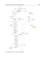
Besides automation technologies, in order to attend our proposal, we apply some
information technologies such as: the JESS, the JAVA language and also XML (eXtensible
Markup Language) aiming the real time running of the Expert System.
This article is organized as follows: Section 2 describes the Expert System proposal; in
Section 3 are described the particularities and the operation of the rotary railcar dumper
system, the real time hardware and the monitoring performed by the supervisor system.
Faults occurrence is also described starting from the behaviour of the VV311-K01 rotary
railcar dumper. In Section 4 are detailed the Expert System Development steps using
techniques of Knowledge Engineering within the context of CommonKADS methodology.
In addition, in this Section are also presented resources of the JESS environment used as
16
AUTOMATION&CONTROL-TheoryandPractice298
inference motor for the system’s decision module, the system’s application and
implementation global architecture and the final remarks.
2. Expert System Proposal
The system’s proposal is to reach the decision process considering as input the faults
detected by the VV311-K01 rotary railcar dumper system components, aiming at furnishing
enhancement and speed to the decisions to be taken when facing faults in the minerals
unloading system.
The faults identification actually is obtained through Microsoft electronic spreadsheets and
Access database analysis. This means a lot of operative data and potential information that
have not integration with VALE’s Plant Information Management System (PIMS). The
decision process in order to achieve the possible solutions for a fault in VV311-K01
positioner car, the engineers and technician team need to deal with several relevant devices
tracing it fault mode, effects and it related causes. Stated another way this is made according
to follow model.
:
f
ault devices relevant
H x y
Being
x
the set of VV311-K01 devices or subsystems. The Expert System propose consider
the plant devices mapping dealing and inferring the functional relationship (i.e. fault-
device) between the set of plant devices and faults mode. By example:
{ | }
i
x
x devices
Being
i
x
, shaft, engine, sensors, coupling, shock absorbers and furthermore VV311-K01 car
positioner devices. Associated to this propose, these sets are inputs to begin the system
modelling and discovery in which conditions the decision making procedure is sustained. In
addition, the Expert System is built by using the AI symbolic reasoning paradigms (Luger
and Stablefield, 2008) to be modelled for the industrial sector.
Notice that the Expert System considers the VV311-K01 significant characteristics based
upon the knowledge of experts and the domain agents (i.e. engineers, operation analysts
and operators), during positioner car operation in order to improve the unloading system’s
productivity along the execution of the involved tasks at the VALE industrial complex.
3. The Rotary Railcar Dumper System
The minerals unloading mechanism initiates at the rotary railcar dumper with the arrival of
the locomotive pulling behind it 102 to 104 rail-wagons that will be positioned in the
dumper, and from there on the goal of each rotary comes to be the unloading of 2 rail-
wagons per iteration. That iteration is the time the positioner car needs to fix the rail-wagons
in the dumping cycle.
To attain the rotation a positioner car fixes the rail-wagons in the rotary and this,
consequently, unloads the material by performing a 160° rotation – it can eve be
programmed to rotate up to 180° - in the carrier-belts (Fonseca Neto et al., 2003). Remember
that while the rail-wagons material is been unloaded and at the same pass as the positioner
car is already returning to fix the next rail-wagons, the railroad-cargo is kept immobilized
by means of latches, until the rail-wagons that are in the rotation are freed.
3.1 Real Time Hardware
The physical components of the devices that command the dumper are typically
compounded by peripherals such as inductive and photoelectric sensors, charge cells,
presostates and thermostats, limit electromechanical switches and cam switches.
Really, dumper’s peripherals play an important role in the behaviour of the following
functions: displacement stop or interruption, position signalling, pressure and temperature
monitoring, beside other aspects characterized in this context.
Thus, rail-wagons dumper’s hardware are potentially something like an intermediate layer
(i.e. a middleware) important for the communication between the Expert System and the
VV311-K01 hydraulic and mechanical components at the operation time.
3.2 Supervision Control System
Supervision is conducted by means of the programmable logic controllers (PLCs) which
receive all the information from the dumper hardware through input cards, commanding
also the Motors Control Centre (MCC) through output cards. In the dumper, the
programmable logic controllers command actuators and action drives (converters).
The programming, developed in LADDER, is structured in such a way that the first mesh
are destined to the faults; to the command mesh and finally to the output mesh. The
program is developed in subroutines by moves, with one subroutine for each component
(e.g. positioner car, rotation, latches and etc.) present in the dumper. The command mesh
was developed such that they depended only on the supervisory command to be closed.
The Operational Process is supervised by the Supervisory Control and Data Acquisition
(SCADA), a system composed by two servers that run the InTouch software from
Wonderware and by four clients that collect data for the SCADA system through the
Dynamic Data Exchange (DDE) from Microsoft.
3.3 Faults occurrence
The faults that occur in the production process and in the system’s stopping for a long
period of time due to equipments overloading, sensors defaults and problems with other
component sets of the rotary railcar dumper, have currently caused much financial damage
to the VALE industrial pole, based on the monthly unloading average of the VV311-K01,
which is around 16120 rail-wagon cycles (i.e. 155 trains, each with 208 rail-wagons).
Among the faults in the dumper, most of them occur at the positioner car once, according to
the statistical VALE reports, this component can be responsible for the reduction in the
monthly average in 1095 cycles of rail-wagons.
From this information, the VV311-K01 positioner car was selected as one of the critical
points to be analyzed in already mentioned production sector.
4. The Expert System Development
Before initiating the Expert System developing stages, it is necessary to select some
important characteristics that will be used to build the system, such as the JESS and the
CommonKADS methodology.
ARealTimeExpertSystemForDecisionMakinginRotaryRailcarDumpers 299
inference motor for the system’s decision module, the system’s application and
implementation global architecture and the final remarks.
2. Expert System Proposal
The system’s proposal is to reach the decision process considering as input the faults
detected by the VV311-K01 rotary railcar dumper system components, aiming at furnishing
enhancement and speed to the decisions to be taken when facing faults in the minerals
unloading system.
The faults identification actually is obtained through Microsoft electronic spreadsheets and
Access database analysis. This means a lot of operative data and potential information that
have not integration with VALE’s Plant Information Management System (PIMS). The
decision process in order to achieve the possible solutions for a fault in VV311-K01
positioner car, the engineers and technician team need to deal with several relevant devices
tracing it fault mode, effects and it related causes. Stated another way this is made according
to follow model.
:
f
ault devices relevant
H x y
Being
x
the set of VV311-K01 devices or subsystems. The Expert System propose consider
the plant devices mapping dealing and inferring the functional relationship (i.e. fault-
device) between the set of plant devices and faults mode. By example:
{ | }
i
x
x devices
Being
i
x
, shaft, engine, sensors, coupling, shock absorbers and furthermore VV311-K01 car
positioner devices. Associated to this propose, these sets are inputs to begin the system
modelling and discovery in which conditions the decision making procedure is sustained. In
addition, the Expert System is built by using the AI symbolic reasoning paradigms (Luger
and Stablefield, 2008) to be modelled for the industrial sector.
Notice that the Expert System considers the VV311-K01 significant characteristics based
upon the knowledge of experts and the domain agents (i.e. engineers, operation analysts
and operators), during positioner car operation in order to improve the unloading system’s
productivity along the execution of the involved tasks at the VALE industrial complex.
3. The Rotary Railcar Dumper System
The minerals unloading mechanism initiates at the rotary railcar dumper with the arrival of
the locomotive pulling behind it 102 to 104 rail-wagons that will be positioned in the
dumper, and from there on the goal of each rotary comes to be the unloading of 2 rail-
wagons per iteration. That iteration is the time the positioner car needs to fix the rail-wagons
in the dumping cycle.
To attain the rotation a positioner car fixes the rail-wagons in the rotary and this,
consequently, unloads the material by performing a 160° rotation – it can eve be
programmed to rotate up to 180° - in the carrier-belts (Fonseca Neto et al., 2003). Remember
that while the rail-wagons material is been unloaded and at the same pass as the positioner
car is already returning to fix the next rail-wagons, the railroad-cargo is kept immobilized
by means of latches, until the rail-wagons that are in the rotation are freed.
3.1 Real Time Hardware
The physical components of the devices that command the dumper are typically
compounded by peripherals such as inductive and photoelectric sensors, charge cells,
presostates and thermostats, limit electromechanical switches and cam switches.
Really, dumper’s peripherals play an important role in the behaviour of the following
functions: displacement stop or interruption, position signalling, pressure and temperature
monitoring, beside other aspects characterized in this context.
Thus, rail-wagons dumper’s hardware are potentially something like an intermediate layer
(i.e. a middleware) important for the communication between the Expert System and the
VV311-K01 hydraulic and mechanical components at the operation time.
3.2 Supervision Control System
Supervision is conducted by means of the programmable logic controllers (PLCs) which
receive all the information from the dumper hardware through input cards, commanding
also the Motors Control Centre (MCC) through output cards. In the dumper, the
programmable logic controllers command actuators and action drives (converters).
The programming, developed in LADDER, is structured in such a way that the first mesh
are destined to the faults; to the command mesh and finally to the output mesh. The
program is developed in subroutines by moves, with one subroutine for each component
(e.g. positioner car, rotation, latches and etc.) present in the dumper. The command mesh
was developed such that they depended only on the supervisory command to be closed.
The Operational Process is supervised by the Supervisory Control and Data Acquisition
(SCADA), a system composed by two servers that run the InTouch software from
Wonderware and by four clients that collect data for the SCADA system through the
Dynamic Data Exchange (DDE) from Microsoft.
3.3 Faults occurrence
The faults that occur in the production process and in the system’s stopping for a long
period of time due to equipments overloading, sensors defaults and problems with other
component sets of the rotary railcar dumper, have currently caused much financial damage
to the VALE industrial pole, based on the monthly unloading average of the VV311-K01,
which is around 16120 rail-wagon cycles (i.e. 155 trains, each with 208 rail-wagons).
Among the faults in the dumper, most of them occur at the positioner car once, according to
the statistical VALE reports, this component can be responsible for the reduction in the
monthly average in 1095 cycles of rail-wagons.
From this information, the VV311-K01 positioner car was selected as one of the critical
points to be analyzed in already mentioned production sector.
4. The Expert System Development
Before initiating the Expert System developing stages, it is necessary to select some
important characteristics that will be used to build the system, such as the JESS and the
CommonKADS methodology.
AUTOMATION&CONTROL-TheoryandPractice300
4.1 JESS
The JESS is a tool for constructing the Expert System developed by Friedman Hill at Sandia
National Laboratories. The JESS is totally developed in JAVA, and is characterized as an API
for creating the expert Systems based on production rules. Its architecture involves
cognition components defined like: Inference Engine, Agenda and Execution Engine. All
these structures catch assertions or domain facts and also create new assertions.
The inference JESS engine is constituted by the Pattern-Matching mechanism (i.e. patterns
joining) that decides which rules will be activated. The Agenda programs the order in which
the activated rules will be fired, and the Execution Engine is in charge of the triggering shot
(Friedman-Hill, 2006). Besides that, such rules can contain function callings that care of code
statements in JAVA.
In JESS the facts have attributes or fields called slots, which must be grouped in templates in
order to keep common feature assertions, and have some of their properties grouped in
classes like Object-Oriented.
The reasoning formalism used by the JESS presents rules composed by if then patterns,
represented by the LHS (Left-Hand Side) and RHS (Right-Hand Side), respectively.The
inference process is given by the Rete algorithm (Forgy, 1982) that combines the facts
according to the rules and selects the one that will be shot to execute their corresponding
actions.
Having JESS as decision core, the Expert System will operate by matching the facts, which
are the right statements on the attributes contained in the VV311-K01 knowledge base, with
the rules that translate the domain of the agent’s explicit knowledge of the VALE unloading
system’s.
4.2 CommonKADS
The historical scope of the CommonKADS methodology was confirmed by the results of
several projects of the ESPRIT program for building knowledge based systems. Even though
it was conceived at the Amsterdam University, initially under the name KADS (Knowledge
Acquisition Design System), it referred to a method for knowledge acquisition; later some
contributions papers and European Science Societies developed various knowledge systems
through it. As a consequence of the good results obtained with the KADS technique, they
decided to expand it towards a set of techniques or methods applied to all development
phases of systems based upon knowledge, creating the CommonKADS methodology,
becoming acknowledged by several companies as a full pattern for knowledge engineering
(Labidi,1997).
Products arisen from Expert Systems development that use this methodology are the result
of the performed phases modelling activities, and characterize the input artifacts for the
successive refinements undergone in the next steps of the CommonKADS life cycling.
Having in hands the particularities that will be used in the Expert System building, the steps
of the system with actions such as Acquisition and Knowledge representation are
organized– also including the analysis phase – Rules representation – ruling the Design
phase – and the System’s Settling– satisfying the settling phase.
4.3 Acquisition and Knowledge representation
Knowledge acquisition is the most important step when developing Expert Systems, and
aims at the detailed attainment of the knowledge used by the expert to relate problems. All
the knowledge elicitation was done by means of interviews with the expert through
information kept in the operational reports, spredsheets and off-line database. The method
used to the knowledge representation was built based upon production rules. These rules
map the knowledge of the VV311-K01 operation expert onto computing artefacts take into
consideration the set of relevants faults (i.e.
y
) instance and its generator sources, modeling
the conditions in which the faults deduction can points out the diagnosis or support the
expert’s decision making. Highlighting the relevant fauls, they establish a vector in which
the positoiner car devices are relevant faults attributes according to following set.
1 2 3
y y y y
In this set,
1
y
is the kind of generator source,
2
y
is the priority and the
3
y
is the historic,
reminding that only generator source is treated in this chapter. In order to undestand the
relevant faults model instance, was considered the car positioner in agreement with the
following set.
1
2
3
4
( )
y
y
y x
y
y
Being x the VV311-K01 positioner car and y, the set of faults belongs to it, y
1
is the engines
situation, y
2
positioner arm situation, y
3
latches situation and y
4
coupling situation. These
mathematical elucidation are early requirements to understand the amount of situations that
enginers and technicians team have to deal during the productivy system. The following
model represents the possibilites during a decision making scenario.
H
x
1
y
1
In fact, all this situations and conditions will be handled by JESS inference engine. The JESS
handles the knowledge representation as production systems and rules them like condition-
action pairs. A rule condition is treated as a pattern that decides when it can be applied,
while the action will define the associated problem solution step (Friedman-Hill, 2003). In
this way, there were defined the sort of problems presented by the positioner car, along the
mineral unloading process, for the elaboration of production rules.
There were observed the main concepts related with the dumper’s positioner car along
activities in the operational productive system, aiming at getting knowledge elements
Positioner
car
Positioner
arm
y
11
y
12
y
13
y
14
h
1
h
2
h
3
h
4
ARealTimeExpertSystemForDecisionMakinginRotaryRailcarDumpers 301
4.1 JESS
The JESS is a tool for constructing the Expert System developed by Friedman Hill at Sandia
National Laboratories. The JESS is totally developed in JAVA, and is characterized as an API
for creating the expert Systems based on production rules. Its architecture involves
cognition components defined like: Inference Engine, Agenda and Execution Engine. All
these structures catch assertions or domain facts and also create new assertions.
The inference JESS engine is constituted by the Pattern-Matching mechanism (i.e. patterns
joining) that decides which rules will be activated. The Agenda programs the order in which
the activated rules will be fired, and the Execution Engine is in charge of the triggering shot
(Friedman-Hill, 2006). Besides that, such rules can contain function callings that care of code
statements in JAVA.
In JESS the facts have attributes or fields called slots, which must be grouped in templates in
order to keep common feature assertions, and have some of their properties grouped in
classes like Object-Oriented.
The reasoning formalism used by the JESS presents rules composed by if then patterns,
represented by the LHS (Left-Hand Side) and RHS (Right-Hand Side), respectively.The
inference process is given by the Rete algorithm (Forgy, 1982) that combines the facts
according to the rules and selects the one that will be shot to execute their corresponding
actions.
Having JESS as decision core, the Expert System will operate by matching the facts, which
are the right statements on the attributes contained in the VV311-K01 knowledge base, with
the rules that translate the domain of the agent’s explicit knowledge of the VALE unloading
system’s.
4.2 CommonKADS
The historical scope of the CommonKADS methodology was confirmed by the results of
several projects of the ESPRIT program for building knowledge based systems. Even though
it was conceived at the Amsterdam University, initially under the name KADS (Knowledge
Acquisition Design System), it referred to a method for knowledge acquisition; later some
contributions papers and European Science Societies developed various knowledge systems
through it. As a consequence of the good results obtained with the KADS technique, they
decided to expand it towards a set of techniques or methods applied to all development
phases of systems based upon knowledge, creating the CommonKADS methodology,
becoming acknowledged by several companies as a full pattern for knowledge engineering
(Labidi,1997).
Products arisen from Expert Systems development that use this methodology are the result
of the performed phases modelling activities, and characterize the input artifacts for the
successive refinements undergone in the next steps of the CommonKADS life cycling.
Having in hands the particularities that will be used in the Expert System building, the steps
of the system with actions such as Acquisition and Knowledge representation are
organized– also including the analysis phase – Rules representation – ruling the Design
phase – and the System’s Settling– satisfying the settling phase.
4.3 Acquisition and Knowledge representation
Knowledge acquisition is the most important step when developing Expert Systems, and
aims at the detailed attainment of the knowledge used by the expert to relate problems. All
the knowledge elicitation was done by means of interviews with the expert through
information kept in the operational reports, spredsheets and off-line database. The method
used to the knowledge representation was built based upon production rules. These rules
map the knowledge of the VV311-K01 operation expert onto computing artefacts take into
consideration the set of relevants faults (i.e.
y
) instance and its generator sources, modeling
the conditions in which the faults deduction can points out the diagnosis or support the
expert’s decision making. Highlighting the relevant fauls, they establish a vector in which
the positoiner car devices are relevant faults attributes according to following set.
1 2 3
y y y y
In this set,
1
y
is the kind of generator source,
2
y
is the priority and the
3
y
is the historic,
reminding that only generator source is treated in this chapter. In order to undestand the
relevant faults model instance, was considered the car positioner in agreement with the
following set.
1
2
3
4
( )
y
y
y x
y
y
Being x the VV311-K01 positioner car and y, the set of faults belongs to it, y
1
is the engines
situation, y
2
positioner arm situation, y
3
latches situation and y
4
coupling situation. These
mathematical elucidation are early requirements to understand the amount of situations that
enginers and technicians team have to deal during the productivy system. The following
model represents the possibilites during a decision making scenario.
H
x
1
y
1
In fact, all this situations and conditions will be handled by JESS inference engine. The JESS
handles the knowledge representation as production systems and rules them like condition-
action pairs. A rule condition is treated as a pattern that decides when it can be applied,
while the action will define the associated problem solution step (Friedman-Hill, 2003). In
this way, there were defined the sort of problems presented by the positioner car, along the
mineral unloading process, for the elaboration of production rules.
There were observed the main concepts related with the dumper’s positioner car along
activities in the operational productive system, aiming at getting knowledge elements
Positioner
car
Positioner
arm
y
11
y
12
y
13
y
14
h
1
h
2
h
3
h
4
AUTOMATION&CONTROL-TheoryandPractice302
description by elaborating the organizational model that complements the CommonKADS
(Breuker et al., 1994) Analysis phase.
SLOT OPPORTUNITIES PROBLEMS
Situation
Engine
Vibration
Broken Rollers
locked
Lack of voltage
Positioner arm
Short-circuit
Broken fixing screws
Broken Counter-bolts
Latches
Disruption
Infiltration
Internal Fugue
Insufficient outflow
Coupling
High oil level
Low oil level
Table 1. Organization Model.
The domain facts and experiences deal with the equipment situation and the potential
causes that promote the main system stopping or reduce its productivity. Therefore, in
Table 1 is presented the organizational model, correlating problems and opportunities that
can be solved or enhanced by the Expert System from which extracted the identified slots
for building the VV311-K01 templates.
The slot called ‘Situation’ is one of the units that
comprise the templates for representing the knowledge in the JESS inference engine
(Friedman-Hill, 2006).
SLOT INFERENCE LEVEL TASK LEVEL
Cause
Vibration
Motor basement snap
Resonance
Bend axle
Short-circuit
Terminal out of order
Low isolation
Falling’s wire material
Insufficient outflow
Worn Pump
Obstructed Tabulation
Safety Valve with insufficiently fixed
Obstruction Dirt
Table 2. Knowledge Model.
It was observed that the causes that lead the dumper to reach certain circumstances are
pointers for guiding what must be done as to specify derivations that constitute a method
for the VV311-K01 positioner car problem resolution, and the strategies to attain this
solution. The efforts spent in this stage are described through the knowledge model of the
CommonKADS methodology, as shown in Table 2.
According with (Labidi, 1997), the inference and task levels are layers that describe the
expert Knowledge; thus, the model in Table 2 constitutes a set of knowledge instances on
the VV311-K01 positioner car component. Starting from the model in Table 2, in order to
better characterize the system’s knowledge mechanism in agreement with the
CommonKADS methodology, the activities organized in the inference model presented in
Figures 1, were decomposed.
situation
COVER
hypothesis
(probable)
situation
rules
PREDICT
COMPARE
current
result
result
expected
result
decision
rules
VV311-K01 dumper brake
module do not work
Lack voltage
command=acted
different results
Causal Model
Manifestation Model
command=not acted
Fig. 1. Inference Model.
This model aims at elaborating a declarative specification of input and output properties,
and the inference actions used in the Expert System reasoning. The Inference Model in
Figure 1 describes a deduction example done for the VV311-K01 positioner car component,
and can be explained as follows: the knowledge’s roles are functional names that capture the
elements participant in the reasoning process as diagnostic the positioner car state, and can
present variable actual status (i.e. temporal stopping, overheating, etc). Inference actions
assume as inputs static roles, represented by the manifestation and causal models.
Within the causal model, the rules relate the positioner car fault modes taking into account
their attribute’s values, while in the manifestation model are reunited the production rules
that express their responsibilities through the attributes’ values, which satisfy some given
conditions (Labidi, 1997).
The COVER, PREDICT and COMPARE inference concepts, represent reasoning axioms that
will be mapped by the JESS inference engine used in the Expert System. Basically, is done a
transition from abstract concepts as input artefacts to synthesized concrete concepts in a set
of assertions as output artefacts (Friedman-Hill, 2003).
Once we have in hands the analysis of the main elements that model the general goal of the
knowledge specification stage, according to the CommonKADS and taking into account the
granularity of the acquired information for the VV311-K01, significant levels of detail were
obtained for representing the knowledge, under the form of production rules.
ARealTimeExpertSystemForDecisionMakinginRotaryRailcarDumpers 303
description by elaborating the organizational model that complements the CommonKADS
(Breuker et al., 1994) Analysis phase.
SLOT OPPORTUNITIES PROBLEMS
Situation
Engine
Vibration
Broken Rollers
locked
Lack of voltage
Positioner arm
Short-circuit
Broken fixing screws
Broken Counter-bolts
Latches
Disruption
Infiltration
Internal Fugue
Insufficient outflow
Coupling
High oil level
Low oil level
Table 1. Organization Model.
The domain facts and experiences deal with the equipment situation and the potential
causes that promote the main system stopping or reduce its productivity. Therefore, in
Table 1 is presented the organizational model, correlating problems and opportunities that
can be solved or enhanced by the Expert System from which extracted the identified slots
for building the VV311-K01 templates.
The slot called ‘Situation’ is one of the units that
comprise the templates for representing the knowledge in the JESS inference engine
(Friedman-Hill, 2006).
SLOT INFERENCE LEVEL TASK LEVEL
Cause
Vibration
Motor basement snap
Resonance
Bend axle
Short-circuit
Terminal out of order
Low isolation
Falling’s wire material
Insufficient outflow
Worn Pump
Obstructed Tabulation
Safety Valve with insufficiently fixed
Obstruction Dirt
Table 2. Knowledge Model.
It was observed that the causes that lead the dumper to reach certain circumstances are
pointers for guiding what must be done as to specify derivations that constitute a method
for the VV311-K01 positioner car problem resolution, and the strategies to attain this
solution. The efforts spent in this stage are described through the knowledge model of the
CommonKADS methodology, as shown in Table 2.
According with (Labidi, 1997), the inference and task levels are layers that describe the
expert Knowledge; thus, the model in Table 2 constitutes a set of knowledge instances on
the VV311-K01 positioner car component. Starting from the model in Table 2, in order to
better characterize the system’s knowledge mechanism in agreement with the
CommonKADS methodology, the activities organized in the inference model presented in
Figures 1, were decomposed.
situation
COVER
hypothesis
(probable)
situation
rules
PREDICT
COMPARE
current
result
result
expected
result
decision
rules
VV311-K01 dumper brake
module do not work
Lack voltage
command=acted
different results
Causal Model
Manifestation Model
command=not acted
Fig. 1. Inference Model.
This model aims at elaborating a declarative specification of input and output properties,
and the inference actions used in the Expert System reasoning. The Inference Model in
Figure 1 describes a deduction example done for the VV311-K01 positioner car component,
and can be explained as follows: the knowledge’s roles are functional names that capture the
elements participant in the reasoning process as diagnostic the positioner car state, and can
present variable actual status (i.e. temporal stopping, overheating, etc). Inference actions
assume as inputs static roles, represented by the manifestation and causal models.
Within the causal model, the rules relate the positioner car fault modes taking into account
their attribute’s values, while in the manifestation model are reunited the production rules
that express their responsibilities through the attributes’ values, which satisfy some given
conditions (Labidi, 1997).
The COVER, PREDICT and COMPARE inference concepts, represent reasoning axioms that
will be mapped by the JESS inference engine used in the Expert System. Basically, is done a
transition from abstract concepts as input artefacts to synthesized concrete concepts in a set
of assertions as output artefacts (Friedman-Hill, 2003).
Once we have in hands the analysis of the main elements that model the general goal of the
knowledge specification stage, according to the CommonKADS and taking into account the
granularity of the acquired information for the VV311-K01, significant levels of detail were
obtained for representing the knowledge, under the form of production rules.
AUTOMATION&CONTROL-TheoryandPractice304
4.4 Rules Representation
After establishing the knowledge sources, the effort used in this step are linked to the
structuring of rules of the type if then. Firstly, the selection of this type of representation
was justified in function of the shell JESS inference engine promotes the building of rules in
production systems, and also as a consequence of the attained results in a system built by
(Fonseca Neto et al., 2003), which used production rules to detect faults in the mineral belts
conveyors at the VALE PMDT in off-line mode.
The example below shows the ‘dumper’ template that will treat the attributes ‘situation’ and
‘cause’ at the Expert System knowledge base.
(deftemplate dumper
(slot situation (default NF))
(slot cause (default NF))
)
The ‘dumper’ template gathers the characteristics considered in the interviews for the
possible situations (new status) that the VV311-K01 can generate and the pre-attributed
values – NF: Not Found – in events within which there is no chance of pattern unification
(i.e. pattern-matching).
In the ‘decision’ template are grouped the possible causes as particularities that can
correspond to ‘dumper’ template situations (current status) expressed by means of the
sensors. The next template was also defined with slots and predefined default valued.
(deftemplate decision
(slot dec-sit (default NF))
(slot dec-cause (default NF))
(slot dec-decision(default NF))
)
After the templates specifications, the rules were built taking as basement their slots
definition. These slots in the JESS rules structure are part of the so called LHS patterns (i.e.
premises) and will be unified (pattern-matching) by the inference engine through the Rete
algorithm. The templates and the rules were built with the 7.0p1 version of shell JESS,
licensed for academic use.
4.5 System Implementation
For the system’s encoding it was built an executable little version of the Expert System as a
means for finding functionalities omitted during the interviews looking for reminiscent
knowledge. The tool selection was also done by means of the linguistic resources that the
JESS makes available in terms of inter-operationability and portability that can be added to
the VALE operational productive system.
In order to facilitate the systems operation handling, the Expert System decision module
performs a scanning on the faults detected by the sensors present in the VV311-K01
instrumentation. Through the checking of these faults addresses, which are generated by the
programmable logical controllers and mapped into faults tagnames stored in the relational
database, the Expert System rules that active a given condition are activated in the working
memory of the JESS inference engine. Tagnames (e.g. AFF_CEP_F01@VV311K01) are part of
historical registry from PIMS. In the Expert System they plays input data for the rules that
deduce the situation of the VV311-K01 components pass through, that is why they form the
rules LHS pattern in the JESS language syntax, as can be seeing in the excerpt bellow:
(defrule rule198
(test
(eq TRUE(actedTag "AFF_CEP_F01@VV311K01")))
=>
(store RESULT198 "Loose-Wire-Connection")
(assert (decision(decCausa Loose-Wire-Connection)
(decPrint "Loose-Wire-Connection"))))
The above rule presents in its LHS pattern, a actedTag function, which returns true for 1 and
false for 0, according to the result read in the XML file generated by stored procedure into
the PIMS (Plant Information Management System) oracle database server (see Figure 2),
location at which are stores the faults tagnames. The XML document is shown as following
structure:
<?xml version="1.0" encoding="UTF-8" ?>
- <tags>
- <tagname id="ASC_B11@VV311K01">
<value>0</value>
</tagname>
- <tagname id="AIN_ALI_001@VV311K01">
<value>1</value>
</tagname>
- <tagname id="AFL_BEP_001@VV311K01">
<value>0</value>
</tagname>
- <tagname id="ATA_BRT_M01@VV311K01">
<value>0</value>
</tagname>
</tags>
The function ‘actedTag’ assumes as input the description of a tagname to check whether its
value acted or not using set and get methods upon JAVA call functions. The ‘actedTag’
function can be seen in JESS language statement as following:
(deffunction actedTag (?tagName)
(bind ?sb (new BeansTag))
(definstance beans ?sb)
(call ?sb setTgName ?tagName)
(if (eq (call ?sb getTgValue)1)
then return TRUE else
(if (eq (call ?sb getTgValue)0)then return FALSE))
)
Starting from an acted tagname, the rule’s LHS pattern is evaluated by the conditional
function test (Friedman-Hill, 2006) – which is part of the own JESS language – responsible
for determining that this pattern will only be unified if the result of the actedTag function
returns true. Taking as example the following parcel of the system’s decision rule, is
possible to observe that the cause ‘Loose-Wire-Connection’ deduces that the ultrasound on
VV311-K01 must be made. The RHS pattern of the rule’s parcel stores the result through the
command store, and next inserts in the ‘decision’ template, the action to be done.
(defrule rule204
(decision (decCause Loose-Wire-Connection))
=>
(store RESULT204 "Do ultrasound on VV311-K01")
ARealTimeExpertSystemForDecisionMakinginRotaryRailcarDumpers 305
4.4 Rules Representation
After establishing the knowledge sources, the effort used in this step are linked to the
structuring of rules of the type if then. Firstly, the selection of this type of representation
was justified in function of the shell JESS inference engine promotes the building of rules in
production systems, and also as a consequence of the attained results in a system built by
(Fonseca Neto et al., 2003), which used production rules to detect faults in the mineral belts
conveyors at the VALE PMDT in off-line mode.
The example below shows the ‘dumper’ template that will treat the attributes ‘situation’ and
‘cause’ at the Expert System knowledge base.
(deftemplate dumper
(slot situation (default NF))
(slot cause (default NF))
)
The ‘dumper’ template gathers the characteristics considered in the interviews for the
possible situations (new status) that the VV311-K01 can generate and the pre-attributed
values – NF: Not Found – in events within which there is no chance of pattern unification
(i.e. pattern-matching).
In the ‘decision’ template are grouped the possible causes as particularities that can
correspond to ‘dumper’ template situations (current status) expressed by means of the
sensors. The next template was also defined with slots and predefined default valued.
(deftemplate decision
(slot dec-sit (default NF))
(slot dec-cause (default NF))
(slot dec-decision(default NF))
)
After the templates specifications, the rules were built taking as basement their slots
definition. These slots in the JESS rules structure are part of the so called LHS patterns (i.e.
premises) and will be unified (pattern-matching) by the inference engine through the Rete
algorithm. The templates and the rules were built with the 7.0p1 version of shell JESS,
licensed for academic use.
4.5 System Implementation
For the system’s encoding it was built an executable little version of the Expert System as a
means for finding functionalities omitted during the interviews looking for reminiscent
knowledge. The tool selection was also done by means of the linguistic resources that the
JESS makes available in terms of inter-operationability and portability that can be added to
the VALE operational productive system.
In order to facilitate the systems operation handling, the Expert System decision module
performs a scanning on the faults detected by the sensors present in the VV311-K01
instrumentation. Through the checking of these faults addresses, which are generated by the
programmable logical controllers and mapped into faults tagnames stored in the relational
database, the Expert System rules that active a given condition are activated in the working
memory of the JESS inference engine. Tagnames (e.g. AFF_CEP_F01@VV311K01) are part of
historical registry from PIMS. In the Expert System they plays input data for the rules that
deduce the situation of the VV311-K01 components pass through, that is why they form the
rules LHS pattern in the JESS language syntax, as can be seeing in the excerpt bellow:
(defrule rule198
(test
(eq TRUE(actedTag "AFF_CEP_F01@VV311K01")))
=>
(store RESULT198 "Loose-Wire-Connection")
(assert (decision(decCausa Loose-Wire-Connection)
(decPrint "Loose-Wire-Connection"))))
The above rule presents in its LHS pattern, a actedTag function, which returns true for 1 and
false for 0, according to the result read in the XML file generated by stored procedure into
the PIMS (Plant Information Management System) oracle database server (see Figure 2),
location at which are stores the faults tagnames. The XML document is shown as following
structure:
<?xml version="1.0" encoding="UTF-8" ?>
- <tags>
- <tagname id="ASC_B11@VV311K01">
<value>0</value>
</tagname>
- <tagname id="AIN_ALI_001@VV311K01">
<value>1</value>
</tagname>
- <tagname id="AFL_BEP_001@VV311K01">
<value>0</value>
</tagname>
- <tagname id="ATA_BRT_M01@VV311K01">
<value>0</value>
</tagname>
</tags>
The function ‘actedTag’ assumes as input the description of a tagname to check whether its
value acted or not using set and get methods upon JAVA call functions. The ‘actedTag’
function can be seen in JESS language statement as following:
(deffunction actedTag (?tagName)
(bind ?sb (new BeansTag))
(definstance beans ?sb)
(call ?sb setTgName ?tagName)
(if (eq (call ?sb getTgValue)1)
then return TRUE else
(if (eq (call ?sb getTgValue)0)then return FALSE))
)
Starting from an acted tagname, the rule’s LHS pattern is evaluated by the conditional
function test (Friedman-Hill, 2006) – which is part of the own JESS language – responsible
for determining that this pattern will only be unified if the result of the actedTag function
returns true. Taking as example the following parcel of the system’s decision rule, is
possible to observe that the cause ‘Loose-Wire-Connection’ deduces that the ultrasound on
VV311-K01 must be made. The RHS pattern of the rule’s parcel stores the result through the
command store, and next inserts in the ‘decision’ template, the action to be done.
(defrule rule204
(decision (decCause Loose-Wire-Connection))
=>
(store RESULT204 "Do ultrasound on VV311-K01")
AUTOMATION&CONTROL-TheoryandPractice306
(assert (decision
(decDecision Do-ultrasound-on-VV311-K01)
(decPrint "Do ultrasound on VV311-K01")
)))
The architecture components collaboration is achieved by integration of JESS inference
engine and PIMS database server, which is supplied by historical database connected to
VV311-01 throughout PLC device. The key point is the usage of the XML pattern aiming
convert the SQL queries from PIMS database to knowledge base.
PIMS
Relational Database
Server
PLC Historical
Database Server
PLCVV311-01
Knowledge Base
ExpertSystem.jar
Rules File
(vv311-01.clp)
XML File
(tagNames.xml)
Client
engine JESS
Fig. 2. Expert System Architecture.
Aiming to highlight the global and external view of the system, in Figure 2 was described
the Expert System architecture and the nodes distribution that form its structure in order to
summarize the Expert System solution and its knowledge base composition.
At the end of the performed deductions, in the shell JESS working memory is shown a
window with the recommendations that were stored by the command store (Friedman-Hill,
2006), based in the causes that led to the inference process pointed out by the system, along
the responses given by the user. Figure 3 shows the decision making delivered by the
system.
Fig. 3. Expert System Recommendations
Foreach plan recommended, the Expert System detail the needful activities in order to its
running. Besides, the amount of people that will perform the tasks related to the faults. By
example, in Figure 3 the necessary information to measure vibration onVV311-K01 is listed
by class of maintain plans.
Starting from recommendation, the user (technician or engineer) can access its details by
double clicking over plans line, according to Figure 4. Through this screen is possible to
perform the activities related with decisions and maintain plans lunched by Expert System.
Notice that these plans comprise maintain methods developed by VALE’s especialists and
include all background acumulated by themself too. In fact, this feature can promote the
activity decomposition by steps, the labor envolved with each recommendation.
ARealTimeExpertSystemForDecisionMakinginRotaryRailcarDumpers 307
(assert (decision
(decDecision Do-ultrasound-on-VV311-K01)
(decPrint "Do ultrasound on VV311-K01")
)))
The architecture components collaboration is achieved by integration of JESS inference
engine and PIMS database server, which is supplied by historical database connected to
VV311-01 throughout PLC device. The key point is the usage of the XML pattern aiming
convert the SQL queries from PIMS database to knowledge base.
PIMS
Relational Database
Server
PLC Historical
Database Server
PLCVV311-01
Knowledge Base
ExpertSystem.jar
Rules File
(vv311-01.clp)
XML File
(tagNames.xml)
Client
engine JESS
Fig. 2. Expert System Architecture.
Aiming to highlight the global and external view of the system, in Figure 2 was described
the Expert System architecture and the nodes distribution that form its structure in order to
summarize the Expert System solution and its knowledge base composition.
At the end of the performed deductions, in the shell JESS working memory is shown a
window with the recommendations that were stored by the command store (Friedman-Hill,
2006), based in the causes that led to the inference process pointed out by the system, along
the responses given by the user. Figure 3 shows the decision making delivered by the
system.
Fig. 3. Expert System Recommendations
Foreach plan recommended, the Expert System detail the needful activities in order to its
running. Besides, the amount of people that will perform the tasks related to the faults. By
example, in Figure 3 the necessary information to measure vibration onVV311-K01 is listed
by class of maintain plans.
Starting from recommendation, the user (technician or engineer) can access its details by
double clicking over plans line, according to Figure 4. Through this screen is possible to
perform the activities related with decisions and maintain plans lunched by Expert System.
Notice that these plans comprise maintain methods developed by VALE’s especialists and
include all background acumulated by themself too. In fact, this feature can promote the
activity decomposition by steps, the labor envolved with each recommendation.
AUTOMATION&CONTROL-TheoryandPractice308
Fig. 4. Expert System Plans Details.
The recommendations viewed in Figure 5, represent the rules that were activated in the
working memory of the JESS engine were triggered (shot) only because they got the
unification of patterns present in its structure, deduced by the Rete algorithm. The control
structure used for the Expert System rules chaining was based on backward chaining
(Friedman-Hill, 2003).
5. Experiments and Results
The developed expert system approach is focused in the information and automation
architecture and infrastructure. For the first results obtained through its putting into
operation, the system was set on the corporative mineral unloading mesh of the VALE
Company at the OCC installments.
The system’s performance while processing operative data in the JESS inference engine was
considered satisfactory once the search frequency of such data elements was tested at 5 s.
interval for the deduction of 250 rules, although its standard configuration requires 5
minutes of response time, in order to update in the working memory of the expert system
the events occurred at the PIMS server.
The speed and proper timing obtained in terms of the updating processes of the expert
system rules base was due to the use of the XML technology as to feed the systems’
knowledge base. In addition, the expert system is nor directly connected to the PIMS server,
thus avoiding the expenditure of computational resources due to the flux of information
between the application and the VALE’s data manager, once all the programming necessary
for generating the file XML was implemented in the own database.
The comparison of the results between the system and the human expert was characterized
by the need of fast and reliable decision taking, fact that allowed operators and maintenance
teams to minimize the time spent from the fault’s detection to its correction. These efforts
are shown in Box 1.
Set Fault
Is it correctly
detected by
technician?
Is it correctly
detected by Expert
System?
Arm command
Damaged contact
block
Yes Yes
Car command Lack of Measuring No Yes
Drive command
Pulley out of place Yes No
Drive command
Defective switching Yes Yes
Drive command
Vibration No Yes
Drive command
Heat of rollers Yes Yes
Arm command Misalignment No No
Drive command
Burn No Yes
Table 3. Comparison between Expert System and Technician.
As a critical point observed during the results comparison are highlighted atypical events
such as a slight misalignment and pulley out of place which was noticed by the system, but
did not work in the next cycle. These experiments are very important because the results can
contribute to modify the knowledge base inference logic in order to improve these decisions
which human expert still have some advantage over the system.
6. Conclusion
The system developed in this work presented the conception and automation of the strategic
knowledge required by VALE’s mineral unloading system activities. Considering that
minerals exploitation is a task that requires a vast specialized knowledge, starting from the
domain’s understanding, knowledge representation based on production rules using the
JESS inference engine was got.
The building of the Expert System in JESS, turned available the use of existing and well
succeeded methods for the developing of systems based on knowledge, like the
CommonKADS. The direct handling of JAVA technology objects and XML allowed better
results when implementing the detailed system’s architecture in real time, assuring that the
operations to be executed will shown at the very instant they are occurring, as well as its
easiness interoperability with any database.
Finally, this system furnished enhancement and relative readiness to the knowledge
processing, as a guide for the decision making of the VALE’s rail-wagon unloading system
experts.
ARealTimeExpertSystemForDecisionMakinginRotaryRailcarDumpers 309
Fig. 4. Expert System Plans Details.
The recommendations viewed in Figure 5, represent the rules that were activated in the
working memory of the JESS engine were triggered (shot) only because they got the
unification of patterns present in its structure, deduced by the Rete algorithm. The control
structure used for the Expert System rules chaining was based on backward chaining
(Friedman-Hill, 2003).
5. Experiments and Results
The developed expert system approach is focused in the information and automation
architecture and infrastructure. For the first results obtained through its putting into
operation, the system was set on the corporative mineral unloading mesh of the VALE
Company at the OCC installments.
The system’s performance while processing operative data in the JESS inference engine was
considered satisfactory once the search frequency of such data elements was tested at 5 s.
interval for the deduction of 250 rules, although its standard configuration requires 5
minutes of response time, in order to update in the working memory of the expert system
the events occurred at the PIMS server.
The speed and proper timing obtained in terms of the updating processes of the expert
system rules base was due to the use of the XML technology as to feed the systems’
knowledge base. In addition, the expert system is nor directly connected to the PIMS server,
thus avoiding the expenditure of computational resources due to the flux of information
between the application and the VALE’s data manager, once all the programming necessary
for generating the file XML was implemented in the own database.
The comparison of the results between the system and the human expert was characterized
by the need of fast and reliable decision taking, fact that allowed operators and maintenance
teams to minimize the time spent from the fault’s detection to its correction. These efforts
are shown in Box 1.
Set Fault
Is it correctly
detected by
technician?
Is it correctly
detected by Expert
System?
Arm command
Damaged contact
block
Yes Yes
Car command Lack of Measuring No Yes
Drive command
Pulley out of place Yes No
Drive command
Defective switching Yes Yes
Drive command
Vibration No Yes
Drive command
Heat of rollers Yes Yes
Arm command Misalignment No No
Drive command
Burn No Yes
Table 3. Comparison between Expert System and Technician.
As a critical point observed during the results comparison are highlighted atypical events
such as a slight misalignment and pulley out of place which was noticed by the system, but
did not work in the next cycle. These experiments are very important because the results can
contribute to modify the knowledge base inference logic in order to improve these decisions
which human expert still have some advantage over the system.
6. Conclusion
The system developed in this work presented the conception and automation of the strategic
knowledge required by VALE’s mineral unloading system activities. Considering that
minerals exploitation is a task that requires a vast specialized knowledge, starting from the
domain’s understanding, knowledge representation based on production rules using the
JESS inference engine was got.
The building of the Expert System in JESS, turned available the use of existing and well
succeeded methods for the developing of systems based on knowledge, like the
CommonKADS. The direct handling of JAVA technology objects and XML allowed better
results when implementing the detailed system’s architecture in real time, assuring that the
operations to be executed will shown at the very instant they are occurring, as well as its
easiness interoperability with any database.
Finally, this system furnished enhancement and relative readiness to the knowledge
processing, as a guide for the decision making of the VALE’s rail-wagon unloading system
experts.
AUTOMATION&CONTROL-TheoryandPractice310
7. References
Breuker, J. Velde, Van de. CommonKADS Library for Expertise Modeling: Reusable
problem solving components. IOS Press, Amsterdam, 1994.
Schreiber, Guus. Akkermans, Hans. Anjewierden, Anjo. Hoog, Robert de. Knowledge
engineering and management: The CommonKADS methodology. 1st ed. The MIT
Press. 2000.
Feigenbaum, A.E. Expert Systems: principles and practice. In: Encyclopedia of computer
science and engineering, 1992.
Forgy, C.L. Rete: A fast algorithm for the many pattern/many object pattern match problem,
Artificial Intelligence 1982.
Friedman-Hill, E. J. Jess in Action: Rule-based systems in java. USA: Manning Press, 2003.
ModularandHybridExpertSystemforPlantAssetManagement 311
ModularandHybridExpertSystemforPlantAssetManagement
MarioThronandNicoSuchold
X
Modular and Hybrid Expert System
for Plant Asset Management
Mario Thron and Nico Suchold
ifak e.V. Magdeburg
Germany
1. Introduction
Industrial companies have to improve their production process as an important
precondition for their survival on the market in a situation of a strong national and
international concurrency. This includes a protection of the availability for use of the
production equipment. This equipment includes simple devices like sensors and actuators
but also complex machines and even more complex production lines and plants. The term
"improvement" relates to the maximization of the production performance and a
minimization of unintentional production down times.
This chapter contains an approach for the support of the plant asset management, which is
an important part of the business management of a company. The plant asset management
is focussed on the production equipment of an industrial company, while the general asset
management involves all tangible and intangible assets of a company including buildings
and patents. Furthermore plant asset management is mostly oriented to the operation phase
of the production equipment. In the following we will take the term asset as synonym for
production equipment.
Plant asset management has the goals to improve the reliability and efficiency of the assets
and to reduce the effort to keep them in a state ready for production. Thus equipment
maintenance is an important aspect of the plant asset management.
Important strategies of maintenance are:
Preventive maintenance: The fitness to work of the assets is preserved by maintenance
actions before any failure occurs. The action planning is based on production time
and/or load cycles.
Predictive maintenance: Maintenance actions are executed before any damages. The
abrasion state of the assets is continuously monitored and logged here. The remaining
useful life is predicted. This information builds the base for the planning of maintenance
actions. This strategy is also called condition based maintenance. It leads to longer useful
life time of assets compared to the preventive maintenance strategy.
Reactive maintenance: Maintenance actions are executed after emerging failures of the
assets. Repair actions or exchange of assets are necessary actions to take in most cases.
This strategy has been used widely in former times when technical preconditions like
computer aided planning systems and measurement systems where not available.
17
AUTOMATION&CONTROL-TheoryandPractice312
The reliability of production processes may be significantly increased by application of the
preventive or predictive maintenance strategies in comparison with the application of the
reactive maintenance strategy. However technical systems may and will fail. Thus it is not
possible to completely pass on the reactive maintenance strategy.
The application of predictive and preventive maintenance strategies and economical
constraints lead to a situation where the maintenance manpower is drastically reduced. The
complexity of the technical systems grows in parallel for example by introduction of
advanced automation systems and technical items dedicated to save energy and material
during the production process. Thus in many cases a small group of maintenance employees
is confronted with high complex systems in rarely but very critical situations, where
production loss is caused by equipment failures.
Computerized assistance systems may support the maintenance employees at the
completion of their tasks. This chapter describes an approach of such a system for the
diagnosis of failure causes in complex production systems. The application of discrete
theories is not sufficient for an optimal support of diagnosis tasks. Thus the approach
contains the combination of various theories of the expert system technology and of
probability theory. The reliability of detection of the right failure causes and the effort to
formalize the necessary diagnosis knowledge are considered here as optimality criteria.
2. System Requirements
Expert systems for the diagnosis of technical systems are known since the 1960's and early
1970's. They have been successfully used for special systems. But they have not been applied
for big, heterogeneous and complex systems. An analysis of end user requirements is
necessary in order to find solutions for a broader appliance of such systems.
Figure 1 provides a summary of the use cases, which have been identified within the
research project WISA (see acknowledgements in section 5). It is noteworthy that the
diagnosis process is only one among a variety of use cases. A successful introduction of
expert system technology depends a lot on the comfort for the creation of the knowledge
base. Thus the consideration of the needs of other person groups is necessary beside the
main focus on the maintenance personnel. Important user roles are:
Diagnostics user. This is the user of the expert system. Mostly this will be a member of
the maintenance staff. She is responsible for the availability of the assets.
Asset manager. The asset manager is responsible for the efficient production. She
controls the processes on business level. In most cases she is supervisor of the diagnostic
user.
Asset expert. The asset expert has special knowledge about the disturbance behaviour of
the assets. This knowledge contains relations between failure causes and their
symptoms. In many cases the expert is the constructor of the asset, but it is also likely
that she is the asset user with long term experiences.
Editing product related
diagnosis files
Asset
diagnosis
Creation of knowledge
packages
Generation of
documentation
Installation of knowledge
packages
Statistical analysis of
diagnosis results
Diagnostics
user
Asset
expert
Asset
manager
<< supports >>
<< uses >>
<< uses >>
<< uses >>
<< uses >>
<< uses >>
<< uses >>
<< uses >>
Fig. 1. Summary on use cases for a diagnosis expert system framework
The following list gives some details about the requirements resulting from the use case
analysis:
Asset diagnosis: This is the main use case. A failure event occurs and becomes visible
for the diagnostic user who searches for the failure cause. The information about the
failure may be distributed via industrial networks or may be a perception of the
operation staff or the diagnosis user itself. Requirements are:
o The input of the diagnosis user into diagnosis dialogs should be minimized.
o If there are multiple failure causes possible then the list of causes should be sorted
according to their probability.
o The diagnosis system should ask back for additional symptoms, which make sense.
Editing product related diagnosis files: The asset expert has to formalize his diagnosis
knowledge. In most cases the asset expert is not an IT expert. Thus the input of the
knowledge should be done not directly by using a programming language. Instead a
forms based editor will be used. Requirements regarding such an editor are:
o The graphical user interface of the editor should use maintenance terminology.
o The editor should recognize and inform about syntactic and semantic errors within
the knowledge base as far as possible.
Creation of knowledge packages: The diagnosis knowledge of a complex asset includes
the knowledge about the asset elements and the causal relations between them. A
system is needed, which gathers all the knowledge, which contain the necessary
information in order to create a knowledge package for the considered asset.
Requirements regarding such a packaging system are:
o The packaging system should gather all necessary knowledge in a file container.
o The file container should be compressed for hard drive space efficiency.
ModularandHybridExpertSystemforPlantAssetManagement 313
The reliability of production processes may be significantly increased by application of the
preventive or predictive maintenance strategies in comparison with the application of the
reactive maintenance strategy. However technical systems may and will fail. Thus it is not
possible to completely pass on the reactive maintenance strategy.
The application of predictive and preventive maintenance strategies and economical
constraints lead to a situation where the maintenance manpower is drastically reduced. The
complexity of the technical systems grows in parallel for example by introduction of
advanced automation systems and technical items dedicated to save energy and material
during the production process. Thus in many cases a small group of maintenance employees
is confronted with high complex systems in rarely but very critical situations, where
production loss is caused by equipment failures.
Computerized assistance systems may support the maintenance employees at the
completion of their tasks. This chapter describes an approach of such a system for the
diagnosis of failure causes in complex production systems. The application of discrete
theories is not sufficient for an optimal support of diagnosis tasks. Thus the approach
contains the combination of various theories of the expert system technology and of
probability theory. The reliability of detection of the right failure causes and the effort to
formalize the necessary diagnosis knowledge are considered here as optimality criteria.
2. System Requirements
Expert systems for the diagnosis of technical systems are known since the 1960's and early
1970's. They have been successfully used for special systems. But they have not been applied
for big, heterogeneous and complex systems. An analysis of end user requirements is
necessary in order to find solutions for a broader appliance of such systems.
Figure 1 provides a summary of the use cases, which have been identified within the
research project WISA (see acknowledgements in section 5). It is noteworthy that the
diagnosis process is only one among a variety of use cases. A successful introduction of
expert system technology depends a lot on the comfort for the creation of the knowledge
base. Thus the consideration of the needs of other person groups is necessary beside the
main focus on the maintenance personnel. Important user roles are:
Diagnostics user. This is the user of the expert system. Mostly this will be a member of
the maintenance staff. She is responsible for the availability of the assets.
Asset manager. The asset manager is responsible for the efficient production. She
controls the processes on business level. In most cases she is supervisor of the diagnostic
user.
Asset expert. The asset expert has special knowledge about the disturbance behaviour of
the assets. This knowledge contains relations between failure causes and their
symptoms. In many cases the expert is the constructor of the asset, but it is also likely
that she is the asset user with long term experiences.
Editing product related
diagnosis files
Asset
diagnosis
Creation of knowledge
packages
Generation of
documentation
Installation of knowledge
packages
Statistical analysis of
diagnosis results
Diagnostics
user
Asset
expert
Asset
manager
<< supports >>
<< uses >>
<< uses >>
<< uses >>
<< uses >>
<< uses >>
<< uses >>
<< uses >>
Fig. 1. Summary on use cases for a diagnosis expert system framework
The following list gives some details about the requirements resulting from the use case
analysis:
Asset diagnosis: This is the main use case. A failure event occurs and becomes visible
for the diagnostic user who searches for the failure cause. The information about the
failure may be distributed via industrial networks or may be a perception of the
operation staff or the diagnosis user itself. Requirements are:
o The input of the diagnosis user into diagnosis dialogs should be minimized.
o If there are multiple failure causes possible then the list of causes should be sorted
according to their probability.
o The diagnosis system should ask back for additional symptoms, which make sense.
Editing product related diagnosis files: The asset expert has to formalize his diagnosis
knowledge. In most cases the asset expert is not an IT expert. Thus the input of the
knowledge should be done not directly by using a programming language. Instead a
forms based editor will be used. Requirements regarding such an editor are:
o The graphical user interface of the editor should use maintenance terminology.
o The editor should recognize and inform about syntactic and semantic errors within
the knowledge base as far as possible.
Creation of knowledge packages: The diagnosis knowledge of a complex asset includes
the knowledge about the asset elements and the causal relations between them. A
system is needed, which gathers all the knowledge, which contain the necessary
information in order to create a knowledge package for the considered asset.
Requirements regarding such a packaging system are:
o The packaging system should gather all necessary knowledge in a file container.
o The file container should be compressed for hard drive space efficiency.
AUTOMATION&CONTROL-TheoryandPractice314
Generation of documentation: The equipment manufacturers should act as asset
experts. Thus they investigate more time into the development of the products. The
generation of a part of the necessary product documentation is a pay-back possibility.
Requirements on a generator system are:
o The documentation generator system should be included into the editor framework.
o The generator system should only be parameterized by the asset main context.
Necessary descriptions of asset elements will be included automatically.
o The documentation result should be linked HTML pages, which may be transformed
into other text processing formats.
Installation of knowledge packages: The diagnosis expert system to be used by the
diagnostics user will include the knowledge of a variety of products, which aggregate
other components. Thus there is the need for installation of asset descriptions. Some
requirements are:
o The installation system should inform about type and version conflicts regarding
descriptions of assets.
o The installation system should contain features to gather knowledge packages via the
Internet and from local resources.
Statistical analysis of diagnosis results: If the failure behaviour of assets is tracked over
a long time period, then there is the possibility to identify the assets, which are
responsible for the highest production loss. Failure frequency and amount of production
loss has to be tracked for this purpose. Requirements for this analysis are:
o The statistical analysis system should identify the assets, which are responsible for
the highest production loss.
o The result presentation may be done in text form on-screen.
These system requirements should be satisfied by an intelligent language construction for
the formalized asset descriptions and by a related software tool chain.
3. Design of the Knowledge Base
3.1 Special Criteria for the Knowledge Base
The introduction and the system requirements state, that the knowledge base will be
constructed by multiple person groups. Thus there must be a way of collaboration between
them. In the WISA project the following approach has been used:
1. A language has been designed for the formal description of diagnosis knowledge. It has
been named Hybrid Logic Description Language (HLD) for purposes described
below.
2. Tools have been designed for creation, transportation and installation of HLD files.
3. An HLD interpreter has been designed for the diagnostic process.
A variety of approaches are known to work fine for special diagnostic purposes. The
problem is to select the right one(s) to meet industrial needs and strength. Thus a selection
had to be made by matching against a catalogue of criteria for such a language. Some of
these criteria are:
Processing of discrete causal relations should be possible. That means that a specific
symptomatic is uniquely related to a distinct failure cause. Such relations are often
described in tabular form in conventional machinery and plant documentation.
Processing of vague diagnosis information should be possible. Vague information
here means such information, which don't may be acquired by measurement or only
with inadequately hard effort. This kind of information is estimated by the diagnostics
user mostly based on his/her visual, acoustical and tactile perceptions.
Processing of uncertain causal relations should be possible. In opposite to the discrete
causal relations it is often necessary to formalize relations between symptomatic and a
variety of causes. These relations are weighted by different probabilities. Thus the
language should provide constructs to formalize these kinds of relations.
The information processing concepts should be kept simple. The concepts should be
easy to understand for asset experts.
There should be the possibility to validate language instances. The process of editing
HLD files should be supported by checking them for syntactic and semantic errors.
There should be the possibility to re-use asset type based diagnosis knowledge. The
asset experts know the scope of the assets they describe, which includes all aggregates of
the considered asset. The diagnosis knowledge about the aggregates should simply be
referenced by the type and version of the aggregate in the description of the asset.
There should be efficient algorithms for the information processing concepts. The
knowledge base for a complex technical system will itself become very complex. The
algorithm implementations should provide answers on the failure causes in an
appropriate time (some seconds).
The following section describes the design of the HLD language, which has been developed
to satisfy this list of criteria.
3.2 Hybrid Logic Description Language (HLD)
3.2.1 Propositional Logic and Its Representation as HLD Rules
The first means of expression is the propositional logic. Later on we want to introduce
certainty factors. In order to motivate the introduction of these concepts let us have a look
on the following example dialog between a machinery operator and an expert for the
machinery:
Operator: "Production line 3 is currently out of order"
Expert: "How do the last products look like?"
Operator: "The surfaces are scratched."
Expert: "Did the forming machine made noise?"
Operator: "No."
Expert: "Check if there are crumbs in the raw material."
Operator: "Yes, there are crumbs."
Expert: "Then we have got low quality of the component X within the raw material.
This example shows a systematically diagnosis controlled by the expert. This expert has to
be replaced by the expert system. Thus there is the need to formalize the shown diagnosis
knowledge.
The kind of knowledge as mentioned in the example may be expressed by a rule base like
the following:
(1) products_scratched IF line_3_not_working.
(2) tool_loose IF products_scratched AND forming_machine_noisy.
(3) crumbs_in_material IF products_scratched.
ModularandHybridExpertSystemforPlantAssetManagement 315
Generation of documentation: The equipment manufacturers should act as asset
experts. Thus they investigate more time into the development of the products. The
generation of a part of the necessary product documentation is a pay-back possibility.
Requirements on a generator system are:
o The documentation generator system should be included into the editor framework.
o The generator system should only be parameterized by the asset main context.
Necessary descriptions of asset elements will be included automatically.
o The documentation result should be linked HTML pages, which may be transformed
into other text processing formats.
Installation of knowledge packages: The diagnosis expert system to be used by the
diagnostics user will include the knowledge of a variety of products, which aggregate
other components. Thus there is the need for installation of asset descriptions. Some
requirements are:
o The installation system should inform about type and version conflicts regarding
descriptions of assets.
o The installation system should contain features to gather knowledge packages via the
Internet and from local resources.
Statistical analysis of diagnosis results: If the failure behaviour of assets is tracked over
a long time period, then there is the possibility to identify the assets, which are
responsible for the highest production loss. Failure frequency and amount of production
loss has to be tracked for this purpose. Requirements for this analysis are:
o The statistical analysis system should identify the assets, which are responsible for
the highest production loss.
o The result presentation may be done in text form on-screen.
These system requirements should be satisfied by an intelligent language construction for
the formalized asset descriptions and by a related software tool chain.
3. Design of the Knowledge Base
3.1 Special Criteria for the Knowledge Base
The introduction and the system requirements state, that the knowledge base will be
constructed by multiple person groups. Thus there must be a way of collaboration between
them. In the WISA project the following approach has been used:
1. A language has been designed for the formal description of diagnosis knowledge. It has
been named Hybrid Logic Description Language (HLD) for purposes described
below.
2. Tools have been designed for creation, transportation and installation of HLD files.
3. An HLD interpreter has been designed for the diagnostic process.
A variety of approaches are known to work fine for special diagnostic purposes. The
problem is to select the right one(s) to meet industrial needs and strength. Thus a selection
had to be made by matching against a catalogue of criteria for such a language. Some of
these criteria are:
Processing of discrete causal relations should be possible. That means that a specific
symptomatic is uniquely related to a distinct failure cause. Such relations are often
described in tabular form in conventional machinery and plant documentation.
Processing of vague diagnosis information should be possible. Vague information
here means such information, which don't may be acquired by measurement or only
with inadequately hard effort. This kind of information is estimated by the diagnostics
user mostly based on his/her visual, acoustical and tactile perceptions.
Processing of uncertain causal relations should be possible. In opposite to the discrete
causal relations it is often necessary to formalize relations between symptomatic and a
variety of causes. These relations are weighted by different probabilities. Thus the
language should provide constructs to formalize these kinds of relations.
The information processing concepts should be kept simple. The concepts should be
easy to understand for asset experts.
There should be the possibility to validate language instances. The process of editing
HLD files should be supported by checking them for syntactic and semantic errors.
There should be the possibility to re-use asset type based diagnosis knowledge. The
asset experts know the scope of the assets they describe, which includes all aggregates of
the considered asset. The diagnosis knowledge about the aggregates should simply be
referenced by the type and version of the aggregate in the description of the asset.
There should be efficient algorithms for the information processing concepts. The
knowledge base for a complex technical system will itself become very complex. The
algorithm implementations should provide answers on the failure causes in an
appropriate time (some seconds).
The following section describes the design of the HLD language, which has been developed
to satisfy this list of criteria.
3.2 Hybrid Logic Description Language (HLD)
3.2.1 Propositional Logic and Its Representation as HLD Rules
The first means of expression is the propositional logic. Later on we want to introduce
certainty factors. In order to motivate the introduction of these concepts let us have a look
on the following example dialog between a machinery operator and an expert for the
machinery:
Operator: "Production line 3 is currently out of order"
Expert: "How do the last products look like?"
Operator: "The surfaces are scratched."
Expert: "Did the forming machine made noise?"
Operator: "No."
Expert: "Check if there are crumbs in the raw material."
Operator: "Yes, there are crumbs."
Expert: "Then we have got low quality of the component X within the raw material.
This example shows a systematically diagnosis controlled by the expert. This expert has to
be replaced by the expert system. Thus there is the need to formalize the shown diagnosis
knowledge.
The kind of knowledge as mentioned in the example may be expressed by a rule base like
the following:
(1) products_scratched IF line_3_not_working.
(2) tool_loose IF products_scratched AND forming_machine_noisy.
(3) crumbs_in_material IF products_scratched.