Biomedical Engineering 2012 Part 16 docx
Bạn đang xem bản rút gọn của tài liệu. Xem và tải ngay bản đầy đủ của tài liệu tại đây (3.18 MB, 40 trang )
BiomedicalEngineering592
(a) The center of
one patch in S
A,2
(b) Initialization of
its correspondence
assignment in S
B,1
(c) The center of
one patch in S
B,2
(d) Initialization of
its correspondence
assignment in S
A,1
Fig. 6. The initialization for the mutual registration between level 2 and 1 using the assignment
results at level 3
(a) (b) (c) (d)
(e) (f) (g) (h)
Fig. 7. The result of mutual registration between level 2 and 1, (a)(e): centers of two patches
in S
A,2
; (b)(f): centers of their correspondent patches in S
B,1
; (c)(g): centers of two patches in
S
B,2
where most probable correspondence assignment in S
B,1
of (a)(e) are their subpatches;
(d)(h): centers of the correspondent patches of (c)(g) in S
A,2
; the size of the dots in (b)(d)(f)(h)
represents the probability of the correspondence assignment
The correspondence assignment using the graphical model based mutual registration is then
carried out on them. The underlying graph topology G is selected as a random graph, in
which the degree of each node is at least 5 (connected with 5 nearest neighbours) and the
average degree of one node is 10. Λ
′
= Diag(σ
2
D
,σ
2
A
,σ
2
AL
)
−1
in (4) is selected as σ
D
= d
i,j
A,l
/4,
σ
A
= σ
AL
= 20
∘
.
∙ The results of the mutual registration at the coarsest level l
= 3 and l = 2 are shown in
Fig. 5. Obviously the two surfaces are already roughly aligned at the coarsest level and
this shows that the proposed algorithm does not ask for any initialization.
∙ The registration result at coarser level is then used to initialize the correspondence as-
signment at finer level as shown in Fig. 6. It can be observed that the number of candi-
dates of each landmark at a finer level is greatly reduced due to the initialization.
∙ The advantage of the parallel mutual registration between the two surfaces can be ob-
served from Fig. 7. The mutual registration can explore the shape information of two
surfaces and exchange correspondence assignment information between them. This
strong constraint forces the correspondent landmarks on two surfaces to mutually as-
sign to each other quickly. It’s observed during the experiment the belief propagation
at each level can converge in less than 10 iterations.
∙ As mentioned before, the goal of a nonrigid registration is to find optimal correspon-
dence assignment between shapes. Since both surfaces are generated from the same
PCA model, each landmark on a surface carries a point index in the PCA model. We
take the landmarks with the same point index on the two surfaces as the ground truth
of the correspondence assignment and then compute the registration error as the dis-
tance between the correspondent landmark obtained by our registration algorithm and
the ground truth position from prior knowledge of the PCA model. The registration
error is evaluated on both shapes as 2.7
± 2.3mm. Of course the prior correspondence
knowledge may not be the ground truth but it can be regarded as a proper reference.
5. Conclusions
In this paper we proposed a fully automatic scheme for nonrigid surface matching. The non-
rigid surface matching is formalized as a graphical model based Bayesian inference and the
belief propagation is used to achieve the optimization to find the optimal correspondence as-
signment between shapes. To further reduce the computational cost and enhance the robust-
ness to noise and local optima, a hierarchical mutual registration strategy is implemented so
that the shape information of the two surfaces can be simultaneously explored. Experiments
on randomly generated surfaces from a PCA based statistical model showed the capability of
the proposed algorithm to achieve an automatic nonrigid surface registration.
The proposed scheme can also be extended to incorporate other shape descriptors such as the
Gaussian curvature as used in (Xiao et al., 2007) and the shape context (Belongie et al., 2002)
since they can be easily modeled as local believes of each vertex in our graphical model based
scheme.
One limitation of the proposed algorithm lies in the way that it handles the nonrigid defor-
mation. Different from the commonly used TPS based deformation energy to set constraints on
the shape deformation, our algorithm encodes a nonrigid deformation by the deformation of
the subparts of a shape such as the distances and angles between landmarks. It’s difficult to
design a metric, which can accurately evaluate the deformation energy. Future work will be
carried out to design better cost functions, which can measure the deformation energy more
accurately by combining more shape information including local information such as curva-
ture and deformation energies at different representation levels.
6. References
Cootes, T., Taylor, C.: Statistical models of appearance for computer vision. Technical report,
University of Manchester, U.K. (2004)
Xu, C., Yezzi, A., Prince, J.: A summary of geometric level-set analogues for a general class of
parametric active contour and surface models (2001)
Lee, S.M., Abbott, A.L., Clark, N.A., Araman, P.A.: A shape representation for planar curves
by shape signature harmonic embedding. In: CVPR06. (2006) 1940 – 1947
Roy, A.S., Gopinath, A., Rangarajan, A.: Deformable density matching for 3d non-rigid regis-
tration of shapes. In: MICCAI 2007. (2007) 942–949
Jiang, Y.F., Xie, J., Sun, D.Q., Tsui, H.: Shape registration by simultaneously optimizing repre-
sentation and transformation. In: MICCAI 2007. (2007) 809–817
AutomaticMutualNonrigidRegistrationofDenseSurfaceModels
byGraphicalModelbasedInference 593
(a) The center of
one patch in S
A,2
(b) Initialization of
its correspondence
assignment in S
B,1
(c) The center of
one patch in S
B,2
(d) Initialization of
its correspondence
assignment in S
A,1
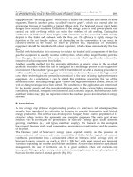
Fig. 6. The initialization for the mutual registration between level 2 and 1 using the assignment
results at level 3
(a) (b) (c) (d)
(e) (f) (g) (h)
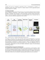
Fig. 7. The result of mutual registration between level 2 and 1, (a)(e): centers of two patches
in S
A,2
; (b)(f): centers of their correspondent patches in S
B,1
; (c)(g): centers of two patches in
S
B,2
where most probable correspondence assignment in S
B,1
of (a)(e) are their subpatches;
(d)(h): centers of the correspondent patches of (c)(g) in S
A,2
; the size of the dots in (b)(d)(f)(h)
represents the probability of the correspondence assignment
The correspondence assignment using the graphical model based mutual registration is then
carried out on them. The underlying graph topology G is selected as a random graph, in
which the degree of each node is at least 5 (connected with 5 nearest neighbours) and the
average degree of one node is 10. Λ
′
= Diag(σ
2
D
,σ
2
A
,σ
2
AL
)
−1
in (4) is selected as σ
D
= d
i,j
A,l
/4,
σ
A
= σ
AL
= 20
∘
.
∙ The results of the mutual registration at the coarsest level l
= 3 and l = 2 are shown in
Fig. 5. Obviously the two surfaces are already roughly aligned at the coarsest level and
this shows that the proposed algorithm does not ask for any initialization.
∙ The registration result at coarser level is then used to initialize the correspondence as-
signment at finer level as shown in Fig. 6. It can be observed that the number of candi-
dates of each landmark at a finer level is greatly reduced due to the initialization.
∙ The advantage of the parallel mutual registration between the two surfaces can be ob-
served from Fig. 7. The mutual registration can explore the shape information of two
surfaces and exchange correspondence assignment information between them. This
strong constraint forces the correspondent landmarks on two surfaces to mutually as-
sign to each other quickly. It’s observed during the experiment the belief propagation
at each level can converge in less than 10 iterations.
∙ As mentioned before, the goal of a nonrigid registration is to find optimal correspon-
dence assignment between shapes. Since both surfaces are generated from the same
PCA model, each landmark on a surface carries a point index in the PCA model. We
take the landmarks with the same point index on the two surfaces as the ground truth
of the correspondence assignment and then compute the registration error as the dis-
tance between the correspondent landmark obtained by our registration algorithm and
the ground truth position from prior knowledge of the PCA model. The registration
error is evaluated on both shapes as 2.7
± 2.3mm. Of course the prior correspondence
knowledge may not be the ground truth but it can be regarded as a proper reference.
5. Conclusions
In this paper we proposed a fully automatic scheme for nonrigid surface matching. The non-
rigid surface matching is formalized as a graphical model based Bayesian inference and the
belief propagation is used to achieve the optimization to find the optimal correspondence as-
signment between shapes. To further reduce the computational cost and enhance the robust-
ness to noise and local optima, a hierarchical mutual registration strategy is implemented so
that the shape information of the two surfaces can be simultaneously explored. Experiments
on randomly generated surfaces from a PCA based statistical model showed the capability of
the proposed algorithm to achieve an automatic nonrigid surface registration.
The proposed scheme can also be extended to incorporate other shape descriptors such as the
Gaussian curvature as used in (Xiao et al., 2007) and the shape context (Belongie et al., 2002)
since they can be easily modeled as local believes of each vertex in our graphical model based
scheme.
One limitation of the proposed algorithm lies in the way that it handles the nonrigid defor-
mation. Different from the commonly used TPS based deformation energy to set constraints on
the shape deformation, our algorithm encodes a nonrigid deformation by the deformation of
the subparts of a shape such as the distances and angles between landmarks. It’s difficult to
design a metric, which can accurately evaluate the deformation energy. Future work will be
carried out to design better cost functions, which can measure the deformation energy more
accurately by combining more shape information including local information such as curva-
ture and deformation energies at different representation levels.
6. References
Cootes, T., Taylor, C.: Statistical models of appearance for computer vision. Technical report,
University of Manchester, U.K. (2004)
Xu, C., Yezzi, A., Prince, J.: A summary of geometric level-set analogues for a general class of
parametric active contour and surface models (2001)
Lee, S.M., Abbott, A.L., Clark, N.A., Araman, P.A.: A shape representation for planar curves
by shape signature harmonic embedding. In: CVPR06. (2006) 1940 – 1947
Roy, A.S., Gopinath, A., Rangarajan, A.: Deformable density matching for 3d non-rigid regis-
tration of shapes. In: MICCAI 2007. (2007) 942–949
Jiang, Y.F., Xie, J., Sun, D.Q., Tsui, H.: Shape registration by simultaneously optimizing repre-
sentation and transformation. In: MICCAI 2007. (2007) 809–817
BiomedicalEngineering594
Belongie, S., Malik, J., Puzicha, J.: Shape matching and object recognition using shape con-
texts. IEEE Transactions on Pattern Analyis and Machine Intelligence 24 (2002) 509–
522
Jain, V., Zhang, H.: Robust 3d shape correspondence in the spectral domain. In: International
Conference on Shape Modeling and Applications(SMI). (2006)
Coughlan, J., Ferreira, S.: Finding deformable shapes using loopy belief propagation. In:
ECCV’02. (2002) 453–468
Caetano, T.S., Caeli, T., Barone, D.A.C.: An optimal probabilistic graphical model for point
set matching. Technical Report Technical Report TR 04-03, University of Alberta,
Edmonton, Alberta Canada (2004)
Rangarajan, A., Coughlan, J., Yuille, A.L.: A bayesian network framework for relational shape
matching. In: ICCV’03. (2003) 671–678
Zhang, L., Seitz, S.M.: Parameter estimation for mrf stereo. In: CVPR’05. (2005) 288–295
Sun, J., Zheng, N.N., Shum, H.Y.: Stereo matching using belief propagation. IEEE Transactions
on Pattern Analysis and Machine Interlligence 25 (2003) 1–14
Xiao, P.D., Barnes, N., Caetano, T., Lieby, P.: An MRF and Gaussian curvature based shape
representation for shape matching. In: CVPR07. (2007) 17–22
Gibbs, A.L.: Bounding the convergence time of the gibbs sampler in bayesian image restroat-
ion. Biometrika 87(4) (2000) 749–766
McEliece, R.J., MacKay, D.J.C., Cheng, J.F.: Turbo decoding as an instance of pearl’s ”be-
liefpropagation” algorithm. IEEE Journal on Selected Areas in Communications 16
(1998) 140–152
IntelligentandPersonalisedHydrocephalusTreatmentandManagement 595
IntelligentandPersonalisedHydrocephalusTreatmentandManagement
LinaMomani,AbdelRahmanAlkharabshehandWaleedAl-Nuaimy
X
Intelligent and Personalised Hydrocephalus
Treatment and Management
Lina Momani, Abdel Rahman Alkharabsheh and Waleed Al-Nuaimy
University of Liverpool
United Kingdom
1. Introduction
Personalised healthcare is primarily concerned with the devolution of patient monitoring
and treatment from the hospital to the home. Solutions, such as body-worn sensors for
clinical and healthcare monitoring, improve the quality of life by offering patients greater
independence. Such solutions can go beyond monitoring to active intervention and
treatment based on sensory measurement and patient feedback, effectively taking healthcare
out of the hospital environment. Such personalised healthcare solutions play an increasingly
important role in delivering high quality and cost-effective healthcare.
The realisation of truly autonomous systems for the personalised treatment of physiological
disorders such as hydrocephalus is closer than ever. This chapter is concerned with the
spreading of awareness, particularly among the biomedical engineering community e.g.
organisations, companies, physicians and patients, about the possibilities that current
technology offers in the area of intelligent and personalised hydrocephalus implants that
seek to autonomously manage the symptoms and treat the causes in a manner specifically
tuned to the individual patient. This chapter provides an insight into the workings of such a
system, its pros and cons and how it can dramatically reduce patient suffering and long
hospitalisation periods while increasing the quality of care that is provided.
1.1 Hydrocephalus
The human brain is surrounded by a fluid called the cerebrospinal fluid (CSF), that protects
it from physical injury, keeps its tissue moist and transports the products of metabolism.
This fluid is constantly produced in the parenchyma at rate of approximately 20ml.h
−1
and
drained through granulations near the sagittal sinus. If the rate of CSF absorption or
drainage is consistently less than the rate of production (for a variety of reasons), the
ventricles expand causing the brain to become compressed, leading to the disorder known
as hydrocephalus (ASBAH, 2009), as shown in Fig. 1.
33
BiomedicalEngineering596
(a) (b)
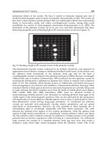
Fig. 1. Schematic drawing for brain in (a) normal and (b) hydrocephalus cases, showing
enlarged ventricles.
This leads to an elevation of the pressure exerted by the cranium on the brain tissue,
cerebrospinal fluid, and the brain’s circulating blood volume, referred to as intracranial
pressure (ICP), and manifest itself in symptoms such as headache, vomiting, nausea or
coma. ICP is a dynamic phenomenon constantly fluctuating in response to activities such as
exercise, coughing, straining, arterial pulsation, and respiratory cycle. ICP is measured in
millimeters of mercury (mmHg) and, at rest, is normally 7-15 mmHg for a supine adult, and
becomes negative (averaging -10 mmHg) in the vertical position (Steiner & Andrews, 2006).
Hydrocephalic patients may experience pressures of up to 120 mmHg. If left untreated,
elevated ICP may lead to serious problems in the brain.
1.2 Current Treatment
Since the 1960s the usual treatment for hydrocephalus is to insert a shunting device in the
patient’s CSF system. This is simply a device which diverts the accumulated CSF around the
obstructed pathways and returns it to the bloodstream, thus reducing ICP, and alleviating
the symptoms of hydrocephalus. It consists of a flexible tube with a valve to control the rate
of drainage and prevent back-flow.
These valves are passive mechanical devices that open and close depending on either the
differential pressure or flow. Although there are various valve technologies and approaches,
they all essentially do the same thing, which is to attempt to passively control the symptoms
of hydrocephalus by assisting the body’s natural drainage system. The valve is usually
chosen by the surgeon on the grounds of experience, cost and personal preference.
Despite shunting developments, shunting can have complications, with different types of
shunts seemingly associated with different types of complications. Shunt complications can
be very serious and become life threatening if not discovered and treated early. However,
due to their passive mode of operation, shunt malfunctions are generally not detected before
they manifest clinically. These can be divided into issues of under-drainage, over-drainage
and infection. Over-drainage and under-drainage are typical drawbacks of such shunts,
where CSF is either drained in excess or less than needed, which could cause dramatic
effects on the patient such as brain damage. The common cause for these two drawbacks
might be an inappropriate opening/closing of the valve in respect of the duration or the
timing. In other words, valve open for too short/too long periods or it opens/closes at the
right timing.
Under-drainage is usually due to blockage of the upper or lower tubes of the shunt by in-
growing tissue, though it can also be caused by the shunt breaking or its parts becoming
disconnected from each other. The rate of blockage can be as high as 20% in the first year
after insertion, decreasing to approximately 5% per year (Casey, et al., 1997), therefore, the
clinical presentation of shunt blockage is usually dominated by signs of raised pressure as
the brain fluid (CSF) builds up. As ICP is not readily measurable, interferences must be
drawn from the symptoms presented. Sometimes the symptoms come on quickly over hour
or days, but occasionally they may develop over many weeks with intermittent headache,
and tiredness, change in behaviour or deterioration in schoolwork. Diagnosing shunt
blockage is not always straightforward. In fact, parents can be as successful at diagnosing
shunt blockage as GPs and paediatricians. Whilst additional investigations such as CT scans,
X-rays and a shunt taps may help, a definitive diagnosis is sometimes only possible through
surgery (ASBAH, 2009).
In the case of over-drainage, the shunt allows CSF to drain from the ventricles more quickly
than it is produced. If this happens suddenly, then the ventricles in the brain collapse,
tearing delicate blood vessels on the outside of the brain and causing a haemorrhage. This
can be trivial or it can cause symptoms similar to those of a stroke. If the over-drainage is
more gradual, the ventricles collapse gradually to become slit-like. This often interferes with
shunt function causing the opposite problem, high CSF pressure, to reappear. The
symptoms of over-drainage can be very similar to those of under-drainage though there are
important differences.
Difficulty in diagnosing over-/under-drainage can make treatment of this complication
particularly frustrating for patients and their families. It may be necessary to monitor ICP,
often over 24 hours. This can be done using an external pressure monitor in the scalp
connected to a recorder. Early ICP monitoring is recommended when the clinician is unable
to assess the neurological examination accurately. The main concerns are the risks of
infection, bleeding, device accuracy and drift of measurement over time. Thus to avoid these
risks, a research work is undergoing to develop implanted pressure sensors for short and
long term monitoring interrogated by telemetry (Hodgins et al., 2008).
Studies have shown that the use of an ‘antisyphon device', a small button inserted into the
shunt tubing, will often solve the over-drainage problem, but this does not always work. A
‘programmable' or adjustable shunt is intended to allow adjustment of the working pressure
of the valve without operation. The valve contains magnets, which allow the setting to be
changed by laying a second magnetic device on the scalp. This is undoubtedly useful where
the need for a valve of a different pressure arises, but the adjustable valve is no less prone to
over-drainage than any other and it cannot be used to treat this condition (Casey et al.,
1997).
IntelligentandPersonalisedHydrocephalusTreatmentandManagement 597
(a) (b)
Fig. 1. Schematic drawing for brain in (a) normal and (b) hydrocephalus cases, showing
enlarged ventricles.
This leads to an elevation of the pressure exerted by the cranium on the brain tissue,
cerebrospinal fluid, and the brain’s circulating blood volume, referred to as intracranial
pressure (ICP), and manifest itself in symptoms such as headache, vomiting, nausea or
coma. ICP is a dynamic phenomenon constantly fluctuating in response to activities such as
exercise, coughing, straining, arterial pulsation, and respiratory cycle. ICP is measured in
millimeters of mercury (mmHg) and, at rest, is normally 7-15 mmHg for a supine adult, and
becomes negative (averaging -10 mmHg) in the vertical position (Steiner & Andrews, 2006).
Hydrocephalic patients may experience pressures of up to 120 mmHg. If left untreated,
elevated ICP may lead to serious problems in the brain.
1.2 Current Treatment
Since the 1960s the usual treatment for hydrocephalus is to insert a shunting device in the
patient’s CSF system. This is simply a device which diverts the accumulated CSF around the
obstructed pathways and returns it to the bloodstream, thus reducing ICP, and alleviating
the symptoms of hydrocephalus. It consists of a flexible tube with a valve to control the rate
of drainage and prevent back-flow.
These valves are passive mechanical devices that open and close depending on either the
differential pressure or flow. Although there are various valve technologies and approaches,
they all essentially do the same thing, which is to attempt to passively control the symptoms
of hydrocephalus by assisting the body’s natural drainage system. The valve is usually
chosen by the surgeon on the grounds of experience, cost and personal preference.
Despite shunting developments, shunting can have complications, with different types of
shunts seemingly associated with different types of complications. Shunt complications can
be very serious and become life threatening if not discovered and treated early. However,
due to their passive mode of operation, shunt malfunctions are generally not detected before
they manifest clinically. These can be divided into issues of under-drainage, over-drainage
and infection. Over-drainage and under-drainage are typical drawbacks of such shunts,
where CSF is either drained in excess or less than needed, which could cause dramatic
effects on the patient such as brain damage. The common cause for these two drawbacks
might be an inappropriate opening/closing of the valve in respect of the duration or the
timing. In other words, valve open for too short/too long periods or it opens/closes at the
right timing.
Under-drainage is usually due to blockage of the upper or lower tubes of the shunt by in-
growing tissue, though it can also be caused by the shunt breaking or its parts becoming
disconnected from each other. The rate of blockage can be as high as 20% in the first year
after insertion, decreasing to approximately 5% per year (Casey, et al., 1997), therefore, the
clinical presentation of shunt blockage is usually dominated by signs of raised pressure as
the brain fluid (CSF) builds up. As ICP is not readily measurable, interferences must be
drawn from the symptoms presented. Sometimes the symptoms come on quickly over hour
or days, but occasionally they may develop over many weeks with intermittent headache,
and tiredness, change in behaviour or deterioration in schoolwork. Diagnosing shunt
blockage is not always straightforward. In fact, parents can be as successful at diagnosing
shunt blockage as GPs and paediatricians. Whilst additional investigations such as CT scans,
X-rays and a shunt taps may help, a definitive diagnosis is sometimes only possible through
surgery (ASBAH, 2009).
In the case of over-drainage, the shunt allows CSF to drain from the ventricles more quickly
than it is produced. If this happens suddenly, then the ventricles in the brain collapse,
tearing delicate blood vessels on the outside of the brain and causing a haemorrhage. This
can be trivial or it can cause symptoms similar to those of a stroke. If the over-drainage is
more gradual, the ventricles collapse gradually to become slit-like. This often interferes with
shunt function causing the opposite problem, high CSF pressure, to reappear. The
symptoms of over-drainage can be very similar to those of under-drainage though there are
important differences.
Difficulty in diagnosing over-/under-drainage can make treatment of this complication
particularly frustrating for patients and their families. It may be necessary to monitor ICP,
often over 24 hours. This can be done using an external pressure monitor in the scalp
connected to a recorder. Early ICP monitoring is recommended when the clinician is unable
to assess the neurological examination accurately. The main concerns are the risks of
infection, bleeding, device accuracy and drift of measurement over time. Thus to avoid these
risks, a research work is undergoing to develop implanted pressure sensors for short and
long term monitoring interrogated by telemetry (Hodgins et al., 2008).
Studies have shown that the use of an ‘antisyphon device', a small button inserted into the
shunt tubing, will often solve the over-drainage problem, but this does not always work. A
‘programmable' or adjustable shunt is intended to allow adjustment of the working pressure
of the valve without operation. The valve contains magnets, which allow the setting to be
changed by laying a second magnetic device on the scalp. This is undoubtedly useful where
the need for a valve of a different pressure arises, but the adjustable valve is no less prone to
over-drainage than any other and it cannot be used to treat this condition (Casey et al.,
1997).
BiomedicalEngineering598
One of the obvious reasons for such drawbacks is the inability of such shunts to
autonomously respond to the dynamic environment. Inaccuracies and long term drift are
also considered among the drawbacks of such shunts. This is mainly due to the fact that
these shunts are (typically, but not always) regulated according to the differential pressure
across the valves, which differs from intracranial pressure in the brain.
1.3 Motivations
Beside their documented drawbacks (Aschoff, 2001; Schley, 2004), shunts do not suit many
hydrocephalus patients. This can be realised from the considerable high shunt revision and
failure rates (between 30% and 40% of all shunts placed in paediatric patients fail within 1
year (Albright et al., 1988; Villavicencio et al., 2003; Piatt et al.,1993; Piatt,1995) and it is not
uncommon for patients to have multiple shunt revisions within their lifetime).
Shunt insertion explicitly changes the CSF dynamics in patients with hydrocephalus,
causing many to improve clinically. However, the relationship between a changed
hydrodynamic state and improved clinical performance is not fully known. Therefore,
further research in this area is an important challenge for the hydrocephalus research
community, where development of better methods for assessment of CSF dynamic
parameters as well as studies to test hypotheses on relationships between CSF dynamics and
outcome after shunting is targeted. The aims are for a better understanding of
hydrocephalus pathophysiology and to find new predictive tests.
Furthermore, the shunt designers had changed the shunt goal to have the option of re-
establishing shunt independence step by step. This means that the statement of Hemmer
“once a shunt, always a shunt” is no longer true.
Nevertheless, most patients seem to be only partially shunt-dependent, i.e. their natural
drainage system still functions to some extent. The degree of shunt-dependence may range
from 1% to 100%, thus draining 30-50% of CSF production may be sufficient to keep the ICP
within physiological ranges, and only a few need full drainage (Aschoff, 2001). Thus the
current generation of shunts do not help patients overcome the underlying problems, but on
the contrary, they tend to encourage the patients to become fully shunt dependent. Research
has shown however, that in some cases, shunt dependence could be reduced to less than 1%
(Aschoff, 2001) which could even allow the eventual removal of the shunt (Takahashi, 2001).
It is envisaged that the next generation of shunts should be able to achieve a controlled
shunt arrest in the long run.
The future will bring other options related to the control of CSF production and absorption.
Perhaps different valve designs will be more effective in long-term treatment and eventually
the development of “smart” shunts. These will be able to react to intracranial physiology
and will drain CSF in response to these changes in intracranial dynamics, rather than drain
on a continuous basis (Jones & Klinge, 2008).
To address the lack of personalised treatment, the difficulty in diagnosing shunt faults, the
high rate of shunt revisions, the high shunt dependency, and the lack of full understanding
of shunt effect on the intracranial hydrodynamics, a personalised hydrocephalus shunting
system needs to be developed. This would be tasked with the following:
Frequent non-invasive monitoring of intracranial hydrodynamics to improve
treatment outcome.
Responding to patient symptoms and ICP readings by adjusting treatment.
Controlling the flow of CSF through a valve of the shunting system.
Attempting to wean patient off the treatment (shunting system).
Wirelessly reprogramming the implanted shunting system.
Instant diagnosis of the shunting system and detection of any fault in the early
stages.
By having such system, the hospitalisation periods and patient suffering and inconvenience
are reduced, the quality of treatment is improved and better understanding of intracranial
hydrodynamics is established thanks to the valuable resource of ICP data.
1.4 Recent Advances
In order to achieve such a system, a mechatronic valve is needed which is electrically
controlled via software. In this shunting system, the patient could play a vital role in feeding
back his/her dissatisfaction, i.e. due to symptoms, regarding the treatment.
In 2005, Miethke claimed patent to a hydrocephalus valve with an electric actuating system
comprising a time control system to open and close it (Miethke, 2005). The claim was that
such valve would allow improved adaptation to the situation existing in a patient in the case
of a hydrocephalus valve.
The intervention of a mechatronic valve provides the opportunity for different shunting
systems to be developed. This type of valve can be controlled by software that can vary in its
complexity and intelligence. The controlling methods could vary from a simple program
that lacks any intelligence to very sophisticated and intelligent program.
Despite ICP monitoring currently being an invasive procedure, patients with hydrocephalus
may need repeated episodes of monitoring months or years apart. This is a result of
problems arising in which ICP readings are needed for diagnosis. The invasive nature of
ICP monitoring has motivated researchers to develop a telemetric implantable pressure
sensor for short- and long-term monitoring of ICP with high accuracy (Hodgins et al., 2008).
Such sensor was mainly used for monitoring ICP wirelessly by the physician who could
manually adjust the valve settings accordingly.
The remainder of the chapter is structured as follows: Section 2 describes the intelligent and
personalised shunting system, illustrates its novelty, and lists its functions. In Section 3, the
advantages and limitations of the shunting system are identified. Section 4 summaries a
quick walkthrough of the shunting system, while Sections 5 and 6 present the future
directions and conclusions, respectively.
IntelligentandPersonalisedHydrocephalusTreatmentandManagement 599
One of the obvious reasons for such drawbacks is the inability of such shunts to
autonomously respond to the dynamic environment. Inaccuracies and long term drift are
also considered among the drawbacks of such shunts. This is mainly due to the fact that
these shunts are (typically, but not always) regulated according to the differential pressure
across the valves, which differs from intracranial pressure in the brain.
1.3 Motivations
Beside their documented drawbacks (Aschoff, 2001; Schley, 2004), shunts do not suit many
hydrocephalus patients. This can be realised from the considerable high shunt revision and
failure rates (between 30% and 40% of all shunts placed in paediatric patients fail within 1
year (Albright et al., 1988; Villavicencio et al., 2003; Piatt et al.,1993; Piatt,1995) and it is not
uncommon for patients to have multiple shunt revisions within their lifetime).
Shunt insertion explicitly changes the CSF dynamics in patients with hydrocephalus,
causing many to improve clinically. However, the relationship between a changed
hydrodynamic state and improved clinical performance is not fully known. Therefore,
further research in this area is an important challenge for the hydrocephalus research
community, where development of better methods for assessment of CSF dynamic
parameters as well as studies to test hypotheses on relationships between CSF dynamics and
outcome after shunting is targeted. The aims are for a better understanding of
hydrocephalus pathophysiology and to find new predictive tests.
Furthermore, the shunt designers had changed the shunt goal to have the option of re-
establishing shunt independence step by step. This means that the statement of Hemmer
“once a shunt, always a shunt” is no longer true.
Nevertheless, most patients seem to be only partially shunt-dependent, i.e. their natural
drainage system still functions to some extent. The degree of shunt-dependence may range
from 1% to 100%, thus draining 30-50% of CSF production may be sufficient to keep the ICP
within physiological ranges, and only a few need full drainage (Aschoff, 2001). Thus the
current generation of shunts do not help patients overcome the underlying problems, but on
the contrary, they tend to encourage the patients to become fully shunt dependent. Research
has shown however, that in some cases, shunt dependence could be reduced to less than 1%
(Aschoff, 2001) which could even allow the eventual removal of the shunt (Takahashi, 2001).
It is envisaged that the next generation of shunts should be able to achieve a controlled
shunt arrest in the long run.
The future will bring other options related to the control of CSF production and absorption.
Perhaps different valve designs will be more effective in long-term treatment and eventually
the development of “smart” shunts. These will be able to react to intracranial physiology
and will drain CSF in response to these changes in intracranial dynamics, rather than drain
on a continuous basis (Jones & Klinge, 2008).
To address the lack of personalised treatment, the difficulty in diagnosing shunt faults, the
high rate of shunt revisions, the high shunt dependency, and the lack of full understanding
of shunt effect on the intracranial hydrodynamics, a personalised hydrocephalus shunting
system needs to be developed. This would be tasked with the following:
Frequent non-invasive monitoring of intracranial hydrodynamics to improve
treatment outcome.
Responding to patient symptoms and ICP readings by adjusting treatment.
Controlling the flow of CSF through a valve of the shunting system.
Attempting to wean patient off the treatment (shunting system).
Wirelessly reprogramming the implanted shunting system.
Instant diagnosis of the shunting system and detection of any fault in the early
stages.
By having such system, the hospitalisation periods and patient suffering and inconvenience
are reduced, the quality of treatment is improved and better understanding of intracranial
hydrodynamics is established thanks to the valuable resource of ICP data.
1.4 Recent Advances
In order to achieve such a system, a mechatronic valve is needed which is electrically
controlled via software. In this shunting system, the patient could play a vital role in feeding
back his/her dissatisfaction, i.e. due to symptoms, regarding the treatment.
In 2005, Miethke claimed patent to a hydrocephalus valve with an electric actuating system
comprising a time control system to open and close it (Miethke, 2005). The claim was that
such valve would allow improved adaptation to the situation existing in a patient in the case
of a hydrocephalus valve.
The intervention of a mechatronic valve provides the opportunity for different shunting
systems to be developed. This type of valve can be controlled by software that can vary in its
complexity and intelligence. The controlling methods could vary from a simple program
that lacks any intelligence to very sophisticated and intelligent program.
Despite ICP monitoring currently being an invasive procedure, patients with hydrocephalus
may need repeated episodes of monitoring months or years apart. This is a result of
problems arising in which ICP readings are needed for diagnosis. The invasive nature of
ICP monitoring has motivated researchers to develop a telemetric implantable pressure
sensor for short- and long-term monitoring of ICP with high accuracy (Hodgins et al., 2008).
Such sensor was mainly used for monitoring ICP wirelessly by the physician who could
manually adjust the valve settings accordingly.
The remainder of the chapter is structured as follows: Section 2 describes the intelligent and
personalised shunting system, illustrates its novelty, and lists its functions. In Section 3, the
advantages and limitations of the shunting system are identified. Section 4 summaries a
quick walkthrough of the shunting system, while Sections 5 and 6 present the future
directions and conclusions, respectively.
BiomedicalEngineering600
2. Intelligent and Personalised Shunting System
The new generation of shunting systems are expected to overcome the drawbacks and
limitations of the current shunting systems. A novel intelligent telemetric system is
developed for the improved management and treatment of hydrocephalus. The intelligent
system would autonomously manage the CSF flow, personalise the management of CSF
flow through involving real-time intracranial pressure readings and patient’s feedback, and
responding to them. It also would autonomously manage and personalise the treatment of
hydrocephalus, thus providing treatment that is personalised, goal-driven and reactive as
well as pro-active, which gradually reduce shunt dependence and eventually establish a
controlled arrest of the shunt. In addition, it would be able to monitor performance of its
components, thus minimising the shunt revisions, and establish distant treatment database
(e.g. computer-based patient record) and exchange treatment information, by regularly
reporting the patient’s record to the physician.
All these qualities can only be attained by a multi-agent approach (Momani, et al., 2008).
This would also involve replacing a passive valve (commonly used in hydrocephalus
shunts) with a mechatronic valve controlled by an intelligent microcontroller that wirelessly
communicates with a separate smart hand-held device. The system is illustrated in Fig. 2.
This shunting system would consist of two subsystems; implantable and external (patient
device). The implanted subsystem would mainly consist of ultra low power commercial
microcontroller, mechatronic valve, pressure sensor and low power transceiver. This
implantable shunting system would wirelessly communicate with a hand-held smartphone
operated by the patient, or on the patient’s behalf by a clinician or guardian. This device
would have a graphical user interface and an RF interface to communicate with the user and
the implantable wireless shunt respectively.
This system would also enable a physician to monitor and modify the treatment parameters
wirelessly, thus reducing, if not eliminating, the need for shunt revision operations. Once
implanted, such a system could lead not only to better treatment of the users of such shunts,
but also allow the dynamics of this disease and the effect of shunting to be understood in
greater depth.
An intelligent system, e.g. (Momani et al., 2008) , can be used to autonomously regulate the
mechatronic valve according to a time-based schedule and update it based on the
intracranial pressure that is measured when needed. In such system, ICP readings and other
sensory inputs such as patient feedback would help in tuning the treatment and enabling
the intervention of the medical practitioner to update and manually adapt the schedule. This
would result in a personalised and intelligent CSF management, which leads to every
patient having different management schedule according to his/her personal conditions.
2.1 Novelty
The idea of using a pressure sensor integrated into a shunt system for monitoring ICP and
interrogated by telemetry is not in itself a novel idea (Ginggen, 2007; Jeong et al., 2004;
Miesel & Stylos, 2001), where ICP readings used by the physician to monitor the
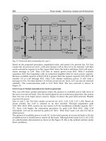
Fig. 2. Schematic diagram of the intelligent and personalised shunting system.
performance of the implanted shunt. However, the novelty in this work is in having an
implantable shunting system that utilise these readings in addition to patient input as a
direct feedback to instantaneously and even autonomously manage the shunt, i.e. analyse
the feedback, diagnose any shunt faults and accordingly regulate the opening of a
mechatronic valve. Thus an element of intelligence and personalisation would be added to
the mechatronic shunting system by enabling real-time reconfiguration of the shunt
parameters based on the patient’s response and the ICP readings.
2.2 Strategy and Approach
The mechatronic valve is controlled by a time based schedule. The schedule would be
simply the distribution of the valve state (open/close) over time. Such schedule would incur
many disadvantages e.g. over-/under-drainage, if its selection is arbitrary. In order to
optimise the usefulness of such a valve, its schedule should be selected in way that delivers
a personalised treatment for each specific patient. Achieving such a goal is not an easy task
IntelligentandPersonalisedHydrocephalusTreatmentandManagement 601
2. Intelligent and Personalised Shunting System
The new generation of shunting systems are expected to overcome the drawbacks and
limitations of the current shunting systems. A novel intelligent telemetric system is
developed for the improved management and treatment of hydrocephalus. The intelligent
system would autonomously manage the CSF flow, personalise the management of CSF
flow through involving real-time intracranial pressure readings and patient’s feedback, and
responding to them. It also would autonomously manage and personalise the treatment of
hydrocephalus, thus providing treatment that is personalised, goal-driven and reactive as
well as pro-active, which gradually reduce shunt dependence and eventually establish a
controlled arrest of the shunt. In addition, it would be able to monitor performance of its
components, thus minimising the shunt revisions, and establish distant treatment database
(e.g. computer-based patient record) and exchange treatment information, by regularly
reporting the patient’s record to the physician.
All these qualities can only be attained by a multi-agent approach (Momani, et al., 2008).
This would also involve replacing a passive valve (commonly used in hydrocephalus
shunts) with a mechatronic valve controlled by an intelligent microcontroller that wirelessly
communicates with a separate smart hand-held device. The system is illustrated in Fig. 2.
This shunting system would consist of two subsystems; implantable and external (patient
device). The implanted subsystem would mainly consist of ultra low power commercial
microcontroller, mechatronic valve, pressure sensor and low power transceiver. This
implantable shunting system would wirelessly communicate with a hand-held smartphone
operated by the patient, or on the patient’s behalf by a clinician or guardian. This device
would have a graphical user interface and an RF interface to communicate with the user and
the implantable wireless shunt respectively.
This system would also enable a physician to monitor and modify the treatment parameters
wirelessly, thus reducing, if not eliminating, the need for shunt revision operations. Once
implanted, such a system could lead not only to better treatment of the users of such shunts,
but also allow the dynamics of this disease and the effect of shunting to be understood in
greater depth.
An intelligent system, e.g. (Momani et al., 2008) , can be used to autonomously regulate the
mechatronic valve according to a time-based schedule and update it based on the
intracranial pressure that is measured when needed. In such system, ICP readings and other
sensory inputs such as patient feedback would help in tuning the treatment and enabling
the intervention of the medical practitioner to update and manually adapt the schedule. This
would result in a personalised and intelligent CSF management, which leads to every
patient having different management schedule according to his/her personal conditions.
2.1 Novelty
The idea of using a pressure sensor integrated into a shunt system for monitoring ICP and
interrogated by telemetry is not in itself a novel idea (Ginggen, 2007; Jeong et al., 2004;
Miesel & Stylos, 2001), where ICP readings used by the physician to monitor the
Fig. 2. Schematic diagram of the intelligent and personalised shunting system.
performance of the implanted shunt. However, the novelty in this work is in having an
implantable shunting system that utilise these readings in addition to patient input as a
direct feedback to instantaneously and even autonomously manage the shunt, i.e. analyse
the feedback, diagnose any shunt faults and accordingly regulate the opening of a
mechatronic valve. Thus an element of intelligence and personalisation would be added to
the mechatronic shunting system by enabling real-time reconfiguration of the shunt
parameters based on the patient’s response and the ICP readings.
2.2 Strategy and Approach
The mechatronic valve is controlled by a time based schedule. The schedule would be
simply the distribution of the valve state (open/close) over time. Such schedule would incur
many disadvantages e.g. over-/under-drainage, if its selection is arbitrary. In order to
optimise the usefulness of such a valve, its schedule should be selected in way that delivers
a personalised treatment for each specific patient. Achieving such a goal is not an easy task
BiomedicalEngineering602
due to the dynamic behaviour of intracranial pressure that not only varies among patients
but also within individual patient with time. There are two extremes for schedule
alternatives. One is a dynamic schedule that responds to the instantaneous intracranial
pressure which requires an implanted pressure sensor, i.e. closed loop shunting system. The
other extreme is a fixed schedule that has a fixed open frequency over 24 hours. This
alternative lacks flexibility and ignores the intracranial dynamic behaviour while the first is
impractical.
A schedule structure is proposed that offers a compromise between the two schedule
extremes. Thus to facilitate the process of schedule selection and to add some degree of
flexibility, a 24-hours schedule, shown in Fig. 3, is divided into 24 one hour sub-schedules.
Each sub-schedule is identified by three parameters; the targeted hour (hr), open duration
(d
ON
) and closed duration (d
OFF
) for that specific hour.
Treatment in the proposed shunting system is presented by a time-based valve schedule,
thus dynamically modifying the schedule, would mean changing the applied treatment.
Treatment would be modified in order to adapt to the individual patient and actual
conditions. This modification is accomplished based on real-time inputs (e.g. symptoms
delivered via patient feedback and internally measured ICP) and derived parameters such
as rate of ICP change, effective opening time and figure of merits. To update the schedule,
the modification is only applied on the targeted sub-schedule (hour).
Fig. 3. A 24-hour schedule for the implanted valve.
The system acquires knowledge directly and wirelessly from the patient's satisfaction input
(feedback), to make decision regarding modifying the schedule or it just records and saves
patient's satisfaction for future interpretation.
Once the shunting system is implanted, the system is initially programmed by taking into
consideration the empirical data patient’s history, e.g. ICP data, personal information,
medical history, family history.
In long run, the system should become stable and reach a state in which it adapts to the
patient and deals smartly and dynamically with any changes with no need for help. As a
result, these personalised schedules can be categorised according to hydrocephalus patient
types so as to develop an optimum schedule for each patient’s category that can be used, in
future, as the initial schedule when implanting such shunts.
2.3 Functions
The intelligent shunting system will perform two main roles; management and treatment.
2.3.1 Management
This involves managing both the physiological condition and the shunting system itself. The
former consists of monitoring and optimising the success of treatment, adapting the
treatment to the individual and actual conditions, responding to symptoms reported via
patient feedback and capturing real shunt dependency. On the other hand the latter covers
the self monitoring, diagnosis and fault detection. Both of those aspects are detailed below.
A. Managing Hydrocephalus
Similar to any other shunt, the proposed shunt will aim to control ICP within the normal
physiological limits. To achieve this, the following tasks are performed,
1. Monitoring the success of treatment and its optimisation: The shunt will routinely
collect ICP readings measured by the implanted sensor, analyse them internally to
check whether the current schedule succeeded in maintaining pressure within normal
range. In addition, a figure of merit is calculated to help in evaluating the performance
of treatment and in selecting a schedule that best suit the situation. The novelty of
such function would be in it is ability to collect ICP data while the valve is closed, thus
providing a valuable record of ICP for un-shunted case (without treatment) with no
need to perform any additional invasive operation. Such traces are considered
valuable in understanding specific-patient cases and the effect of applying different
schedules, since currently physician do not perform ICP monitoring before shunting
unless all other methods did not work out in diagnosing hydrocephalus due to the
risks of such procedure.
2. Adapting the treatment to the individual and actual conditions: to successfully
manage hydrocephalus, it should adapt the treatment to the needs of the specific-
patient and arising circumstances. If a problem arises in the measured ICP (e.g. ICP is
high), the system would respond dynamically and instantaneously by updating the
valve schedule according to rules saved in the knowledge base. Initially these rules
are general but with time it is revised by the shunting system to suit this particular
patient.
3. Responding to symptoms delivered via patient feedback: Nowadays, reoccurrence
of symptoms in shunted patient is usually dealt by externally monitor the ICP. Such
procedure is invasive and accompanied by many risks and complications. That is why
intracranial monitoring usually is the last option for un-shunted patient unless it is
vital to diagnose hydrocephalus in some cases. In this system, patient feedback would
be logged into the patient device to represent the type of symptom and its severity. As
a result of receiving such feedback, the shunting system will investigate the cause of
the symptom by checking the normality of ICP and perform self-checking for any
faults in the system. And later draw a conclusion whether the cause was due to
abnormality in ICP or not. In the case of any abnormality, it will respond by either
modifying the valve schedule to accommodate the symptom or alerting the physician
in case of faults possibilities.
IntelligentandPersonalisedHydrocephalusTreatmentandManagement 603
due to the dynamic behaviour of intracranial pressure that not only varies among patients
but also within individual patient with time. There are two extremes for schedule
alternatives. One is a dynamic schedule that responds to the instantaneous intracranial
pressure which requires an implanted pressure sensor, i.e. closed loop shunting system. The
other extreme is a fixed schedule that has a fixed open frequency over 24 hours. This
alternative lacks flexibility and ignores the intracranial dynamic behaviour while the first is
impractical.
A schedule structure is proposed that offers a compromise between the two schedule
extremes. Thus to facilitate the process of schedule selection and to add some degree of
flexibility, a 24-hours schedule, shown in Fig. 3, is divided into 24 one hour sub-schedules.
Each sub-schedule is identified by three parameters; the targeted hour (hr), open duration
(d
ON
) and closed duration (d
OFF
) for that specific hour.
Treatment in the proposed shunting system is presented by a time-based valve schedule,
thus dynamically modifying the schedule, would mean changing the applied treatment.
Treatment would be modified in order to adapt to the individual patient and actual
conditions. This modification is accomplished based on real-time inputs (e.g. symptoms
delivered via patient feedback and internally measured ICP) and derived parameters such
as rate of ICP change, effective opening time and figure of merits. To update the schedule,
the modification is only applied on the targeted sub-schedule (hour).
Fig. 3. A 24-hour schedule for the implanted valve.
The system acquires knowledge directly and wirelessly from the patient's satisfaction input
(feedback), to make decision regarding modifying the schedule or it just records and saves
patient's satisfaction for future interpretation.
Once the shunting system is implanted, the system is initially programmed by taking into
consideration the empirical data patient’s history, e.g. ICP data, personal information,
medical history, family history.
In long run, the system should become stable and reach a state in which it adapts to the
patient and deals smartly and dynamically with any changes with no need for help. As a
result, these personalised schedules can be categorised according to hydrocephalus patient
types so as to develop an optimum schedule for each patient’s category that can be used, in
future, as the initial schedule when implanting such shunts.
2.3 Functions
The intelligent shunting system will perform two main roles; management and treatment.
2.3.1 Management
This involves managing both the physiological condition and the shunting system itself. The
former consists of monitoring and optimising the success of treatment, adapting the
treatment to the individual and actual conditions, responding to symptoms reported via
patient feedback and capturing real shunt dependency. On the other hand the latter covers
the self monitoring, diagnosis and fault detection. Both of those aspects are detailed below.
A. Managing Hydrocephalus
Similar to any other shunt, the proposed shunt will aim to control ICP within the normal
physiological limits. To achieve this, the following tasks are performed,
1. Monitoring the success of treatment and its optimisation: The shunt will routinely
collect ICP readings measured by the implanted sensor, analyse them internally to
check whether the current schedule succeeded in maintaining pressure within normal
range. In addition, a figure of merit is calculated to help in evaluating the performance
of treatment and in selecting a schedule that best suit the situation. The novelty of
such function would be in it is ability to collect ICP data while the valve is closed, thus
providing a valuable record of ICP for un-shunted case (without treatment) with no
need to perform any additional invasive operation. Such traces are considered
valuable in understanding specific-patient cases and the effect of applying different
schedules, since currently physician do not perform ICP monitoring before shunting
unless all other methods did not work out in diagnosing hydrocephalus due to the
risks of such procedure.
2. Adapting the treatment to the individual and actual conditions: to successfully
manage hydrocephalus, it should adapt the treatment to the needs of the specific-
patient and arising circumstances. If a problem arises in the measured ICP (e.g. ICP is
high), the system would respond dynamically and instantaneously by updating the
valve schedule according to rules saved in the knowledge base. Initially these rules
are general but with time it is revised by the shunting system to suit this particular
patient.
3. Responding to symptoms delivered via patient feedback: Nowadays, reoccurrence
of symptoms in shunted patient is usually dealt by externally monitor the ICP. Such
procedure is invasive and accompanied by many risks and complications. That is why
intracranial monitoring usually is the last option for un-shunted patient unless it is
vital to diagnose hydrocephalus in some cases. In this system, patient feedback would
be logged into the patient device to represent the type of symptom and its severity. As
a result of receiving such feedback, the shunting system will investigate the cause of
the symptom by checking the normality of ICP and perform self-checking for any
faults in the system. And later draw a conclusion whether the cause was due to
abnormality in ICP or not. In the case of any abnormality, it will respond by either
modifying the valve schedule to accommodate the symptom or alerting the physician
in case of faults possibilities.
BiomedicalEngineering604
The availability of such option in the proposed shunting system, spares patient from
unnecessary pain, suffering and risks accompanied with the current diagnosis
method. And on the contrary to current methods, this option will provide an instant
diagnosing while the patient is living his/her normal life, thus no need to wait for an
appointment or being hospitalised
4. Capturing real shunt dependency: Knowing that patients seem to be only partially
shunt-dependent, the current shunts do not help in revealing the degree of
dependency, but on the contrary, they tend to encourage the patients to become fully
shunt dependent. Proposed shunting system can help in revealing the actual shunt
dependency, thus allowing the natural drainage to keep working at its maximum
power and the shunt will only give a hand when the natural drainage is overloaded.
B. Managing the Shunting System
It is important that the system functions properly so that a reasonable intracranial pressure
is maintained. Currently, shunt faults are the leading cause of shunt revisions. The main
shunt faults are blockage and disconnection. In an effort to detect these faults in early
stages, thus avoiding any further patient inconveniences that could arise if left undetected,
the proposed shunting system will perform the following preventive procedure.
1. Self monitoring: routinely check up if the ICP data changes in responsive manner to
the valve states.
2. Self diagnosis: use novel fault detection measures, which are based on ICP data and
valve status, to find any possibility of occurrence of any fault, determine its type (e.g.
shunt blockage/disconnection/breakage or sensor dislocation/drift), and its degree.
3. Power management: use a real-time self wake-up method to manage the power
consumption in the implanted shunt.
4. Memory management: use a novel method to reduce the size of stored data in the
implanted shunt, thus solving a problem associated with implanted memory
limitations.
2.3.2 Treatment
The goal of shunting has changed over time since it was first used. The shunt nowadays is
expected to provide an option of establishing gradual shunt arrest. It is also the dream of
any hydrocephalus shunted patient to regain his/her independence of the shunt and mainly
rely on his/her reconditioned natural drainage system.
The capability of the proposed system to be wirelessly reprogrammed without the need for
surgery and its ability to monitor the change in the intracranial hydrodynamics are essential
in facilitating the shunt arrest process.
At the stage when the shunting system is fully in control of the intracranial hydrodynamics
and the patient’s real shunt dependency is captured, the shunting system will start
achieving new objective that is reducing shunt dependency and might eventually arrest the
use of the shunt (weaning).
The weaning process will involve manipulating two parameters; the length of open duration
and the limits of acceptable pressure (above which ICP is considered abnormal), in away
that make the patient either adapt gradually to higher level of ICP or reactivate the natural
drainage to take part of the drainage process. Weaning will be implemented over stages.
The length of each stage will vary based on patient response and capability to accommodate
such change. For each weaning stage, the effect of modifying weaning parameters will be
evaluated by routinely collecting ICP readings and patient feedback. The amount of
reduction in the open duration or increase in the acceptable pressure limits will depend on
parameters derived from patient’s ICP data at different valve states.
3. Advantages and Limitations
The shunting system is explored and its advantages are identified. Furthermore, limitations
facing implementing such system are investigated.
3.1 Advantages
Compared to the current shunts, this shunting system offers the following advantages:
o Personalising: responsive to patient needs and situation.
o Autonomous: functions without supervision or intervention.
o Reducing patient suffering, e.g. hospitalisation.
o Managing and responding to symptoms obtained from patient feedback.
o Autonomous monitoring and diagnosis of intracranial hydrodynamics.
o Potential to achieve arrest of shunt dependence.
o Wireless reprogramming; access, modify and replace current parameters.
o Ability to obtain ICP traces for patient both with and without shunt.
o Shunt self diagnosis and fault detection.
o Better understanding of hydrocephalus, intracranial hydrodynamics and the effect of
shunting on them.
3.2 Limitations
The following limitations are encountered when implementing such system:
o ICP sensor inaccuracy or breakage
o Mechatronic valve intermittent problems
o Physician and patient mentality
o Technical issues
o Power limitation
o Implantable memory size limitation
o Product size limitation
o Potential faults
4. Walkthrough
A quick walk through the shunting system is summarised. It illustrates the shunt functions
through an example of one day in the life of shunted hydrocephalus patient.
IntelligentandPersonalisedHydrocephalusTreatmentandManagement 605
The availability of such option in the proposed shunting system, spares patient from
unnecessary pain, suffering and risks accompanied with the current diagnosis
method. And on the contrary to current methods, this option will provide an instant
diagnosing while the patient is living his/her normal life, thus no need to wait for an
appointment or being hospitalised
4. Capturing real shunt dependency: Knowing that patients seem to be only partially
shunt-dependent, the current shunts do not help in revealing the degree of
dependency, but on the contrary, they tend to encourage the patients to become fully
shunt dependent. Proposed shunting system can help in revealing the actual shunt
dependency, thus allowing the natural drainage to keep working at its maximum
power and the shunt will only give a hand when the natural drainage is overloaded.
B. Managing the Shunting System
It is important that the system functions properly so that a reasonable intracranial pressure
is maintained. Currently, shunt faults are the leading cause of shunt revisions. The main
shunt faults are blockage and disconnection. In an effort to detect these faults in early
stages, thus avoiding any further patient inconveniences that could arise if left undetected,
the proposed shunting system will perform the following preventive procedure.
1. Self monitoring: routinely check up if the ICP data changes in responsive manner to
the valve states.
2. Self diagnosis: use novel fault detection measures, which are based on ICP data and
valve status, to find any possibility of occurrence of any fault, determine its type (e.g.
shunt blockage/disconnection/breakage or sensor dislocation/drift), and its degree.
3. Power management: use a real-time self wake-up method to manage the power
consumption in the implanted shunt.
4. Memory management: use a novel method to reduce the size of stored data in the
implanted shunt, thus solving a problem associated with implanted memory
limitations.
2.3.2 Treatment
The goal of shunting has changed over time since it was first used. The shunt nowadays is
expected to provide an option of establishing gradual shunt arrest. It is also the dream of
any hydrocephalus shunted patient to regain his/her independence of the shunt and mainly
rely on his/her reconditioned natural drainage system.
The capability of the proposed system to be wirelessly reprogrammed without the need for
surgery and its ability to monitor the change in the intracranial hydrodynamics are essential
in facilitating the shunt arrest process.
At the stage when the shunting system is fully in control of the intracranial hydrodynamics
and the patient’s real shunt dependency is captured, the shunting system will start
achieving new objective that is reducing shunt dependency and might eventually arrest the
use of the shunt (weaning).
The weaning process will involve manipulating two parameters; the length of open duration
and the limits of acceptable pressure (above which ICP is considered abnormal), in away
that make the patient either adapt gradually to higher level of ICP or reactivate the natural
drainage to take part of the drainage process. Weaning will be implemented over stages.
The length of each stage will vary based on patient response and capability to accommodate
such change. For each weaning stage, the effect of modifying weaning parameters will be
evaluated by routinely collecting ICP readings and patient feedback. The amount of
reduction in the open duration or increase in the acceptable pressure limits will depend on
parameters derived from patient’s ICP data at different valve states.
3. Advantages and Limitations
The shunting system is explored and its advantages are identified. Furthermore, limitations
facing implementing such system are investigated.
3.1 Advantages
Compared to the current shunts, this shunting system offers the following advantages:
o Personalising: responsive to patient needs and situation.
o Autonomous: functions without supervision or intervention.
o Reducing patient suffering, e.g. hospitalisation.
o Managing and responding to symptoms obtained from patient feedback.
o Autonomous monitoring and diagnosis of intracranial hydrodynamics.
o Potential to achieve arrest of shunt dependence.
o Wireless reprogramming; access, modify and replace current parameters.
o Ability to obtain ICP traces for patient both with and without shunt.
o Shunt self diagnosis and fault detection.
o Better understanding of hydrocephalus, intracranial hydrodynamics and the effect of
shunting on them.
3.2 Limitations
The following limitations are encountered when implementing such system:
o ICP sensor inaccuracy or breakage
o Mechatronic valve intermittent problems
o Physician and patient mentality
o Technical issues
o Power limitation
o Implantable memory size limitation
o Product size limitation
o Potential faults
4. Walkthrough
A quick walk through the shunting system is summarised. It illustrates the shunt functions
through an example of one day in the life of shunted hydrocephalus patient.
BiomedicalEngineering606
Bob is a hydrocephalus patient. Today, he was shunted with an intelligent shunting system.
This system has been configured by the physician to suit Bob based on his medical history
(including an ICP trace) and hydrocephalus type.
Once implanted, the system will attempt to initialise itself by first collecting ICP data for 24
hours and then instantiate an initial personalised 24 sub-schedules based on hourly derived
parameters (e.g. average ICP and rate of change in ICP) from the collected data. Starting
from the first day, the implanted shunt will perform its routine tasks; ICP monitoring, valve
regulating according to the schedule, self diagnosis, and daily backup of the results.
One day Bob woke up and he was feeling drowsy. He checked if there were any alerts on his
patient device (PD) but found nothing. He started to worry that there might be a problem
with his shunt, thus he logged his feedback on his PD.
In the following few minutes, the intelligent agent on PD started to investigate the cause by
firstly sending a request for ICP data to the implanted shunt. While waiting for a reply, it
checked its database if any similar feedback that might have occurred previously at the time
of the day or if such symptom is recently reoccurring.
Meanwhile, the implanted shunting system received the request and immediately initiated
the ICP sensor to collect data over a period of time at different valve states. As soon as
sufficient data is collected, it is sent wirelessly to the PD.
By receiving the ICP, the external shunting system (PD) starts performing analysis and
calculating some derived parameters to check if the cause for such symptoms is due ICP
abnormality or shunt fault. If the results of the analysis indicated that the cause of the
symptom is not due to ICP abnormality or shunt fault, then a message will show up on the
PD display to reassure Bob that the symptom is not ICP-related. The feedback, its time along
with the ICP data and the decision made are saved to be uploaded at a later time to Bob’s
personal record in the central database at the hospital. On the other hand, if the results
showed that the cause is due to ICP abnormality, then the intelligent system will work on
modifying the schedule at that hour and track its effect for the next couple of days. A
message will also show up telling Bob that the problem has been handled. Bob in either case
was reassured that his shunting system was functioning properly and there was nothing to
worry about.
While Bob is doing his job, the implanted shunt is regulating the valve according to a time-
based schedule and at the same time perform a check up on the ICP and the shunt itself. To
do this, it collects ICP data while the valve is open and closed. It checks if these data is
within the acceptable limits and if not, it will alert the PD to perform modification on the
schedule. The implanted shunt will also calculate some derived parameter to detect any
possibility of fault occurrence in the shunt. In case any fault is detected, the implanted shunt
will inform the physician through the PD, in order to take some procedures in early stage to
spare Bob from unnecessary pain and suffering.
After one year of shunt experience, Bob confidence in his shunt has grown and he stopped
worrying about his ICP since he knows that wherever he is, he has a personal physician that
accompanies him 24 hours a day and whom will worry on his behave. Bob also pleased that
he no longer has to wait for an appointment or stay in the hospital every time he had a
symptom. He can now check up his ICP and shunt in minutes while having his normal life
anywhere and anytime.
Two years passed on the shunting surgery. Bob is happy with his shunt, he has not
experienced any symptom for long time. Thus, his shunt has recognised this progress and
decided after consulting the physician to start reducing shunt dependency (shunt weaning
process). First step was to reduce open duration for a selected hour based on Bob’s ICP
history. Bob is asked to play a vital role at this stage, by giving his feedback whenever he
has symptoms, to tune and personalise the weaning process. After checking that the first
step did not have harmful consequences, the shunt proceeded to its second step which is
attacking a new open duration and try to reduce it. Unfortunately this time Bob could not
handle the severity of the symptoms thus the shunt had to reconfigure this step to avoid any
inconvenience for Bob.
After prolong period of time, Bob’s shunt dependency has been reduced to minimum but
unfortunately Bob’s brain adaptability could not go through a complete shunt arrest.
Nevertheless, Bob was really satisfied with what his shunt has done and what he is still
doing and hopes that shunt arresting can be achieved in later time.
5. Future Directions
Future enhancements would include incorporating more parameters in developing and
modifying the valve schedule. For example, patient daily activities (sleeping and working
times, type of work (sitting, standing)) and other parameters derived from ICP traces would
enhance the performance of the valve schedule if taken into consideration when deriving or
modifying a schedule.
The significance of such intelligent personalised shunting system can be extended by
incorporating it into a distributed network of intelligent shunts, where data mining and
knowledge acquisition techniques are deployed to analyse and interpret hydrocephalus
patients’ data for case enquiring, treatment plan advising, and ICP classification and patient
clustering. In addition it would let patients exchange and share the treatment and
management process.
6. Conclusion
The realisation of truly autonomous shunting systems for personalised hydrocephalus
treatment is closer than ever. This requires the use of an implanted mechatronic valve and
pressure sensor, a smart hand held device, improved algorithms to analyse the inputs (e.g.
ICP readings and patient feedback) and extract relevant information from raw data, and
rule-based decisions controlled by local intelligence. The Management of intracranial
hydrodynamics, shunt self-diagnosis, and treatment of hydrocephalus can be continuously
IntelligentandPersonalisedHydrocephalusTreatmentandManagement 607
Bob is a hydrocephalus patient. Today, he was shunted with an intelligent shunting system.
This system has been configured by the physician to suit Bob based on his medical history
(including an ICP trace) and hydrocephalus type.
Once implanted, the system will attempt to initialise itself by first collecting ICP data for 24
hours and then instantiate an initial personalised 24 sub-schedules based on hourly derived
parameters (e.g. average ICP and rate of change in ICP) from the collected data. Starting
from the first day, the implanted shunt will perform its routine tasks; ICP monitoring, valve
regulating according to the schedule, self diagnosis, and daily backup of the results.
One day Bob woke up and he was feeling drowsy. He checked if there were any alerts on his
patient device (PD) but found nothing. He started to worry that there might be a problem
with his shunt, thus he logged his feedback on his PD.
In the following few minutes, the intelligent agent on PD started to investigate the cause by
firstly sending a request for ICP data to the implanted shunt. While waiting for a reply, it
checked its database if any similar feedback that might have occurred previously at the time
of the day or if such symptom is recently reoccurring.
Meanwhile, the implanted shunting system received the request and immediately initiated
the ICP sensor to collect data over a period of time at different valve states. As soon as
sufficient data is collected, it is sent wirelessly to the PD.
By receiving the ICP, the external shunting system (PD) starts performing analysis and
calculating some derived parameters to check if the cause for such symptoms is due ICP
abnormality or shunt fault. If the results of the analysis indicated that the cause of the
symptom is not due to ICP abnormality or shunt fault, then a message will show up on the
PD display to reassure Bob that the symptom is not ICP-related. The feedback, its time along
with the ICP data and the decision made are saved to be uploaded at a later time to Bob’s
personal record in the central database at the hospital. On the other hand, if the results
showed that the cause is due to ICP abnormality, then the intelligent system will work on
modifying the schedule at that hour and track its effect for the next couple of days. A
message will also show up telling Bob that the problem has been handled. Bob in either case
was reassured that his shunting system was functioning properly and there was nothing to
worry about.
While Bob is doing his job, the implanted shunt is regulating the valve according to a time-
based schedule and at the same time perform a check up on the ICP and the shunt itself. To
do this, it collects ICP data while the valve is open and closed. It checks if these data is
within the acceptable limits and if not, it will alert the PD to perform modification on the
schedule. The implanted shunt will also calculate some derived parameter to detect any
possibility of fault occurrence in the shunt. In case any fault is detected, the implanted shunt
will inform the physician through the PD, in order to take some procedures in early stage to
spare Bob from unnecessary pain and suffering.
After one year of shunt experience, Bob confidence in his shunt has grown and he stopped
worrying about his ICP since he knows that wherever he is, he has a personal physician that
accompanies him 24 hours a day and whom will worry on his behave. Bob also pleased that
he no longer has to wait for an appointment or stay in the hospital every time he had a
symptom. He can now check up his ICP and shunt in minutes while having his normal life
anywhere and anytime.
Two years passed on the shunting surgery. Bob is happy with his shunt, he has not
experienced any symptom for long time. Thus, his shunt has recognised this progress and
decided after consulting the physician to start reducing shunt dependency (shunt weaning
process). First step was to reduce open duration for a selected hour based on Bob’s ICP
history. Bob is asked to play a vital role at this stage, by giving his feedback whenever he
has symptoms, to tune and personalise the weaning process. After checking that the first
step did not have harmful consequences, the shunt proceeded to its second step which is
attacking a new open duration and try to reduce it. Unfortunately this time Bob could not
handle the severity of the symptoms thus the shunt had to reconfigure this step to avoid any
inconvenience for Bob.
After prolong period of time, Bob’s shunt dependency has been reduced to minimum but
unfortunately Bob’s brain adaptability could not go through a complete shunt arrest.
Nevertheless, Bob was really satisfied with what his shunt has done and what he is still
doing and hopes that shunt arresting can be achieved in later time.
5. Future Directions
Future enhancements would include incorporating more parameters in developing and
modifying the valve schedule. For example, patient daily activities (sleeping and working
times, type of work (sitting, standing)) and other parameters derived from ICP traces would
enhance the performance of the valve schedule if taken into consideration when deriving or
modifying a schedule.
The significance of such intelligent personalised shunting system can be extended by
incorporating it into a distributed network of intelligent shunts, where data mining and
knowledge acquisition techniques are deployed to analyse and interpret hydrocephalus
patients’ data for case enquiring, treatment plan advising, and ICP classification and patient
clustering. In addition it would let patients exchange and share the treatment and
management process.
6. Conclusion
The realisation of truly autonomous shunting systems for personalised hydrocephalus
treatment is closer than ever. This requires the use of an implanted mechatronic valve and
pressure sensor, a smart hand held device, improved algorithms to analyse the inputs (e.g.
ICP readings and patient feedback) and extract relevant information from raw data, and
rule-based decisions controlled by local intelligence. The Management of intracranial
hydrodynamics, shunt self-diagnosis, and treatment of hydrocephalus can be continuously
BiomedicalEngineering608
and autonomously monitored and parameters changed as necessary by the intelligent
software in the handheld device via wireless communication and data will be sent on
demand to the clinician for further evaluation. Such shunting system would give
hydrocephalus patients the freedom to go anywhere they like while receiving medical
services and health care in a timely fashion. Visits of patients to hospitals or the doctor will
be reduced to a necessary minimum, while increasing the quality of care that is provided.
7. References
Association for Spina Bifida Hydrocephalus (2009). Hydrocephalus, available online:
Albright, A.L.; Haines, S.J. & Taylor, F.H. (1988). Function of parietal and frontal shunts in
childhood hydrocephalus, J Neurosurg, vol. 69, pp. 883-886.
Aschoff, A. (2001). The evolution of shunt technology in the last decade: A critical review,
presented at 3rd International Hydrocephalus Workshop, Kos, Greece, May 17-20th,
2001.
Casey, A. T.; Kimmings, E. J.; Kleinlugtebeld, A. D.; Taylor. W. A.; Harkness, W. F. &
Hayward, R. D. (1997). The long-term outlook for hydrocephalus in childhood. (A
ten-year cohort study of 155 patients), Pediatr Neurosurg, vol. 27, no. 2, pp. 63-70.
Ginggen, A. (2007). Optimization of the Treatment of Hydrocephalus by the Non-Invasive
Measurement of the Intra-Cranial Pressure, PhD thesis, infoscienc, EPFL, Czech.
URL :
Hodgins, D.; Bertsch, A.; Post, N.; Frischholz, M.; Volckaerts, B.; Spensley, J.; Wasikiewicz, J.
M.; Higgins, H.; Stetten, F. & Kenney, L. (2008). IEEE Pervasive Computing. vol. 7,
no. 1, pp. 14-21, January–March 2008.
Jones, H. C. & Klinge, P. T. (2008). Hydrocephalus, In Hannover Conference 17–20th
September 2008, Cerebrospinal Fluid Res., 2008; vol. 5, pp. 19.
Jeong, J. S. ; Yang, S. S.; Yoon, H. J. & Jung, J. M. (2004). Micro Devices for a Cerebrospinal
Fluid (CSF) Shunt System. Sensors and Actuators A, Vol. 110, pp. 68-76.
Kramer, L. C.; Azarow, K.; Schlifka, B. A. & Sgouros, S. (2006). eMedicine Pediatrics, available
online:
Miesel, K. A. & Stylos, L. (2001). Intracranial monitoring and therapy delivery control
device, system and method, United States Patent, No. 6248080.
Miethke, C. (2005). Hydrocephalus valve, U.S. Patent 6926691, August 9, 2005.
Momani, L., Alkharabsheh, A. & Al-Nuaimy, W. (2008). Design of an intelligent and
personalised shunting system for hydrocephalus, in Conf Proc 2008 IEEE Eng Med
Biol Soc., Vancouver, Canada, pp. 779-782.
Piatt Jr, J.H. & Carlson, C.V. (1993). A search for determinants of cerebrospinal fluid shunt
survival: retrospective analysis of a 14-year institutional experience. Pediatr
Neurosurg, vol. 19, pp. 233-241.
Piatt Jr, J.H. (1995). Cerebrospinal fluid shunt failure: late is different from early. Pediatr
Neurosurg, vol. 23, pp. 133-139.
Schley, D.; Billingham, J. & Marchbanks, R. J. (2004). A Model of in-vivo hydrocephalus
shunt dynamics for blockage and performance diagnostics, Mathematical Medicine
and Biology, vol. 21, no. 4, pp. 347-368, Dec. 2004.
Steiner, L. A. & Andrews, P. J. (2006). Monitoring the injured brain: ICP and CBF, British
Journal of Anaesthesia, vol. 97, no. 1 (July 2006), pp. 26-38.
Takahashi, Y. (2001). Withdrawal of shunt systems clinical use of the programmable shunt
system and its effect on hydrocephalus in children, Childs Nerv Syst, vol. 17, pp.
472-477, Aug. 2001.
Villavicencio, A. T.; Leveque, J.; McGirt, M. J.; Hopkins, J. S.; Fuchs, H. E. & George, T. M.
(2003). Comparison of Revision Rates Following Endoscopically Versus
Nonendoscopically Placed Ventricular Shunt Catheters, Surgical Neurology, vol. 59,
no. 5, pp. 375-379.
IntelligentandPersonalisedHydrocephalusTreatmentandManagement 609
and autonomously monitored and parameters changed as necessary by the intelligent
software in the handheld device via wireless communication and data will be sent on
demand to the clinician for further evaluation. Such shunting system would give
hydrocephalus patients the freedom to go anywhere they like while receiving medical
services and health care in a timely fashion. Visits of patients to hospitals or the doctor will
be reduced to a necessary minimum, while increasing the quality of care that is provided.
7. References
Association for Spina Bifida Hydrocephalus (2009). Hydrocephalus, available online:
Albright, A.L.; Haines, S.J. & Taylor, F.H. (1988). Function of parietal and frontal shunts in
childhood hydrocephalus, J Neurosurg, vol. 69, pp. 883-886.
Aschoff, A. (2001). The evolution of shunt technology in the last decade: A critical review,
presented at 3rd International Hydrocephalus Workshop, Kos, Greece, May 17-20th,
2001.
Casey, A. T.; Kimmings, E. J.; Kleinlugtebeld, A. D.; Taylor. W. A.; Harkness, W. F. &
Hayward, R. D. (1997). The long-term outlook for hydrocephalus in childhood. (A
ten-year cohort study of 155 patients), Pediatr Neurosurg, vol. 27, no. 2, pp. 63-70.
Ginggen, A. (2007). Optimization of the Treatment of Hydrocephalus by the Non-Invasive
Measurement of the Intra-Cranial Pressure, PhD thesis, infoscienc, EPFL, Czech.
URL :
Hodgins, D.; Bertsch, A.; Post, N.; Frischholz, M.; Volckaerts, B.; Spensley, J.; Wasikiewicz, J.
M.; Higgins, H.; Stetten, F. & Kenney, L. (2008). IEEE Pervasive Computing. vol. 7,
no. 1, pp. 14-21, January–March 2008.
Jones, H. C. & Klinge, P. T. (2008). Hydrocephalus, In Hannover Conference 17–20th
September 2008, Cerebrospinal Fluid Res., 2008; vol. 5, pp. 19.
Jeong, J. S. ; Yang, S. S.; Yoon, H. J. & Jung, J. M. (2004). Micro Devices for a Cerebrospinal
Fluid (CSF) Shunt System. Sensors and Actuators A, Vol. 110, pp. 68-76.
Kramer, L. C.; Azarow, K.; Schlifka, B. A. & Sgouros, S. (2006). eMedicine Pediatrics, available
online:
Miesel, K. A. & Stylos, L. (2001). Intracranial monitoring and therapy delivery control
device, system and method, United States Patent, No. 6248080.
Miethke, C. (2005). Hydrocephalus valve, U.S. Patent 6926691, August 9, 2005.
Momani, L., Alkharabsheh, A. & Al-Nuaimy, W. (2008). Design of an intelligent and
personalised shunting system for hydrocephalus, in Conf Proc 2008 IEEE Eng Med
Biol Soc., Vancouver, Canada, pp. 779-782.
Piatt Jr, J.H. & Carlson, C.V. (1993). A search for determinants of cerebrospinal fluid shunt
survival: retrospective analysis of a 14-year institutional experience. Pediatr
Neurosurg, vol. 19, pp. 233-241.
Piatt Jr, J.H. (1995). Cerebrospinal fluid shunt failure: late is different from early. Pediatr
Neurosurg, vol. 23, pp. 133-139.
Schley, D.; Billingham, J. & Marchbanks, R. J. (2004). A Model of in-vivo hydrocephalus
shunt dynamics for blockage and performance diagnostics, Mathematical Medicine
and Biology, vol. 21, no. 4, pp. 347-368, Dec. 2004.
Steiner, L. A. & Andrews, P. J. (2006). Monitoring the injured brain: ICP and CBF, British
Journal of Anaesthesia, vol. 97, no. 1 (July 2006), pp. 26-38.
Takahashi, Y. (2001). Withdrawal of shunt systems clinical use of the programmable shunt
system and its effect on hydrocephalus in children, Childs Nerv Syst, vol. 17, pp.
472-477, Aug. 2001.
Villavicencio, A. T.; Leveque, J.; McGirt, M. J.; Hopkins, J. S.; Fuchs, H. E. & George, T. M.
(2003). Comparison of Revision Rates Following Endoscopically Versus
Nonendoscopically Placed Ventricular Shunt Catheters, Surgical Neurology, vol. 59,
no. 5, pp. 375-379.
BiomedicalEngineering610
ASimulationStudyonBalanceMaintenanceStrategiesduringWalking 611
ASimulationStudyonBalanceMaintenanceStrategiesduringWalking
YuIkemoto,WenweiYuandJunInoue
X
A Simulation Study on Balance Maintenance
Strategies during Walking
Yu Ikemoto, Wenwei Yu and Jun Inoue
Chiba University
Japan
1. Introduction
Recently, walking assist systems, such as robotic systems (Kawamoto et al., 2003) and
functional electrical stimulation (FES) for hemiplegic walking (Yu et al., 2002; Bajd et al.,
1997; Tong et al., 1998), have been widely studied for the purpose of improving activities of
daily living (ADL) for paralyzed individuals. However, most systems were unable to
address the perturbations resulting from uneven terrain, slips, slopes and obstacles, which
frequently occur in daily-life walking; as they have not taken these perturbations into
consideration, they are not yet suitable for practical use in real-life situations.
However, it is evident that humans can cope with such perturbations, especially when they
cannot be predicted or perceived in advance, by means of reflexes (Zehr and Stein, 1999),
which cause relatively fixed, unconscious muscular response patterns to perturbations
within a short period of time ranging from several tens of ms to 200 ms.
Our ultimate goal is to realize artificial reflexes in real-world walking support systems for
paralyzed individuals, whose afferent and efferent neural pathways are usually weakened,
so that the reflexive system is also impaired to a certain degree. This goal requires both a
qualitative and quantitative understanding of human reflexive mechanisms during walking.
Reflexes of different functional organs and limbs (e.g., upper limbs (Cathers et al., 2004),
hearts (Nakamura et al., 1992), and lower limbs (Zehr and Stein, 1999)), in different contexts
(e.g., during flexion/extension (Cathers et al., 2004), during free fall (Bisdorff et al., 1999),
and during walking (Zehr and Stein, 1999)) have been studied in the fields of kinesiology
and neuroscience. It has also been shown that the flexor reflexes play an important role in
locomotion, and these reflexes were implemented in several commercially available FES
systems (Quintern, 2000).
Although the reflexive responses to perturbation during walking have been an object of
study for quite some time (Zehr and Stein, 1999; Berger et al. 1984; Dietz et al. 1987), most
studies were concerned with muscle activity recording and data analysis, through which
several working hypotheses were generated. For example, electroneurograms (ENG) of
high-spinal curarized cats were recorded and analyzed to show that the stimulation of flexor
reflex afferents could induce a clear resetting of the locomotion rhythm (Schomburg et al,
1998). However, it is almost impossible to test this hypothesis using the same methods in
humans.
34
BiomedicalEngineering612
Thus, the spatio-temporal relation among neuro-control mechanisms, muscle activities and
physical motions remains unknown. Moreover, there is no widely accepted theory on the
underlying neural mechanisms of the reflexes during walking, nor are there clear
experimental results that could be directly referenced in the disciplines of physiology and
motor control. However, neuro-control-level understanding and verification are necessary
to artificially realize the reflexes to perturbation during walking.
Our basic hypothesis is that if the muscle activity profile of the reflexive responses to
perturbation during walking can be acquired via non-invasive measurement, and if a
neuromusculoskeletal walking simulation model able to present conformable behavior to
human normal walking could be developed, albeit without the reflexive mechanism pre-
wired (as they are still unknown), parts of the candidates for the underlying neural
mechanisms can be clarified by investigating which candidate can match the measured
muscle activity profile.
In our previous study (Yu et al, 2007), we investigated reflexive responses during walking
through the following methods:
1) Acquiring muscle activity profiles during normal walking and slip-perturbed walking by
recording and processing electromyographic (EMG) signals of several walking-related
muscles in a human gait experiment.
2) Developing a central pattern generator (CPG)-based neuromusculoskeletal simulation
model. Computer simulation has been employed as an approach to study the role of afferent
information during human (Taga, 1994) and animal walking (Prochazka et al., 2001). In an
animal study, virtual reflexes were realized by a set of if-then rules, and the gait of cat
walking with and without the virtual reflexes were compared. The results showed that
walking with virtual reflexes was more stable and perturbation-resistive. However, there
are few studies employing a hybrid approach coupling human walking simulation with
human gait experiment data.
3) Comparing joint trajectories of the simulation model with those of a human subject
during normal walking to verify the simulation model’s conformity with human walking.
4) Using muscle activity profiles of reflexive responses (defined as muscular-reflexive-
patterns in the present study) extracted from EMG data recorded for slip-perturbed walking
in the human gait experiment to construct a rapid responding pathway.
The results indicated that the simulation model could display behavior resembling that of
normal human walking, and, on the occurrence of a slip-perturbation, together with the
CPG-phase-modulation, the rapid muscular response could improve perturbation-resistance
and maintain balance for the simulated walker.
Although these results were quite encouraging, the roles of different reflexive mechanisms
have not yet been quantitatively clarified. However, understanding the roles of these
functional mechanisms is not only important from the viewpoint of assistive engineering,
but also for possible scientific insights into the field of motor control.
In the present study, we focused on the different roles of the reflexive muscle responses and
the CPG-phase-modulation mechanism. By using the human walking simulator developed
in our previous study, a series of simulation experiments were performed to investigate the
roles in perturbation-resistance played by two functional mechanisms, i.e., muscular-
reflexive-patterns and CPG-phase-modulation strategies, as well as the afferent feedback
pre-wired in human walking models. Qualitative evaluation was performed to compare the
different functional mechanisms.
For the quantitative evaluation, we used two stability criteria. One is the Energy Stability
Margin (MESSURI et al. 1985), which is used to evaluate static postures. However, human
walking and balance recovery are apparently dynamic processes, and a static stability
criterion may not correctly reflect the essence of these functions. Thus, we proposed “Energy
Difference”, calculated from the rotational energy of lower limbs, to evaluate the dynamic
aspect of stability.
Besides, in order to study another strategy, we tried spastic hemiplegic gait’s simulation,
that is one of hemiplegic gait. It suggests that spastic hemiplegic gait’s simulation can
consist of pes equinus and a compensated walk, and our simulated reflexive mechanisms
could also improve the perturbation resistance for the spastic walking model.
2. Materials and Methods
2.1. Muscular Reflexive responses
The muscle activity profiles of reflexive responses can be extracted from EMG data recorded
from slip-perturbed walking in previous human gait experiments (Cathers et al., 2004; Yu et
al., 2007).
The difference between muscular activities during normal walking and perturbed walking
was compared to a threshold to determine the onset of reflex responses. The threshold was
defined using the mean and standard deviation of the first 2.5 s of data from the subtracted
activity profile, i.e., the point at which the amplitude goes beyond mean±3 SD was
considered the onset time. Additionally, for EMG recordings, the data after 2.54 s would be
scanned for the onset determination. The 0.04-s gap was set according to the shortest muscle
latency possible for reflex responses (Nakamura et al., 1992).
The latency data was further processed to extract muscular reflexive responses. It is noted
that effective latency could not be detected for all muscles and all subjects. Thus, only the
muscles for which an effective latency could be detected for more than 5 of 10 trials and
more than 7 of 10 subjects were selected as the ones that should be activated during
reflexive responses (Table 1). The selected muscles and their averaged latencies were
designated the muscular-reflexive-patterns.
Muscles
Side
Gluteus
Medius
Vastus
Lateralis
Semi
Tendinosus
Anterior
Tibial
Gastroc
Nemius
slip side 149(ms) 175 (ms)
178 (ms)
another side
143(ms) 88 (ms) 116 (ms)
176 (ms)
“” indicates the side on which the muscles do not satisfy the conditions.
Table. 1. Latencies of the selected muscles.
In similar studies (Berger et al., 1984; Dietz et al., 1987), the split-belt treadmill was
employed to study the corrective reactions to unpredictable one-sided deceleration and
acceleration perturbations during walking. The EMG signals of two muscles, the tibialis
anterior (TA) and gastrocnemius (GN), were recorded and analyzed, and our results
showed the same temporal activation sequence on the contralateral side for both. That is, TA
was activated first, followed by GN. TA was activated at a latency of 65 ms; however, our
TA latency was 116 ms. This may have been due to differences in deceleration time; i.e., the
ASimulationStudyonBalanceMaintenanceStrategiesduringWalking 613
Thus, the spatio-temporal relation among neuro-control mechanisms, muscle activities and
physical motions remains unknown. Moreover, there is no widely accepted theory on the
underlying neural mechanisms of the reflexes during walking, nor are there clear
experimental results that could be directly referenced in the disciplines of physiology and
motor control. However, neuro-control-level understanding and verification are necessary
to artificially realize the reflexes to perturbation during walking.
Our basic hypothesis is that if the muscle activity profile of the reflexive responses to
perturbation during walking can be acquired via non-invasive measurement, and if a
neuromusculoskeletal walking simulation model able to present conformable behavior to
human normal walking could be developed, albeit without the reflexive mechanism pre-
wired (as they are still unknown), parts of the candidates for the underlying neural
mechanisms can be clarified by investigating which candidate can match the measured
muscle activity profile.
In our previous study (Yu et al, 2007), we investigated reflexive responses during walking
through the following methods:
1) Acquiring muscle activity profiles during normal walking and slip-perturbed walking by
recording and processing electromyographic (EMG) signals of several walking-related
muscles in a human gait experiment.
2) Developing a central pattern generator (CPG)-based neuromusculoskeletal simulation
model. Computer simulation has been employed as an approach to study the role of afferent
information during human (Taga, 1994) and animal walking (Prochazka et al., 2001). In an
animal study, virtual reflexes were realized by a set of if-then rules, and the gait of cat
walking with and without the virtual reflexes were compared. The results showed that
walking with virtual reflexes was more stable and perturbation-resistive. However, there
are few studies employing a hybrid approach coupling human walking simulation with
human gait experiment data.
3) Comparing joint trajectories of the simulation model with those of a human subject
during normal walking to verify the simulation model’s conformity with human walking.
4) Using muscle activity profiles of reflexive responses (defined as muscular-reflexive-
patterns in the present study) extracted from EMG data recorded for slip-perturbed walking
in the human gait experiment to construct a rapid responding pathway.
The results indicated that the simulation model could display behavior resembling that of
normal human walking, and, on the occurrence of a slip-perturbation, together with the
CPG-phase-modulation, the rapid muscular response could improve perturbation-resistance
and maintain balance for the simulated walker.
Although these results were quite encouraging, the roles of different reflexive mechanisms
have not yet been quantitatively clarified. However, understanding the roles of these
functional mechanisms is not only important from the viewpoint of assistive engineering,
but also for possible scientific insights into the field of motor control.
In the present study, we focused on the different roles of the reflexive muscle responses and
the CPG-phase-modulation mechanism. By using the human walking simulator developed
in our previous study, a series of simulation experiments were performed to investigate the
roles in perturbation-resistance played by two functional mechanisms, i.e., muscular-
reflexive-patterns and CPG-phase-modulation strategies, as well as the afferent feedback
pre-wired in human walking models. Qualitative evaluation was performed to compare the
different functional mechanisms.
For the quantitative evaluation, we used two stability criteria. One is the Energy Stability
Margin (MESSURI et al. 1985), which is used to evaluate static postures. However, human
walking and balance recovery are apparently dynamic processes, and a static stability
criterion may not correctly reflect the essence of these functions. Thus, we proposed “Energy
Difference”, calculated from the rotational energy of lower limbs, to evaluate the dynamic
aspect of stability.
Besides, in order to study another strategy, we tried spastic hemiplegic gait’s simulation,
that is one of hemiplegic gait. It suggests that spastic hemiplegic gait’s simulation can
consist of pes equinus and a compensated walk, and our simulated reflexive mechanisms
could also improve the perturbation resistance for the spastic walking model.
2. Materials and Methods
2.1. Muscular Reflexive responses
The muscle activity profiles of reflexive responses can be extracted from EMG data recorded
from slip-perturbed walking in previous human gait experiments (Cathers et al., 2004; Yu et
al., 2007).
The difference between muscular activities during normal walking and perturbed walking
was compared to a threshold to determine the onset of reflex responses. The threshold was
defined using the mean and standard deviation of the first 2.5 s of data from the subtracted
activity profile, i.e., the point at which the amplitude goes beyond mean±3 SD was
considered the onset time. Additionally, for EMG recordings, the data after 2.54 s would be
scanned for the onset determination. The 0.04-s gap was set according to the shortest muscle
latency possible for reflex responses (Nakamura et al., 1992).
The latency data was further processed to extract muscular reflexive responses. It is noted
that effective latency could not be detected for all muscles and all subjects. Thus, only the
muscles for which an effective latency could be detected for more than 5 of 10 trials and
more than 7 of 10 subjects were selected as the ones that should be activated during
reflexive responses (Table 1). The selected muscles and their averaged latencies were
designated the muscular-reflexive-patterns.
Muscles
Side
Gluteus
Medius
Vastus
Lateralis
Semi
Tendinosus
Anterior
Tibial
Gastroc
Nemius
slip side 149(ms) 175 (ms)
178 (ms)
another side
143(ms) 88 (ms) 116 (ms)
176 (ms)
“” indicates the side on which the muscles do not satisfy the conditions.
Table. 1. Latencies of the selected muscles.
In similar studies (Berger et al., 1984; Dietz et al., 1987), the split-belt treadmill was
employed to study the corrective reactions to unpredictable one-sided deceleration and
acceleration perturbations during walking. The EMG signals of two muscles, the tibialis
anterior (TA) and gastrocnemius (GN), were recorded and analyzed, and our results
showed the same temporal activation sequence on the contralateral side for both. That is, TA
was activated first, followed by GN. TA was activated at a latency of 65 ms; however, our
TA latency was 116 ms. This may have been due to differences in deceleration time; i.e., the
BiomedicalEngineering614
treadmill could realize deceleration within 60 ms, whereas the deceleration time of the split-
belt walking machine was 100 ms.
2.2. Simulation models
Four simulation models were developed. One was named the Normal Walker, which receives
a command from the central nervous system and consists of a CPG model, a
musculoskeletal model, and a sensory feedback module. The second one was designated the
Normal Walker with Reflex, having the same basic elements of the Normal Walker, but with an
additional reflex mechanism modulating the torque output from the CPG model. The third
one was designated the Spastic Walker, having the same basic elements of the Normal Walker,
but having pes equinus by biasing its plantarflexor neuron and compensatory actions for
balance maintenance. The last one was designated the Spastic Walker with Reflex, having the
same basic elements of the Spastic Walker, but with a same additional reflex mechanism as
above.
The followings are the details of the four simulation models.
Normal Walker: Fig.1 shows the composition of this simulation model. The CPG was
constructed as a set of coupled neural oscillators, each of which is expressed by a set of
simultaneous differential equations (Matsuoka, 1985). The simultaneous differential
equations are shown in eq.1. Neurons innervating lower limb muscles were mutually
coupled so that their oscillations could be entrained to each other; consequently, the skeletal
system controlled by the nervous system could display coordinated motion. Fig.2 shows the
coupling relations between neurons.
,)0,max()(
),(
,)(
max
max
max
ξξ
τ
βτ
f
ufvv
feedzvufwuu
nnnn
s
nnnsnsnnn
(1)
where u
n
is the inner state of the nth neuron, f
max
is the output of the nth neuron, v
n
is a
variable representing the degree of the adaptation or self-inhibition effect of the nth neuron,
z
n
is an external input with a constant rate, w is the connecting weight between coupled
neurons, and τ and τ’ are time constants of the inner state and the adaptation effect,
respectively. Neuron output f
max
(u
n
) is treated as the torque generated by the modulated
muscle. Torques acting on joints were calculated as the differences of antagonistic muscle
pairs.
This neural expression has also been widely used in other walking simulations (Taga, 1994;
Ogihara et al., 2001). The feed in eq.1 can be calculated in eq.2 (Matsuoka, 1985) as
),(
)()()(
dLLRR
LLRR
XDhFgChFgC
XhFgBXhFgBXAfeed
(2)
where feed is a vector consisting of 14 elements corresponding to the feedback to 14 neurons
(please refer to Fig. 2 for the neuron settings) and X is a vector variable expressing the state
of the simulated links. (X
1
, X
2
), (X
3
, X
4
), (X
6
, X
7
), (X
9
, X
10
), (X
12
, X
13
), (X
15
, X
16
) and (X
18
, X
19
)
express the positions of the center of gravity of the hip joint, left thigh, right thigh, left lower
leg, right lower leg, torso and head, respectively. X
5
, X
8
, X
11
, X
14
and X
17
express the angle of
the left thigh, right thigh, left lower leg, right lower leg and torso, respectively.
Correspondingly, X
d5
, X
d8
, X
d11
, X
d14
and X
d17
stand for the angular velocity of the left thigh,
right thigh, left lower leg, right lower leg and torso, respectively. hFg
R
and hFg
L
are two-
value functions, taking a value of 1 during the stance phase and 0 during the swing phase
for the right and left sides, respectively. A, B
R
, B
L
, C
R
, C
L
and D are the coefficient matrices.
Since feed contains pose and angle change information of the simulated links, as well as the
reaction forces from the ground to the skeletal system, the interaction between the
neuromusculoskeletal system and the external world could be realized. Our simulation
model also employed this expression.
The weight and size of the body segments were set as follows. The head was set as a point,
with a weight of 4 kgf. The torso, thigh, lower leg and foot were set as rectangles, whose
widthheight pairs are 0.70.05, 0.50.05, 0.60.05 and 0.250.3 m, respectively. Their
weights were set as 32, 7, 4 and 1 kgf, respectively. The relative mass ratios of body
segments are approximately in agreement with those of actual humans (Nakamura et al.,
1992).
The model was developed using MATLAB version 7.0 software (The MathWorks, USA) and
Working Model 2D version 7.0 software (MSC Software, USA). They were coupled by DDE
(dynamic data exchange) protocol.
The utility of the simulation model is verified by comparing its joint trajectories during
walking with those of a human subject.
Neural system
CPG model
Sensory
feedback
module
Musculoskeletal
model
torque
sensory
signal
input
Central
nerve
Walking Environment
interaction
Normal Walker
Fig. 1. the composition of Normal Walker
ASimulationStudyonBalanceMaintenanceStrategiesduringWalking 615
treadmill could realize deceleration within 60 ms, whereas the deceleration time of the split-
belt walking machine was 100 ms.
2.2. Simulation models
Four simulation models were developed. One was named the Normal Walker, which receives
a command from the central nervous system and consists of a CPG model, a
musculoskeletal model, and a sensory feedback module. The second one was designated the
Normal Walker with Reflex, having the same basic elements of the Normal Walker, but with an
additional reflex mechanism modulating the torque output from the CPG model. The third
one was designated the Spastic Walker, having the same basic elements of the Normal Walker,
but having pes equinus by biasing its plantarflexor neuron and compensatory actions for
balance maintenance. The last one was designated the Spastic Walker with Reflex, having the
same basic elements of the Spastic Walker, but with a same additional reflex mechanism as
above.
The followings are the details of the four simulation models.
Normal Walker: Fig.1 shows the composition of this simulation model. The CPG was
constructed as a set of coupled neural oscillators, each of which is expressed by a set of
simultaneous differential equations (Matsuoka, 1985). The simultaneous differential
equations are shown in eq.1. Neurons innervating lower limb muscles were mutually
coupled so that their oscillations could be entrained to each other; consequently, the skeletal
system controlled by the nervous system could display coordinated motion. Fig.2 shows the
coupling relations between neurons.
,)0,max()(
),(
,)(
max
max
max
ξξ
τ
βτ
f
ufvv
feedzvufwuu
nnnn
s
nnnsnsnnn
(1)
where u
n
is the inner state of the nth neuron, f
max
is the output of the nth neuron, v
n
is a
variable representing the degree of the adaptation or self-inhibition effect of the nth neuron,
z
n
is an external input with a constant rate, w is the connecting weight between coupled
neurons, and τ and τ’ are time constants of the inner state and the adaptation effect,
respectively. Neuron output f
max
(u
n
) is treated as the torque generated by the modulated
muscle. Torques acting on joints were calculated as the differences of antagonistic muscle
pairs.
This neural expression has also been widely used in other walking simulations (Taga, 1994;
Ogihara et al., 2001). The feed in eq.1 can be calculated in eq.2 (Matsuoka, 1985) as
),(
)()()(
dLLRR
LLRR
XDhFgChFgC
XhFgBXhFgBXAfeed
(2)
where feed is a vector consisting of 14 elements corresponding to the feedback to 14 neurons
(please refer to Fig. 2 for the neuron settings) and X is a vector variable expressing the state
of the simulated links. (X
1
, X
2
), (X
3
, X
4
), (X
6
, X
7
), (X
9
, X
10
), (X
12
, X
13
), (X
15
, X
16
) and (X
18
, X
19
)
express the positions of the center of gravity of the hip joint, left thigh, right thigh, left lower
leg, right lower leg, torso and head, respectively. X
5
, X
8
, X
11
, X
14
and X
17
express the angle of
the left thigh, right thigh, left lower leg, right lower leg and torso, respectively.
Correspondingly, X
d5
, X
d8
, X
d11
, X
d14
and X
d17
stand for the angular velocity of the left thigh,
right thigh, left lower leg, right lower leg and torso, respectively. hFg
R
and hFg
L
are two-
value functions, taking a value of 1 during the stance phase and 0 during the swing phase
for the right and left sides, respectively. A, B
R
, B
L
, C
R
, C
L
and D are the coefficient matrices.
Since feed contains pose and angle change information of the simulated links, as well as the
reaction forces from the ground to the skeletal system, the interaction between the
neuromusculoskeletal system and the external world could be realized. Our simulation
model also employed this expression.
The weight and size of the body segments were set as follows. The head was set as a point,
with a weight of 4 kgf. The torso, thigh, lower leg and foot were set as rectangles, whose
widthheight pairs are 0.70.05, 0.50.05, 0.60.05 and 0.250.3 m, respectively. Their
weights were set as 32, 7, 4 and 1 kgf, respectively. The relative mass ratios of body
segments are approximately in agreement with those of actual humans (Nakamura et al.,
1992).
The model was developed using MATLAB version 7.0 software (The MathWorks, USA) and
Working Model 2D version 7.0 software (MSC Software, USA). They were coupled by DDE
(dynamic data exchange) protocol.
The utility of the simulation model is verified by comparing its joint trajectories during
walking with those of a human subject.
Neural system
CPG model
Sensory
feedback
module
Musculoskeletal
model
torque
sensory
signal
input
Central
nerve
Walking Environment
interaction
Normal Walker
Fig. 1. the composition of Normal Walker