Micro Electronic and Mechanical Systems 2009 Part 1 ppt
Bạn đang xem bản rút gọn của tài liệu. Xem và tải ngay bản đầy đủ của tài liệu tại đây (3.77 MB, 35 trang )
Micro Electronic
and
Mechanical Systems
Micro Electronic
and
Mechanical Systems
Edited by
Kenichi Takahata
I-Tech
IV
Published by In-Teh
In-Teh
Olajnica 19/2, 32000 Vukovar, Croatia
Abstracting and non-profit use of the material is permitted with credit to the source. Statements and
opinions expressed in the chapters are these of the individual contributors and not necessarily those of
the editors or publisher. No responsibility is accepted for the accuracy of information contained in the
published articles. Publisher assumes no responsibility liability for any damage or injury to persons or
property arising out of the use of any materials, instructions, methods or ideas contained inside. After
this work has been published by the In-Teh, authors have the right to republish it, in whole or part, in
any publication of which they are an author or editor, and the make other personal use of the work.
© 2009 In-teh
www.in-teh.org
Additional copies can be obtained from:
First published December 2009
Printed in India
Technical Editor: Teodora Smiljanic
Micro Electronic and Mechanical Systems, Edited by Kenichi Takahata
p. cm.
ISBN 978-953-307-027-8
Preface
The miniaturization and performance improvement in semiconductor devices and
integrated circuits (ICs) are expected to continue through leveraging of nanotechnologies and
nanomaterials. This evolution should accelerate the System-on-a-Chip (SoC) trend, i.e., single-
chip integration of multifunctional, mixed-signal electronic components, toward realizing
embedded nanoelectronic systems. In parallel with advances in electronics, we are witnessing
the rise of micro-electro-mechanical systems (MEMS), with rapidly growing commercial
opportunities and markets extending to a broader range of industrial sectors on a global scale.
The emergence of MEMS is primarily attributed to the establishment of sophisticated IC
manufacturing techniques and processes that served as a foundation for realizing many
innovative silicon-based micromachining technologies. Advances in this area have brought
about a revolution in mechanical engineering, enabling the miniaturization and system-level
integration of mechanical structures and devices with ICs on a chip for MEMS fabrication.
With miniaturized sensors and actuators, MEMS provide us with the ability to interact with
micro-scale environments with non-electrical/-electronic parameters, found in the
mechanical, optical, chemical, biological, and other domains. This exceptional ability has led
to their application in fields ranging from implantable medical sensors to video game
controllers. There is no doubt that continued development of MEMS and microsystems with
electromechanical functionalities will extend their contribution to society, in parallel with
the evolution of IC technologies.
This book discusses key aspects of these technology areas, organized in twenty-seven
chapters that present the latest research developments in micro electronic and mechanical
systems. The book addresses a wide range of fundamental and practical issues related to
MEMS, advanced metal-oxide-semiconductor (MOS) and complementary MOS (CMOS)
devices, SoC technology, integrated circuit testing and verification, and other important topics
in the field. Several chapters cover state-of-the-art microfabrication techniques and materials as
enabling technologies for the microsystems. Reliability issues concerning both electronic and
mechanical aspects of these devices and systems are also addressed in various chapters.
This book is the result of contributions from many researchers worldwide. I would like
to thank the authors for their kind cooperation and efforts to provide their most up-to-date
research results. A special thanks goes to the IN-TECH team for their dedicated work in
making this book possible.
November 2009
Editor
Kenichi Takahata
Canada Research Chair
University of British Columbia, Vancouver,
Canada
Contents
Preface V
1. Membrane Micro Emboss (MeME) Process
for 3-D Membrane Microdevice
001
Masashi Ikeuchi and Koji Ikuta
2. A Review of Thermoelectric MEMS Devices for Micro-power
Generation, Heating and Cooling Applications
015
Chris Gould and Noel Shammas
3. Micro Power Generation from Micro Fuel Cell Combined
with Micro Methanol Reformer
025
Taegyu Kim
4. Non-contact Measurement of Thickness Uniformity of Chemically
Etched Si Membranes by Fiber-Optic Low-Coherence Interferometry
051
Zoran Djinovic, Milos Tomic, Lazo Manojlovic,
Zarko Lazic and Milce Smiljanic
5. Nanomembrane: A New MEMS/NEMS Building Block 061
Jovan Matovic and Zoran Jakšić
6. Nanomembrane-Enabled MEMS Sensors:
Case of Plasmonic Devices for Chemical and Biological Sensing
085
Zoran Jakšić and Jovan Matovic
7. Specific Serum-free Conditions can Differentiate
Mouse Embryonic Stem Cells into Osteochondrogenic
and Myogenic Progenitors.
107
Hidetoshi Sakurai,
Yuta Inami, Naomi Nishio, Sachiko Ito,
Toru Yosikai,
Haruhiko Suzuki and Ken-Ichi Isobe
8. Micromanipulation with Haptic Interface 113
Shahzad Khan, Hans H. Langen and Asif Sabanovic
9. Fabrication of High Aspect Ratio Microcoils
for Electromagnetic Actuators
125
Daiji Noda, Masaru Setomoto and Tadashi Hattori
VIII
10. Micro-Electro-Discharge Machining Technologies for MEMS 143
Kenichi Takahata
11. Mechanical Properties of MEMS Materials 165
Zdravko Stanimirović and Ivanka Stanimirović
12. Reliability of MEMS 177
Ivanka Stanimirović and Zdravko Stanimirović
13. Numerical Simulation of Plasma-Chemical Processing Semiconductors 185
Yurii N. Grigoryev and Aleksey G. Gorobchuk
14. Experimental Studies on Doped and Co-Doped ZnO
Thin Films Prepared by RF Diode Sputtering
211
Krasimira Shtereva, Vladimir Tvarozek, Pavel Sutta,
Jaroslav Kovac and Ivan Novotny
15. Self-Aligned π-Shaped Source/Drain Ultrathin SOI MOSFETs 235
Yi-Chuen Eng and Jyi-Tsong Lin
16. Accurate LDMOS Model Extraction using DC, CV and Small Signal
S Parameters Measurements for Reliability Issues
245
Mouna Chetibi-Riah, Mohamed Masmoudi, Hichame Maanane,
Jérôme Marcon, Karine Mourgues, Mohamed Ketata and Philippe Eudeline
17. Comparative Analysis of High Frequency Characteristics
of DDR and DAR IMPATT Diodes
267
Alexander Zemliak
18. Ohmic Contacts for High Power and High Temperature Microelectronics 293
Lilyana Kolaklieva and Roumen Kakanakov
19. Implications of Negative Bias Temperature Instability
in Power MOS Transistors
319
Danijel Danković, Ivica Manić, Snežana Djorić-Veljković, Vojkan Davidović,
Snežana Golubović and Ninoslav Stojadinović
20. Radiation Hardness of Semiconductor Programmable Memories
and Over-voltage Protection Components
343
Boris Lončar, Miloš Vujisić, Koviljka Stanković and Predrag Osmokrović
21. ANN Application to Modelling of the D/A and A/D Interface for Mixed-
mode Behavioural Simulation
369
Miona Andrejević Stošović and Vančo Litovski
IX
22. Electronic Circuits Diagnosis using Artificial Neural Networks 385
Miona Andrejević Stošović and Vančo Litovski
23. Integration Verification in System on Chips Using Formal Techniques 405
Subir K Roy
24. Test Generation based on CLP 431
Giuseppe Di Guglielmo, Franco Fummi,
Cristina Marconcini and Graziano Pravadelli
25. New Concepts of Asynchronous Circuits
Worst-case Delay and Yield Estimation
455
Miljana Milić and Vančo Litovski
26. Neuron Network Applied to Video Encoder 477
Branko Markoski, Jovan etrajčić, Jasna Mihailović,
Branko Petrevski,
Miroslava Petrevski, Borislav Obradović, Zoran Milošević,
Zdravko Ivanković, Dobrivoje Martinov and Dušanka Tesanović
27. Single Photon Eigen-Problem with Complex Internal Dynamics 493
Nenad V. Delić, Jovan P. Šetrajčić, Dragoljub Lj. Mirjanić,
Zdravko Ivanković, Dobrivoje Martinov, Snežana Jokić,
Ivana Petrevska–Đukić, Dušanka Tešanović and Svetlana Pelemiš
1
Membrane Micro Emboss (MeME) Process
for 3-D Membrane Microdevice
Masashi Ikeuchi and Koji Ikuta
Graduate School of Engineering, Nagoya University
Japan
1. Introduction
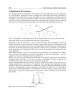
Recent advances in micro- and nanofabrication technologies have enabled the development
of miniaturized accelerometers, gyroscopes, μTAS chips, etc. These microdevices are made
of substrates having thicknesses relatively greater (~100μm) than the feature scale of the
microfabricated components (1~10 μm, Fig.1a). Conversely, the microscale organelles or
tissues of natural creatures are made of substrates, or membranes, that are relatively thin
compared to their feature size. For example, a human blood capillary, which is 10~100 μm
in diameter, has vessel walls with thicknesses of ~1 μm. To give another example, a cell with
a diameter of ~10 μm is composed of lipid bilayer membranes with thicknesses of ~10 nm.
This fundamental characteristic of the architecture of biological microstructures, which is
totally different from that of artificial microdevices, makes life a highly adaptable system
from both chemical and physical perspectives. The small thickness of the membrane
enhances transport of heat and substances between the body and its surroundings, and it
provides softness to the body, enabling passive and active morphological changes for
adapting to the environment. These characteristics of biological microstructures should
greatly encourage us to develop new types of MEMS and μTAS devices. However, in reality,
little research has been conducted on the development of 3-D microdevices composed of
thin membranes, which we call “3-D membrane microdevices” (Fig.1b).
Fig. 1. Schematics of (a) conventional “bulk“ microdevice and (b) “3-D membrane
microdevice“
Micro Electronic and Mechanical Systems
2
The purpose of this chapter is to introduce the concept of 3-D membrane microdevices and
highlight some advances being made in our laboratory. The chapter starts with a section
describing a novel microfabrication technique, namely, the membrane micro emboss
(MeME) process, which was developed to realize 3-D membrane microstructures. In the
following sections, several applications of 3-D membrane microdevices in μTAS and MEMS
fields are presented. First, a microfluidic device composed of thin porous biodegradable
membranes is described. This device was developed for tissue engineering purposes. Next,
a novel micropneumatic actuator composed of folded 3-D membrane chambers is described.
The actuator was intended for use as a microactive catheter for safer intravascular treatment.
Finally, we conclude the chapter and present our perspectives on 3-D membrane
microdevices.
2. Membrane Micro Emboss (MeME) process
Various micro fabrication processes can be used to fabricate MEMS or μTAS devices.
However, few processes are useful for the fabrication of 3-D membrane microstructure,
especially for polymer materials. Among conventional microfabrication processes, the
chemical vapor deposition (CVD) process using parylene and the microthermoforming
process can be employed. Although the CVD process using parylene is used to fabricate 3-
D membrane microstructures (Zhenga et al., 2007; Liua et al., 2008), the limitations caused
by the unavailability of suitable materials and low production rates present significant
problems. The microthermoforming process (Truckenmüller et al., 2002; Giselbrecht et al.,
2006) can be applied to a wide variety of thermoplastic materials and is suitable for mass
production; however, it cannot be applied to highly porous membranes because the
pressurized fluid leaks through the pores.
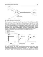
Fig. 2. Flowchart of the MeME process
Membrane Micro Emboss (MeME) Process for 3-D Membrane Microdevice
3
The MeME process (Fig.2) was developed to realize 3-D membrane microstructures from a
wide variety of materials including porous materials (Ikeuchi & Ikuta, 2005; Ikeuchi & Ikuta,
2006, a). This process needs a master mold, a thermoplastic polymer membrane, and a
deformable plastic support substrate. First, the polymer membrane is set between the master
mold and the support substrate. Then, this assemblage is heated to temperatures around the
glass transition point (Tg) of the polymer membrane. Next, the master mold is pressurized
against the membrane in vacuo. During pressurization, the membrane is deformed along
with the support substrate to match the surface of the master mold. After cooling to the
initial temperature, the master mold is separated from the deformed membrane. To fabricate
sealed microchannels, another planar membrane is placed on the deformed membrane and
sealed using heat-sealing, solvent gas bonding, or other sealing techniques. The fabrication
of the membrane microfluidic device is completed by dissolving the support substrate in a
selective solvent. The process is applicable to various materials, since it only requires the
membrane material to be thermoplastic. When polylactic acid (PLA) (Tg, 57
°
C; thickness, 5
μm) was used as a membrane material and paraffin (melting point, 70
°
C) was used as a
support substrate, the lateral and vertical resolutions of the process were at least 10 μm and
5 μm, respectively (Fig. 3) (Ikeuchi & Ikuta, 2006, a). The resolutions can be further
improved by using thinner membranes and harder support substrates.
In the following two sections, several applications of the MeME process are described.
Fig. 3. SEM images of the topside (upper) and backside (lower) of the deformed porous PLA
membrane.
3. Membrane microfluidic device for tissue engineering
3.1 Background
Throughout the history of biology, cell culture has been carried out on planar glass or in
polymer dishes. The cells cultured on a planar substrate proliferate laterally to form a thin
Micro Electronic and Mechanical Systems
4
layer of cells. Biologists have studied cellular dynamics using these two-dimensional cellular
constructs. In the natural environment, however, cells proliferate three-dimensionally, and
thus, show behaviours and functions different from those of cells in 2-D in vitro cultures.
Recently, cell culture in 3-D conditions has attracted considerable attention for studying
natural cell behaviours and, from a more practical perspective, for regenerating fully
functional large tissues and organs for transplantation. Some biologists culture cells under
3-D conditions by using soft hydrogel materials (collagen, Matrigel
TM
, etc.) or stacking cell
sheets (Liu & Bhatia, 2002; Bryant & Anseth, 2002; Sekiya et al., 2006.). There is a big
difference, however, between artificial 3-D conditions and in vivo conditions because of the
thickness of the cultured cellular constructs. Thick tissues in vivo can survive on nutrients
supplied from surrounding blood capillary networks. In contrast, we can stack only a few
layers of cells in vitro due to limitations with regard to the diffusion distance of nutrients,
which can be supplied only through the outer surface of the construct.
To solve this problem, King et al. (2004.) attempted to construct microfluidic chips made of
biodegradable polymers. They fabricated microchannels in biodegradable polymer
substrates using μTAS or lab-on-chip technologies, and they cultured cells on the chip by
supplying the culture medium through microchannels (Fig. 4a). They were unable to culture
thick tissues, however, because the cells cultured on the chip tended to be distributed at a
low density with poor homogeneity. These problems arise due to the thickness of the chip.
Cells seeded on the thick microchannel chips proliferate on the surface of the chip rather
than growing within the chip substrate.
In this section, we describe the MeME process as applied to fabricate 3-D thin membrane
microstructure, which solves the problems associated with conventional methods for tissue
engineering.
3.2 Artificial capillary network chip
To realize both the nutrients supply and homogeneous cell distribution in 3-D constructs,
we propose the artificial capillary network chip as a novel 3-D cell culture device (Fig. 4b).
This chip has a microchannel network made of a thin biocompatible polymer membrane
with penetrating micropores.
Cells seeded on this chip with soft hydrogel materials, or cells stacked on this chip as cell
sheets, can maintain a thick 3-D construct because of nutrients supplied from the porous
microchannel network. Unlike the thick conventional microchannel chip, the membrane
composing the microchannel wall is thin enough for cells to distribute homogeneously in
the 3-D constructs. Biodegradable polymers can be used, instead of conventional polymers,
as the membrane material to regenerate tissues for transplantation. Larger tissues can be
fabricated by stacking these chips (Fig. 4c).
A prototype of the chip with highly branched microchannels was fabricated from a porous
PLA membrane. The porous PLA membrane was formed by spin-coating following phase
separation technique (Ikeuchi & Ikuta, 2006, b). The diameter and density of the pores can
be controlled independently by adjusting the water content and PLA content of the coating
solution, respectively. Here, the pore diameter was adjusted to φ ~ 1 μm to prevent the cells
(φ ~ 5 μm) from entering the microchannel, and the thickness was adjusted to 5 μm.
The master mold was made by microstereolithography developed in our laboratory (Ikuta &
Hirowatari, 1993). The surface of the mold was coated with a fluorocarbon polymer for easy
Membrane Micro Emboss (MeME) Process for 3-D Membrane Microdevice
5
Fig. 4. (a) Schematic cross-section of the conventional microchannel chip for cell culture. (b)
Schematic cross-section of artificial capillary network chip. (c) Conceptual scheme of in vitro
3-D thick tissue regeneration using artificial capillary network chip
removal of the mold. The master mold was pressurized onto the membrane at 0.5 μm/s for
500 s. at 55°C in vacuo. After cooling to 25°C, the mold was removed. The embossed
membrane was heat-sealed with another membrane of the same material at 70°C for 30 s. A
red solution was filled into the microchannels by capillary force. No leaking or blockage of
the microchannel was observed (Fig. 5a). Figs. 5b and c show the topside and the backside of
a microchannel in the prototype chip before sealing, respectively. Most of the micropores
can be preserved on both sides of the microchannel wall even after the MeME process by
fine tuning the process parameters (speed, temperature, and material of support substrate).
3.3 Validation of the chip
To check the size-selective permeability of the microchannel wall of the chip, a suspension
of microbeads with diameters varying from φ100 nm to φ15 μm was poured on the chip (Fig.
6a). Beads smaller than φ1 μm penetrated the wall but larger beads were trapped on the
wall (Fig. 6b). This result means that nutrients and gases flowing through the microchannels
can diffuse out into the cellular constructs on the chip, while at the same time, the
microchannel walls support the thick 3-D cellular constructs.
The biocompatibility of the chip was also tested by culturing human endothelial cells
(HUVEC) using another prototype chip. Fig. 7a shows a fluorescent image of the cells on
the chip after culturing for 120 h. The cells spread as usual and showed no damage. The
time course of the cell density on the chip was also equivalent to that for conventional tissue
culture polystyrene flasks (Fig. 7b). These results prove that the chip was biocompatible
with HUVEC. The success of HUVEC culture on the microchannel offers interesting
possibilities for co-culture with other parenchyma cells to fabricate functional tissues.
Micro Electronic and Mechanical Systems
6
Fig. 5. A prototype chip made of a porous PLA membrane. (a) Optical microscopy image. (b,
c) SEM images of the topside and the backside of the chip, respectively.
Fig. 6. (a) Fluorescent microscopy image of the chip after pouring a microbead suspension
(b) Magnified view of the white-rectangle area in (a).
Membrane Micro Emboss (MeME) Process for 3-D Membrane Microdevice
7
Fig. 7. HUVEC culture on the chip. (a) Fluorescent view of the cell on the chip after 120 h. (b)
Transition of cell population density with culture time.
3.4 Summary
In this section, the artificial capillary network chip with a 3-D membrane microstructure was
proposed and its development from the viewpoint of realizing thick 3-D tissue culture in
vitro was described. Prototype chips were successfully fabricated using the MeME process,
and their size-selective permeability and biocompatibility were verified. This chip could
potentially become a key technology in the study of cellular dynamics under 3-D conditions;
moreover, it could be used to regenerate large tissues or organs for transplantation in the
near future.
4. Pressure-driven microactive catheter
4.1 Background
Recently, catheterization has been widely applied in intravascular surgery as an alternative
to conventional surgical techniques, which are highly invasive. In catheterization, a thin
flexible tube called a catheter is inserted into a blood vessel from the leg or arm. The catheter
can be advanced into the patient’s heart or brain for treatment or inspection. The operation
leaves just a tiny puncture on the arm or leg where the catheter has been inserted, and
therefore, causes less damage and fewer scars on the patient than conventional open
surgery.
A major problem with catheterization, however, is the difficulty of manipulation in narrow
and branched blood vessels. Since conventional catheters have no active bending capability
at the tip, the doctor can control the direction of the tip only by pushing and rotating the
catheter at the inlet which is far away from the tip. Thus, catheterization in narrow and
complicated blood vessels is extremely difficult.
To solve this problem, several types of active catheters have been proposed (Mineta et al.,
2002; Ikuta et al., 2003; Fang et al., 2007). They are classified into two types depending on the
bending mechanism. The first type consists of electrically driven active catheters. These
catheters have actuators that use shape memory alloys or polymer gels at the tip and can be
bent from outside the body by applying a current to the actuators. Even though electrical
actuators are suitable for miniaturization, the use of electricity inside the heart or brain
Micro Electronic and Mechanical Systems
8
poses the risk of fatal damage due to microshock or heat in the case of an accident (Manecke
et al., 2002; Bunch et al., 2005).
The second type consists of a pressure-driven active catheter, as proposed by Ikuta et al.
(2003). It has a hollow bellows made of soft silicone rubber at the tip, and the tip can be bent
by supplying saline water into the bellows through a tube connected to the bellows. Since no
electricity is necessary for actuation, it is superior in safety compared to electrically driven
active catheters. In addition, it can be applied to MRI monitoring, which is a fundamental
tool in catheterization, because no metal parts are used in this catheter. In spite of its
superiority, the minimum size of this type of catheter that can be attained with conventional
injection molding processes using a pair of a male and a female mold is φ ~ 1 mm, whereas
the catheter must be smaller than φ ~ 300 μm for complex intravascular surgery. This
limitation arises due to the difficulties involved in 3-D fabrication of a pair of male and
female molds with micrometer accuracy.
Although a pressure-driven balloon-type microactuator made from a polydimethylsiloxane
(PDMS) molding technique was reported for use in MEMS applications (Konishi et al.,
2006), it cannot be applied to catheterization due to the risk of damage to blood vessels
caused by large expansion of the actuator during bending. In short, there is no process
available to fabricate microscale pressure-driven active catheters.
In this section, we describe how the MeME process can be combined with an excimer laser
ablation technique to realize a pressure-driven microactive catheter with a 3-D thin
membrane microstructure.
4.2 Bellows composed of folded membrane microchambers
We designed a pressure-driven microactive catheter composed of hollow bellows; the
catheter was made of a biocompatible polymer membrane (thickness, 5 μm), a motorized
syringe, and a Teflon microtube (Fig. 8a). A pressure gauge was attached to the microtube at
the base to monitor the pressure and provide the pressure value as feedback to the
motorized syringe. The diameter of the catheter was set at φ 300 μm, because that is the
minimum size used in clinical practice.
The bellows are composed of a series of folded microchambers and microchannels
connecting the chambers. Since the bottom of each folded chamber is fixed to another
membrane, only the upper part of the chamber can be expanded by increasing the inner
pressure of the chamber (Fig. 8b). Thus, the bellows in their entirety can be bent in one
direction by supplying saline water from the syringe through the microtube, because only
one side of the bellows extends. Furthermore, the alternating arrangement of microchannels
and microchambers prevents the bellows from expanding in diameter during bending, since
the microchannels work as rigid frames to connect the topside and backside membranes of
the bellows.
The catheter was fabricated using the membrane micro emboss following excimer laser
ablation (MeME-X) process (Fig. 9) (Ikeuchi & Ikuta, 2008). In the MeME-X process, at first,
the hollow microbellows were formed from PLA membranes (thickness, 5 μm) using the
MeME process. By using excimer laser ablation (ArF, 193 nm), the outline of the bellows
was cut out from the sealed membranes, and an opening was made at one end. After the
bellows were connected to a microtube by an adhesive under an optical microscope, the
Membrane Micro Emboss (MeME) Process for 3-D Membrane Microdevice
9
Fig. 8. (a) Schematic of the pressure-driven microactive catheter system with bendable
bellows made of a thin membrane at the tip (b) Bending of the bellows through expansion of
each folded microchamber
Fig. 9. Flowchart of the MeME-X process
Micro Electronic and Mechanical Systems
10
support substrate was selectively dissolved by immersion in hexane. Finally, the catheter
was successfully fabricated (Fig. 10a). The entire process was completed in 10–15min. To
show the cross-section of the hollow bellows, the bellows were cut in the middle using the
excimer laser. The bellows composed of a series of folded microchambers and
microchannels were precisely fabricated on both the outside and the inside, and the thin
membrane was uniformly deformed to yield a hollow microstructure (Fig. 10b).
Fig. 10. (a) Completed pressure-driven micro active catheter φ 300 μm. (b) SEM image of the
bellows cut at the middle to show the cross-section and the inner structure.
4.3 Validation of the catheter
The bellows were bent at an arbitrary angle between 0° and 180° through water pressure
applied by a motorized syringe (Fig. 11a). The range of the bending angle is sufficient for
intravascular operation, and it can be extended by increasing the folding angle of each
microchamber of the bellows or by increasing the number of microchambers, if necessary.
Fig. 11. (a) Bending demonstration of the pressure-driven micro active catheter from 0 to 180
degrees. (b) Relation between applied pressure (P) and bending angle (θ) of the tip
(b)
(a)
(a)
(b)
Membrane Micro Emboss (MeME) Process for 3-D Membrane Microdevice
11
The hysteresis of the P-θ curve is apparently caused by the buckling behavior of the folded
chambers and air trapped in the microtube (Fig. 11b). The buckling behavior can be
improved by modifying the folding angle and pattern of the chambers, and the trapping of
air in the system can be prevented by assembling the catheter in vacuo. Most importantly,
little increase in the diameter of the bellows was observed during bending due to the
microchannels inserted between the microchambers. This leads to a safer and smoother
insertion of the catheter at bifurcations.
For in vitro demonstration of the active catheter, a small blood vessel model made of silicone
was fabricated using the lost-wax method. The model consists of narrow blood vessels of φ 1
~ 3 mm into which conventional active catheters could not be inserted. The pressure-driven
microactive catheter was actuated and inserted into the narrow vessels (Fig. 12a). At the
bifurcation, the catheter was bent slightly to the left from the straight position (Fig. 12b,c) by
supplying saline water from the syringe, turned to the desired direction, and then
successfully introduced into the target aneurysm (Fig.12d).
Fig. 12. Video frames showing insertion of the catheter into a 3-D vascular model
4.4 Summary
In this section, the pressure-driven microactive catheter was proposed and its development
by the MeME-X process was described. The pressure-driven microactive catheter, with its
extremely small size and high safety, should promote the application of catheterization in
tip of the catheter
vessel wall
(a) (b)
(c) (d)
tar
g
et aneur
y
sm
Micro Electronic and Mechanical Systems
12
complex intravascular surgery, which is at present not possible with conventional surgical
tools. For further improvements, microchannels for drug delivery and/or blood sampling
could be attached to the bellows. This can be achieved by simply adding microchannel
templates on the master mold of the bellows. Furthermore, the nonelectrical actuation
mechanism of this catheter, which has a 3-D membrane microstructure, can be widely
extended to safe medical tools and microactuators in the microrobotics field.
5. Conclusions and perspectives
In this chapter, the concept of 3-D membrane microdevices was introduced and the
development of the MeME process was described. To utilize its characteristics, the concept
was applied to actual devices in two different fields. First, focusing on the efficient transfer
of substances and heat in 3-D membrane microchannels, an artificial capillary network chip
was developed for tissue engineering purposes. Second, utilizing the high elastic
deformability of 3-D membrane microstructures, hollow bellows composed of folded
microchambers and microchannels were developed to realize a pressure-driven microactive
catheter.
Biological organisms are fundamentally characterized by a 3-D membrane microstructure.
From intracellular organelles to vascular networks, from plant leaves to insect wings, the
exquisite architectures prevalent in nature greatly inspires us to develop novel
micro/nanodevices. The study of 3-D membrane microdevices has just emerged out of the
proof-of-concept stage. To further expand the scope of applications of 3-D membrane
microdevices, our laboratory is actively engaged in the exploration of a variety of materials
applicable to the MeME process and improvement of the resolutions of the MeME process
toward the nanometer scale. With its unique advantages, the 3-D membrane microdevice
technology should contribute to drug delivery, tissue engineering, electric power
generation, smart skin development and many other fields in the near future.
6. References
Bryant, S. & Anseth, K. (2002). Hydrogel properties influence ECM production by
chondrocytes photoencapsulated in poly(ethylene glycol) hydrogels. Journal of
Biomedical Materials Research, Vol. 59, Issue 1, 63-72.
Bunch, T.J., Bruce, G.K., Mahapatra S., Johnson S.B., Miller D.V., Sarabanda A.V., Milton
M.A. & Packer D.L. (2005). Mechanisms of phrenic nerve injury during
radiofrequency ablation at the pulmonary vein orifice. Journal of Cardiovascular
Electrophysiology, Vol. 16, Issue 12, 1318-1325.
Fang, B.K., Ju, M.S. & Lin, C.C.K. (2007). A new approach to develop ionic polymer–metal
composites (IPMC) actuator: Fabrication and control for active catheter systems.
Sensors and Actuators A, Vol. 137, Issue 2, 321-329
Giselbrecht, S., Gietzelt, T., Gottwald, E., Trautmann, C., Truckenmüller, R., Weibezahn,
K.F. & Welle, A. (2006). 3D tissue culture substrates produced by
microthermoforming of pre-processed polymer films. Biomedical Microdevices, Vol.
8, Issue 3, 191-199.
Membrane Micro Emboss (MeME) Process for 3-D Membrane Microdevice
13
Ikeuchi, M. & Ikuta, K. (2005), Fabrication of biodegradable membrane micro-channels for
artificial blood capillary networks using membrane micro embossing (MeME).
Transactions of JSMBE. Vol. 43, Issue 4, 646-652
Ikeuchi, M. & Ikuta, K. (2006,a). The membrane micro emboss (MeME) process for
fabricating 3-D microfluidic device formed from thin polymer membrane. Proc.
μ
TAS’06, pp. 693-695, ISBN4-9903269-0-3-C3043, Tokyo, Nov. 2006.
Ikeuchi, M. & Ikuta, K. (2006,b). On-site size-selective particle sampling using mesoporous
polymer membrane microfluidic device. Proc.
μ
TAS’06, pp. 1169-1171, ISBN4-
9903269-0-3-C3043, Tokyo, Nov. 2006.
Ikeuchi, M. & Ikuta, K. (2008). Membrane micro emboss following excimer laser ablation
(MeME-X) process for pressure-driven micro active catheter. Proc. MEMS’08, pp.
62-65, ISBN978-1-4244-1792-6, Tucson, Jan. 2008.
Ikuta, K. & Hirowatari, K. (1993). Real three dimensional micro fabrication using stereo
lithography and metal molding. Proc. MEMS’93, pp. 42-47, ISBN0-7803-0957-X, Fort
Lauderdale, Feb. 1993.
Ikuta, K., Ichikawa, H., Suzuki, K. & Yamamoto, T. (2003). Safety active catheter with multi-
segments driven by innovative hydro-pressure micro actuators. Proc. MEMS’03, pp.
130-135, ISBN0-7803-7744-3, Kyoto, Jan. 2003.
King, K., Wang, C., Mofrad, M., Vacanti, J.P. & Borenstein, J. (2004). Biodegradable
microfluidics. Advanced Materials, Vol. 16, 2007-2012
Konishi, S., Nokata, M., Jeong, O.C., Kusuda, S., Sakakibara, T., Kuwayama, M. & Tsutsumi,
H. Pneumatic micro hand and miniaturized parallel link robot for micro
manipulation robot system, Proc. ICRA’06, pp. 1036-1041, ISBN0-7803-9505-0,
Orlando, May 2006.
Liu, V. & Bhatia, S. (2002). Three-dimensional photopatterning of hydrogels containing
living cells. Biomedical Microdevices, Vol. 4, Issue 4, 257-266.
Liua, M.C., Hob, D. & Tai, Y.C. (2008). Monolithic fabrication of three-dimensional
microfluidic networks for constructing cell culture array with an
”integrated combinatorial mixer. Sensors and Actuators B, Vol. 129, Issue 2,
826-833
Manecke, G.R., Brown, J.C. Landau, A.A., Kapelanski, D.P., St. Laurent, C.M. & Auger,
W.R. (2002). An unusual case of pulmonary artery catheter malfunction. Anesthesia
Analgesia, Vol. 95, 302-304.
Mineta, T., Mitsui, T., Watanabe, Y., Kobayashi, S., Haga, Y. & Esashi, M. (2002). An active
guide wire with shape memory alloy bending actuator fabricated by room
temperature process. Sensors and Actuators A, Vol. 97-98, 632-637
Sekiya, S., Shimizu, T., Yamato, M., Kikuchi, A. & Okano, T. (2006). Bioengineered cardiac
cell sheet grafts have intrinsic angiogenic potential. Biochemical and Biophysical
Research Communications, Vol. 341, Issue 2, 573-82.
Truckenmuller, R., Rummler, Z., Schaller, T. & Schomburg, W.K. (2002). Low-cost
thermoforming of micro fluidic analysis chips. Journal of Micromechanics and
Microengineering, Vol. 12, 375–379
Micro Electronic and Mechanical Systems
14
Zhenga, J., Webstera, J.R., Mastrangelob, C.H., Ugazc, V.M., Burnsd M.A. & Burkee, D.T.
(2007). Integrated plastic microfluidic device for ssDNA separation. Sensors and
Actuators B, Vol. 125, Issue 1, 343-351
2
A Review of Thermoelectric MEMS Devices
for Micro-power Generation, Heating
and Cooling Applications
Chris Gould and Noel Shammas
Staffordshire University
UK
1. Introduction
Thermoelectric technology can be used to generate a small amount of electrical power,
typically in the µW or mW range, if a temperature difference is maintained between two
terminals of a thermoelectric module. Alternatively, a thermoelectric module can operate as
a heat pump, providing heating or cooling of an object connected to one side of a
thermoelectric module if a DC current is applied to the module’s input terminals. This
chapter reviews the development of microelectromechanical systems (MEMS) based
thermoelectric devices suitable for micro-power generation, heating and cooling
applications. The chapter begins with a brief overview of thermoelectric technology, macro-
thermoelectric module construction and operation. Micro-thermoelectric modules are
introduced, and a review of recent developments in research, commercial development, and
typical application of MEMS based micro-thermoelectric devices is made. The chapter
draws conclusions on the development and potential application of MEMS based
thermoelectric devices suitable for thermoelectric cooling, heating and micro-power
generation.
2. Overview of thermoelectric technology, module construction and
operation
2.1 Overview of thermoelectric technology
Thermoelectricity utilises the Seebeck, Peltier and Thomson effects that were first observed
between 1821 and 1851 (Nolas et al, 2001). Practical thermoelectric devices emerged in the
1960’s and have developed significantly since then with a number of manufacturers now
marketing thermoelectric modules for cooling, heating and power generation applications.
Thermoelectric power generation is mainly influenced by the Seebeck effect, with
thermoelectric cooling and heating influenced predominantly by the Peltier effect. The
Thomson effect does not have a major influence although it should always be included in
detailed calculations (Rowe, 2006). For power generation applications, a small amount of
electrical power, typically in the µW or mW range, can be generated by a thermoelectric
module if a temperature difference is maintained between two terminals of a thermoelectric
module. Alternatively, a thermoelectric module can operate as a heat pump, providing